US4786900A - Electronic key apparatus - Google Patents
Electronic key apparatus Download PDFInfo
- Publication number
- US4786900A US4786900A US06/910,649 US91064986A US4786900A US 4786900 A US4786900 A US 4786900A US 91064986 A US91064986 A US 91064986A US 4786900 A US4786900 A US 4786900A
- Authority
- US
- United States
- Prior art keywords
- encrypted code
- data
- electronic lock
- encrypted
- coincidence
- Prior art date
- Legal status (The legal status is an assumption and is not a legal conclusion. Google has not performed a legal analysis and makes no representation as to the accuracy of the status listed.)
- Expired - Lifetime
Links
Images


Classifications
-
- G—PHYSICS
- G07—CHECKING-DEVICES
- G07C—TIME OR ATTENDANCE REGISTERS; REGISTERING OR INDICATING THE WORKING OF MACHINES; GENERATING RANDOM NUMBERS; VOTING OR LOTTERY APPARATUS; ARRANGEMENTS, SYSTEMS OR APPARATUS FOR CHECKING NOT PROVIDED FOR ELSEWHERE
- G07C9/00—Individual registration on entry or exit
- G07C9/00174—Electronically operated locks; Circuits therefor; Nonmechanical keys therefor, e.g. passive or active electrical keys or other data carriers without mechanical keys
- G07C9/00182—Electronically operated locks; Circuits therefor; Nonmechanical keys therefor, e.g. passive or active electrical keys or other data carriers without mechanical keys operated with unidirectional data transmission between data carrier and locks
-
- G—PHYSICS
- G07—CHECKING-DEVICES
- G07C—TIME OR ATTENDANCE REGISTERS; REGISTERING OR INDICATING THE WORKING OF MACHINES; GENERATING RANDOM NUMBERS; VOTING OR LOTTERY APPARATUS; ARRANGEMENTS, SYSTEMS OR APPARATUS FOR CHECKING NOT PROVIDED FOR ELSEWHERE
- G07C9/00—Individual registration on entry or exit
- G07C9/20—Individual registration on entry or exit involving the use of a pass
- G07C9/22—Individual registration on entry or exit involving the use of a pass in combination with an identity check of the pass holder
-
- G—PHYSICS
- G07—CHECKING-DEVICES
- G07C—TIME OR ATTENDANCE REGISTERS; REGISTERING OR INDICATING THE WORKING OF MACHINES; GENERATING RANDOM NUMBERS; VOTING OR LOTTERY APPARATUS; ARRANGEMENTS, SYSTEMS OR APPARATUS FOR CHECKING NOT PROVIDED FOR ELSEWHERE
- G07C9/00—Individual registration on entry or exit
- G07C9/00174—Electronically operated locks; Circuits therefor; Nonmechanical keys therefor, e.g. passive or active electrical keys or other data carriers without mechanical keys
- G07C2009/00753—Electronically operated locks; Circuits therefor; Nonmechanical keys therefor, e.g. passive or active electrical keys or other data carriers without mechanical keys operated by active electrical keys
- G07C2009/00769—Electronically operated locks; Circuits therefor; Nonmechanical keys therefor, e.g. passive or active electrical keys or other data carriers without mechanical keys operated by active electrical keys with data transmission performed by wireless means
- G07C2009/00785—Electronically operated locks; Circuits therefor; Nonmechanical keys therefor, e.g. passive or active electrical keys or other data carriers without mechanical keys operated by active electrical keys with data transmission performed by wireless means by light
-
- G—PHYSICS
- G07—CHECKING-DEVICES
- G07C—TIME OR ATTENDANCE REGISTERS; REGISTERING OR INDICATING THE WORKING OF MACHINES; GENERATING RANDOM NUMBERS; VOTING OR LOTTERY APPARATUS; ARRANGEMENTS, SYSTEMS OR APPARATUS FOR CHECKING NOT PROVIDED FOR ELSEWHERE
- G07C2209/00—Indexing scheme relating to groups G07C9/00 - G07C9/38
- G07C2209/60—Indexing scheme relating to groups G07C9/00174 - G07C9/00944
- G07C2209/62—Comprising means for indicating the status of the lock
Definitions
- the present invention relates to an electronic key apparatus which comprises a memory for storing an encrypted or secret code for releasing a lock, and which supplies an encrypted code stored in the memory, by means of radio wave, light, ultrasonic wave, or the like, to release a lock.
- a conventional security apparatus for a gate or door of a house or room, a door of a vehicle, a door or lid of a safe, desk, locker, drawer, or the like comprises a lock mechanism consisting of a mechanical lock and a key.
- the lock mechanism can be released only when a combination of mechanical factors, such as a three-dimensional shape in the lock, or the length or position or presence/absence of a pin or cylinder, coincides mechanically or dynamically with the three-dimensional shape, length, or position of the key or the presence/absence thereof.
- an electronically controlled lock apparatus has been developed in place of the mechanical lock mechanism using the mechanical lock and the key.
- the lock has a plurality of numerical buttons, and electronic information "1" or "0" is input, by means of an electric signal (e.g., a high or low voltage level, or a large or small current, or an ON/OFF pulse) upon depression of buttons corresponding to a predetermined number, thereby locking/unlocking the lock mechanism, without using a mechanical key.
- an apparatus which can lock/unlock the lock mechanism from a distant location, by remote control, using a radio wave, or an apparatus utilizing a magnetic strip card on which an encrypted code is recorded on magnetic tape, is known.
- U.S. Pat. No. 4,573,046 describes an electronic locking system which comprises a wristwatch which has a memory for storing a code for releasing a lock, and which radiates the code to the lock by way of an optical means, and also describes an apparatus for releasing the lock, in response to a predetermined code.
- the number to be input, in respect of each lock must be memorized. If there are a plurality of locks, the user may easily forget their numbers.
- a remote control unit In the apparatus utilizing remote control, a remote control unit must be prepared for each lock, and the user must bring them with him. There is always the risk that the user may lose one or more the remote control units.
- the user In the apparatus using the magnetic strip card, the user must carry around a large number of cards corresponding to the respective locks, and he may easily lose these cards.
- the present invention has been made in consideration of the above situation, and has as its object to provide an electronic key apparatus which can be commonly used for a large number of locks, and which has excellent security and crime-prevention functions.
- encrypted-code storage means for storing an encrypted code for unlocking an electronic lock
- pass data storage means for storing password data
- data-coincidence detection means for detecting a coincidence between the data input by said data-input switch means and the pass data stored in said pass data storage means
- encrypted-code transmitting means for transmitting the encrypted code stored in said encrypted-code storage means to said electronic lock, when a coincidence is detected by said data-coincidence detection means.
- an electronic key apparatus can set, update, and output an encrypted code only when the input pass data coincides with prestored data. Therefore, a lock can be protected from being unlocked by a third party, or an encrypted code can be prevented from being updated without permission, thus providing the electronic key apparatus with high security.
- FIG. 1 is a perspective view of an electronic wristwatch according to an embodiment of the present invention
- FIG. 2 is a perspective view of a jewel box, the lock mechanism of which is released by the wristwatch shown in FIG. 1;
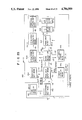
- FIG. 3 is a circuit diagram showing the circuit arrangement of the wristwatch, and the jewel box shown in FIGS. 1 and 2;
- FIG. 4 is an internal memory map of a RAM shown in FIG. 3;
- FIG. 5 is a general flow chart showing the functions of the wristwatch shown in FIG. 1;
- FIG. 6 is a flow chart showing the processing when switch S1 is depressed in key-processing a3 shown in FIG. 5;
- FIG. 7 is a diagram showing a change of display mode upon depression of keys
- FIG. 8 is a flow chart showing the processing when switch S2 is depressed
- FIG. 9 is a flow chart showing the processing when switch S3 is depressed.
- FIG. 10 is a flow chart showing the processing when switch S4 is depressed
- FIG. 11 is a flow chart showing the processing when switch S5 is depressed
- FIG. 12 is a flow chart showing the processing when switch S6 is depressed
- FIG. 13 is a detailed flow chart of timepiece processing in step a2 in FIG. 5;
- FIG. 14 is a detailed flow chart of timepiece processing h1 in FIG. 13;
- FIGS. 15A and 15B are detailed flow charts of mode-detection processing h2 and display processing h3 shown in FIG. 13;
- FIGS. 16A through 16F are representations showing display states of a display section in the respective modes
- FIG. 17 is a perspective view of an electronic wristwatch according to another embodiment of the present invention.
- FIG. 18 is a perspective view of a jewel box according to this other embodiment of the present invention.
- FIG. 19 is a circuit diagram of the wristwatch shown in FIG. 17;
- FIG. 20 is a circuit diagram of the jewel box shown in FIG. 18;
- FIG. 21 is an internal memory map of RAM 23 shown in FIG. 19;
- FIGS. 22A through 22C are flow charts showing the operation of the wristwatch shown in FIG. 17;
- FIG. 23 is a diagram showing a change of display mode upon depression of keys of the wristwatch shown in FIG. 17;
- FIGS. 24A through 24I are representations showing display states of a display section, in the respective modes
- FIG. 25 is a circuit diagram showing another embodiment of the present invention.
- FIG. 26 is a circuit diagram showing still another embodiment of the present invention.
- FIGS. 27A-27B are circuit diagrams showing still another embodiment of the present invention.
- FIGS. 28A-28B are detailed circuit diagrams of the circuit configuration shown in FIG. 27;
- FIG. 29 is a perspective view showing still another embodiment of the present invention.
- FIG. 30 is a perspective view showing still another embodiment of the present invention.
- FIGS. 31A-31B are circuit diagrams of the embodiment shown in FIG. 29.
- FIG. 1 is a perspective view showing an embodiment in which the present invention is applied to an electronic wristwatch.
- wristwatch casing 1 has a display section 2 comprising, for example, a liquid crystal display device, and key-operation section 3 comprising various keys 3a.
- Switches S1, S2, and S3, and LED 4 are arranged on the side end face of display section 2.
- FIG. 2 is a perspective view of jewel box 10, the lock mechanism of which is released by a signal emitted from the wristwatch shown in FIG. 1.
- Jewel box 10 comprises a casing 11 and lid 12.
- Lid 12 is mounted on casing 11, to be openable/closable by means of a hinge (not shown), as indicated by numeral 12a in FIG. 2.
- Projection 13 engaged with an engaging portion arranged inside casing 11 is formed on the inner surface of lid 12.
- Projection 13 and the engaging member constitute a lock mechanism. When lid 12 is closed, projection 13 and the engaging member are engaged with each other, to automatically lock the lock mechanism.
- Switches 14 are rotated to obtain a desired combination of numerals, and are electrically connected to the lock mechanism.
- the lock mechanism is released when a light signal corresponding to a number (e.g., "0425,” in FIG. 2) set by switches 14 is output from LED 4 of the wristwatch shown in FIG. 1, and is received through key hole 15, or the lock mechanism is released by a predetermined key.
- FIG. 3 shows the circuit configuration of wristwatch casing 1 and jewel box 10 shown in FIGS. 1 and 2, respectively.
- ROM 21 is a fixed memory, which prestores a program or data for controlling the entire system.
- Address controller 22 is an address section of ROM 21 for defining the program flow, and receives the output signals of ROM 21, operation section 25 (or ALU), and frequency-divider 27.
- RAM 23 is a memory which outputs data stored at an address specified by address signal 21a from ROM 21 to operation section 25 or converter 29, and receives the result processed by section 25, to store it therein.
- Instruction decoder 24 decodes instruction output signal 21b of ROM 21, and sends a control signal to respective blocks.
- Operation section 25 performs an arithmetic operation using data in RAM 23, based on an instruction from ROM 21 and key-input section 28.
- Section 25 writes the result at an address in RAM 23 specified by ROM 21, and displays it in display section 2.
- Display section 2 is the same as that shown in FIG. 1.
- Signal 21c output from ROM 21 is a next address signal for specifying the next address.
- Oscillator 26 generates a clock signal having a given period.
- Timing generator 27 frequency-divides the clock signal to a predetermined frequency, and generates a timing signal for time-serially controlling the respective function blocks.
- Key-input section 28 is a block for instructing various processing operations, to the corresponding function blocks, in response to key operations, and includes switches S1, S2, and S3, and key-operation section 3, shown in FIG. 1.
- Converter 29 converts an encrypted code (to be described later), written in RAM 23, into H (High)-level and L (Low)-level electrical signals.
- Transistor 30 is turned on or off in accordance with the output signal of converter 29, and LED 4 is turned on or off in response to this, thereby generating a light signal indicating the encrypted code.
- LED 4 is the same as that shown in FIG. 1.
- Photodiode 31 is turned on or off upon reception of the light signal from LED 4, to convert the light signal into an electrical signal. Note that photodiode 31 is arranged in key hole 15, to be able to detect light propagating from an external circuit through hole 15. A phototransistor can be used in place of photodiode 31.
- Amplifier 32 amplifies the electrical signal obtained by photodiode 31, and low-pass filter 33 derives a low-frequency component from the output signal of amplifier 32.
- Converter 34 converts the output signal of low-pass filter 33 into a digital signal (encrypted code).
- Coincidence detector 35 compares the number set by switches 14 and the digital signal (encrypted code) output from converter 34.
- Lock mechanism 36 is constituted by projection 13 and the engagement member of casing 11, shown in FIG. 2. Upon reception of the coincidence signal, engagement between projection 13 and the engagement member is released, thereby releasing a lock.
- FIG. 4 shows the internal memory map of RAM 23 described above.
- RAM 23 comprises time register W, display register X, item storage register Y, encrypted-code storage register Z, password data (i.e., pass data) storage register H, password data-set flag L, electronic key-operation mode flag M, password data-input mode flag N, mode-selection flag O, password data-update mode flag P, item/code-update/set flag Q, item-input mode flag R, code-output mode flag S, timer T, and the like.
- password data i.e., pass data
- Time register W is a register for storing time data, for example, hours, minutes, seconds, 1/16 seconds, and the like
- display register X is a register for temporarily storing data displayed in display section 2.
- Item storage register Y and encrypted-code storage register Z comprise a plurality of registers, and the respective registers store items corresponding to various locks and the encrypted code set for each item. For example, in FIG. 4, an item for jewel box 10 is set to be "JEWEL", and the encrypted code corresponding thereto is set to be "0425”. Items for doors of a house, a vehicle, and an office are set to be "DOOR”, “CAR”, and "OFFICE”, respectively, and the encrypted codes are set in correspondence therewith.
- Password data storage register H stores password data, i.e., data comprising a secret number or symbol which is known to a specific person. In FIG. 4, register H stores password data "0011".
- Password data-set flag L is set to be “1" when password data is set in register H.
- Electronic key-operation mode flag M is set to be “1” when a display mode associated with the operation of an electronic key other than a time display mode (electronic key-operation mode; to be described later) is selected.
- Password data-input mode flag N, mode-selection flag O, password data-update mode flag P, item/code-update/set flag Q, item-input mode flag R, and code-output mode flag S are set to be “1” respectively, when password data-input mode, a mode-selection mode, a password data-update mode, an item/code-update/set mode, an item-input mode, and a code-output mode.
- Timer T measures time in units of seconds, and the measurement result serves as a timing signal for automatically switching the predetermined display modes.
- FIG. 5 is a general flow chart. If there is no key-processing instruction in the HALT state (a1), timepiece processing is executed every 1/16 sec (a2). The timepiece processing is executed in response to a timepiece clock signal output from timing generator 27, shown in FIG. 3 (to be described later in detail), every 1/16 sec. Time data obtained by this processing is stored in time register W, in RAM 23, shown in FIG. 4.
- keyboard processing is executed (a3).
- the key processing is executed by ROM 21, RAM 23, and the like, based on the signal output from key-input section 28, shown in FIG. 3, upon operation of the keys.
- FIG. 6 is a flow chart showing the processing when switch S1 is depressed, and FIG. 7 shows a change of display state, upon depression of the keys.
- switch S1 When switch S1 is depressed, it is checked, in step b1, if electronic key-operation mode flag M is "1", as shown in FIG. 6.
- flag M When flag M is "0", a time-display mode is set, and when flag M is "1", the display mode for the electronic keys is set, as shown in FIG. 7.
- M 1 i.e., if a time-display mode (i.e., mode m1 in FIG. 7) is selected, flag M is set to be "1" and timer T is reset, in step b2.
- the display mode is electronic key mode (mode m2 in FIG. 7).
- FIG. 8 shows processing upon operation of switch S2.
- FIG. 9 shows processing upon operation of switch S3.
- FIG. 10 shows processing upon operation of switch S4.
- An encrypted code corresponding to an input item is derived from register Z, in FIG. 4, in step e4, and is sent to converter 29, shown in FIG. 3.
- FIG. 11 shows processing upon operation of switch S5.
- Timepiece processing a2 executed every 1/16 sec, shown in FIG. 5, comprising timepiece-processing step h1, mode-detection processing step h2, and display-processing step h3, as shown in FIG. 13.
- FIG. 14 shows step h1 in detail.
- step i1 the presence/absence of a 1/16-sec timepiece clock signal is checked. If the signal is detected, a 1/16-sec counter (not shown) in time register W in RAM 23, shown in FIG. 4, is incremented by 1, in step i2. It is checked, in step i3, if the 1/16-sec counter has counted 16, i.e., if one second has passed. If one second has passed, the 1/16-sec counter is reset and a second counter (not shown) in register W is incremented by 1, in step i4. It is checked, in step i5, if the second counter has counted 10, i.e., if 10 seconds have passed.
- step i6 If 10 seconds have passed, the second counter is reset and a 10-sec counter (not shown) in register W is incremented by 1, in step i6. It is checked, in step i7, if the 10-sec counter has counted 6, i.e., one minute has passed. If one minute has passed, the 10-sec counter is reset and a minute counter (not shown) in register W is incremented by one, in step i8. In this manner, other timepiece processing in unit times is similarly executed, in step i9.
- FIGS. 15A and 15B show steps h2 and h3 shown in detail, in FIG. 13.
- step j1 it is checked, in step j1, if flag M is "1". If M ⁇ 1, time data is displayed, in step j2. This time display is performed such that time data written in register W by timepiece processing, shown in FIG. 14, is temporarily written in register X and is then displayed in display section 2.
- FIG. 16A shows this display state.
- FIG. 16D shows this display state.
- step j6 If a noncoincidence is found in step j6, error processing is executed, in step j9, and the display mode is switched to error-display mode m5, in step j10, thus performing error display. If L ⁇ 1, in step j4, flag N is set to be "0", in step j11, and the display mode is switched to password data-set mode m4, in step j12, thus performing password data-set display.
- step k7 i.e., if the display mode has just been switched from time-display mode m1 to electronic key mode m2
- timer processing is performed by timer T, shown in FIG. 4 in step k12, and it is checked, in step k13, if two seconds have passed. If two seconds have not yet passed, electronic key mode display, shown in FIG. 16B is performed, in step k14. If two seconds have passed, timer T is reset and flag N is set to be "1", in step k15. Then, input password data is displayed, in step k16.
- FIG. 16C illustrates this display state. In FIG. 16C, password data "0011" is input.
- time data is displayed as shown in FIG. 16A.
- switch S1 is depressed in this state.
- the display mode is switched to electronic key mode m2, and the electronic key is displayed, as shown in FIG. 16B.
- the display mode is switched to password data-input mode m3. If password data, for example, "0011", is input in this state, input password data is displayed as shown in FIG. 16C. Only when the input password data coincides with preset password data, is the display mode switched to mode-selection mode m6, and the electronic key can then be used. If a noncoincidence is found, the display mode is switched to error-display mode m5, and error display (not shown) is performed. Thereafter, when one second has passed, the display mode is again switched to password data-input mode m3. If errors are detected on three successive occasions, the display mode returns to time-display mode m1.
- password data for example, "0011"
- the display shown in FIG. 16D is performed. If the electronic lock is to be released, in this case, switch S5 is depressed. Then, the display mode is switched to item-input mode m7. In this state, when an item corresponding to a desired electronic lock, for example, "JEWEL" for a jewel box, is input, the input item is displayed as shown in FIG. 16E. When an encrypted code corresponding to the displayed item is to be output, the light-output direction of LED 4, shown in FIG. 1, is directed toward key hole 15, in FIG. 2, and only switch S4 need be depressed.
- a desired electronic lock for example, "JEWEL" for a jewel box
- the display mode While the encrypted code is output, the display mode is switched to code-output mode m8, and the flickering display shown in FIG. 16F is performed. After output of the encrypted code is completed, the display mode is again switched to item-input mode m7. In this manner, when the encrypted code is to be output to the electronic lock, it need not be input, and only an item corresponding to a desired electronic lock need be input.
- switch S1 When an item and an encrypted code are to be updated or set, switch S1 is depressed, in mode-selection mode m6. Thus, the display mode is switched to item/code-update/set mode m10, and the item and the encrypted code can be updated or set in this state. Each time switch S6 is depressed, the item and the encrypted code are sequentially switched. When switch S1 is depressed again, the display mode returns to mode-selection mode m6.
- switch S2 When password data is to be updated, switch S2 is operated, in mode-selection mode m6. Then, the display mode is switched to password data-update mode m9, and password data can be updated in this state. If the display mode is to be returned to mode-selection mode m6, only switch S2 need be depressed.
- the present invention is not limited to the wristwatch described above, but can be applied to a pocket-type compact calculator or to other equipment worn or carried by the user.
- the jewel box has been exemplified as the electronic lock apparatus.
- the present invention is not limited to this.
- the present invention can be applied to an electronic lock incorporated in the doors of a house, an office, a vehicle, and the like.
- RAM 23 can be a nonvolatile memory, more specifically, an EEPROM. With this arrangement, even if a dry cell of a wristwatch or the like is used up, the encrypted codes will not be erased.
- the medium for transmitting an encrypted code is not limited to light from an LED, but can be a radio wave, a sound wave, and the like.
- An item i.e., item data
- An item can be the full name of an object, or it can be an initial character thereof or two to three characters from the initial character.
- items can be sequentially designated by a single switch.
- Password data is not limited to the number described above, but can be the number of operation times of a predetermined switch or an operation time interval, or a combination of various operation switches, or specific voice data or speech data, when a voice recognition function is provided.
- FIGS. 17 through 24I show another embodiment of the present invention.
- FIG. 17 shows an electronic wristwatch, in which switches S1 through S3 are arranged at one side of display section 2, LED 4a and photodiode 5a are arranged at the other side of section 2, and other arrangements are the same as those shown in FIG. 1.
- FIG. 18 shows substantially the same jewel box as that shown in FIG. 2.
- the difference between the jewel boxes shown in FIGS. 2 and 18 is that photodiode 6a and LED 7a are arranged at a distance equal to that between LED 4a and photodiode 5a of the wristwatch shown in FIG. 17.
- FIG. 19 shows the circuit configuration of wristwatch casing 1 shown in FIG. 17.
- the same reference numerals in FIG. 19 denote the same parts as in FIG. 3, and a detailed description thereof will be omitted.
- receiver 5 is added to the circuit shown in FIG. 19.
- Receiver 5 comprises photodiode 5a, shown in FIG. 17, amplifier 5b, low-pass filter 5c, and the like, and receives a response signal (to be described later) emitted from LED 7a of jewel box 10, to convert it into an electrical signal, thereby outputting the converted electrical signal.
- FIG. 20 shows the circuit configuration of jewel box 10.
- Reference numeral 16 denotes a receiver.
- Receiver 16 comprises photodiode 6a, shown in FIG. 18, amplifier 6b, low-pass filter 6c, and the like, and receives a light signal from LED 4a, to convert it into an electrical signal.
- Reference numeral 41 denotes a converter.
- Converter 41 converts an output signal from receiver 16 into a parallel digital signal (encrypted code).
- Coincidence detector 42 compares an encrypted code set by digital switches 14, and an encrypted code output from converter 41. When detector 42 detects a coincidence therebetween, it generates a coincidence signal; otherwise, it generates a noncoincidence signal.
- Lock mechanism 43 comprises projection 13 and an engagement portion of casing 11, shown in FIG. 18. When mechanism 43 receives the coincidence signal, projection 13 and the engagement portion are disengaged, and the lock is released.
- the coincidence or noncoincidence signal is delayed by delay circuit 44, and is then sent to converter 45.
- Converter 45 converts the coincidence or noncoincidence signal into a serial ON or OFF signal, and sends it to transmitter 47.
- Transmitter 47 comprises LED 7a, shown in FIG. 18, and transistor 47b, and converts the output signal from converter 45 as a response signal, into a light signal and then outputs it.
- the response signal is received by receiver 5 of the wristwatch, as is described above.
- FIG. 21 shows a memory map of RAM 23, shown in FIG. 19.
- RAM 23 comprises time register W, display register X, item storage register Y, encrypted-code storage register Z, password data storage register H, password data-set flag L, electronic key-operation mode flag M, password data-input mode flag N, mode-selection flag O, password data-update mode flag P, item/code-update/set flag Q, item-input mode flag R, code-output mode flag S, status-display mode flag V, timers T and U, and the like.
- Time register W stores time data, i.e., hour, minute, second, and 1/16 sec data
- display register X temporarily stores data displayed in display section 2.
- Item storage register Y and encrypted-code storage register Z each comprise a plurality of registers, which store items corresponding to various electronic locks or encrypted codes set for each item.
- an item corresponding to jewel box 10 is set to be "JEWEL”, and an encrypted code corresponding thereto is set to be, for example, "0425”.
- Items for doors of a house, a vehicle, and an office are set to be "DOOR”, "CAR”, and "OFFICE”, and encrypted codes therefor are set in correspondence therewith.
- Password data storage register H stores password data, i.e., data including a secret number or symbol which is known to a specific person, and stores, for example, password data "0011".
- Password data-set flag L is set to be “1” when password data is set in register H.
- Electronic key-operation mode flag M is set to be “1” when a display mode associated with the operation of the electronic key (an electronic key-operation mode; to be described later), other than a time-display mode, is selected.
- Password data-input mode flag N, mode-selection flag O, password data-update mode flag P, item/code-update/set flag Q, item input mode flag R, code output-mode flag S, and status-display mode flag V are set to be "1" when the display mode of display section 2 is in the password data-input mode, the mode-selection mode, the password data-update mode, the item/code-update/set mode, the item input-mode, the code-output mode, and the status-display mode, respectively.
- Timers T and U measure time in units of seconds. The measurement result of timer T serves as a timing signal for automatically switching predetermined display modes, and the measurement result of timer U is used to judge the presence/absence of the response signal from jewel box 10.
- step l1 it is checked, in step l1, if electronic key-operation mode flag M is "1". If M ⁇ 1, time data is displayed, in step l2.
- the time-display step is performed such that time data written in time register W in RAM 23 is temporarily written in display register X, and is then displayed in display section 2.
- FIG. 23A shows this display state.
- step l6 error processing is executed, in step l9, and error display is performed, in step l10. If L ⁇ 1, in step l4, flag N is set to be "0", in step l11, to switch the display mode to password data-set mode m4, thus displaying set password data, in step l12.
- step l28 If it is detected, in step l28, that the output operation of the encrypted code is completed, flag S is set to be "0", and status-display mode flag V is set to be "1", in step l30. Then, processing for switching to a reception mode, for receiving the response signal from jewel box 10, is executed, in step l31.
- step l33 i.e., if five seconds have not yet passed from start of timer U
- the presence/absence of the response signal from jewel box 10 is checked, in step l36. If the response signal is present, it is checked, in step l37, if the response signal is a coincidence signal, i.e., if the response signal is a signal indicating that the transmitted encrypted code coincides with the encrypted code set by digital switches 14. If the coincidence signal is received, coincidence display is performed, in step l38. However, if a noncoincidence signal is received, noncoincidence display is performed in step l39.
- step l36 If no response signal is detected in step l36, it is checked, in step l40, if timer U is larger than 2, i.e., two seconds have passed. If U>2, it is determined that returning of the response signal is too late, and illegal input display is performed, in step l41. However, if U ⁇ 2, the code-output mode is displayed to await the response signal in step l29.
- step l32 If V ⁇ 1, in step l32, this signifies that the display mode has just been switched from time-display mode m1 to electronic key mode m2.
- timer processing is executed by timer T, in RAM 23 shown in FIG. 21, in step l42, and it is then checked, in step l43, if two seconds have passed. If two seconds have not yet passed, in timer T, the electronic key mode is displayed, in step l44. However, if two seconds have passed, timer T is reset and password data-input mode flag N is set to be "1", in step l45, thereby displaying input password data, in step l46.
- the display mode is switched to code-output mode m6, and the flickering display shown in FIG. 24F is performed.
- the display mode is switched to status-display mode m11, upon reception of the response signal from LED 7a of jewel box 10, and the coincidence display shown in FIG. 24G, the noncoincidence display shown in FIG. 24H, or the illegal-input display shown in FIG. 24I, is carried out.
- the display mode is again switched to item-input mode m7. In this way, each time an encrypted code is transmitted, the transmitted result can be displayed. Therefore, even if the lock is not released, the user can easily know if he has input an erroneously encrypted code or if he has transmitted an encrypted code in an erroneous manner.
- the user depresses switch S1, in mode-selection mode m6.
- the display mode is then switched to item/code-update/set mode m10, and the user can update or set the item and the encrypted code.
- the items and the encrypted codes are sequentially switched. If the user depresses switch S1 again, the display mode is returned to mode-selection mode m6.
- mode-selection mode m6 When the user wants to update password data, he depresses key S2, in mode-selection mode m6. Since the display mode is switched to password data-update mode m9, he can update password data in this state. When mode-selection mode m6 is to be resumed, the user need only depress switch S2.
- an item corresponding to an encrypted code to be output for example, "JEWEL" for a jewel box, is input, and the encrypted code corresponding thereto is output.
- FIG. 25 shows the circuit configuration of wristwatch casing 1, shown in FIG. 1.
- the circuit shown in FIG. 25 includes the same key-operation section 3 as that shown in FIG. 1, with which a desired item (for example, "JEWEL” for a jewel box) and a corresponding encrypted code (e.g., "0425”) can be input by operating switches.
- a desired item for example, "JEWEL” for a jewel box
- a corresponding encrypted code e.g., "0425”
- the input item and the encrypted code are stored in temporary storage section 106, by means of key controller 105.
- one-shot circuits 122, 123, 124, and 125 are respectively connected to switches S10, S20, S30, and S40, and each time switch S10, S20, S30, or S40 is turned on, one pulse is generated from corresponding one-shot circuit 122, 123, 124, or 125.
- the output of one-shot circuit 122 is supplied to AND gate 126, the output of one-shot circuit 123 is supplied to AND gates 127 and 128, the output of one-shot circuit 124 is supplied to AND gates 129 and 130, and the output of one-shot circuit 125 is supplied to input terminal T of trigger flip-flop 131.
- Set output Q of flip-flop 131 is supplied to the other input terminals of AND gates 126, 127, and 129, and reset output Q thereof is supplied to the other input terminals of AND gates 128 and 130.
- outputs Q and Q are also supplied to display controller 148.
- Storage section 120 comprises data storage RAM 132 for storing an item and a corresponding encrypted code, and address storage RAM 134 for storing the sending order of the encrypted codes stored in RAM 132. Read/write addresses of RAMs 132 and 134 are specified by address counters 133 and 135, respectively.
- AND gate 129 is supplied to address counter 133 via OR gate 136, is also supplied to gate 139 as a gate signal, and is supplied to RAM 132 as a W signal (write signal). Therefore, when flip-flop 131 is in the set state, if switch S30 is operated to output an H (High)-level signal from AND gate 129, address counter 133 is incremented by one, and the item and the encrypted code stored in temporary storage section 106 are written at addresses of RAM 132 designated by counter 133 via gate 139.
- the output of AND gate 127 is supplied to address counter 133 via OR gate 136, and is also supplied to RAM 132 as an R signal (read signal), via OR gate 137.
- flip-flop 131 when flip-flop 131 is in the set state, if switch S20 is turned on to generate an H-level signal from AND gate 127, address counter 133 is incremented by one, and the item and the encrypted code written at addresses of RAM 132 designated by counter 133 are read out therefrom.
- AND gate 126 is input to address counter 135 via OR gate 138, and is also input to gate 140 as a gate signal.
- the output of AND gate 126 is also input to RAM 134 as a W signal. Therefore, when flip-flop 131 is in the set state, if switch S10 is turned on and an H-level signal is output from AND gate 126, address counter 135 is incremented by one, and address data of address counter 133 is written, via gate 140, at addresses of RAM 134 designated by counter 135.
- the output of AND gate 130 is input to address counter 135 via OR gate 138, is input to gates 141 and 142 as a gate signal, and is also input to RAMs 134 and 132 as an R signal. Therefore, when flip-flop 131 is in the reset state, if switch S30 is turned on and an H-level signal is output from AND gate 130, address counter 135 is incremented by one, and address data written at an address of RAM 134 designated by counter 135 is read out therefrom and is preset in address counter 133 via gate 141. The item and the encrypted code written at addresses of RAM 132 designated by preset address counter 133 are read out therefrom and are sent to converter 143 via gate 142.
- the output of AND gate 128 is input to the clear terminal of address counter 135. Therefore, when switch S20 is turned on and an H-level signal is generated from AND gate 128 while flip-flop 131 is reset, and counter 135 is cleared.
- the encrypted code read out from RAM 132 is converted into an H (High)-level or L (Low)-level serial electrical signal, and is supplied to transmitter 144.
- transmitter 144 transistor 144a is turned on and off in accordance with the output signal from converter 143, and LED 104 is turned on and off accordingly, thereby converting the encrypted code into a light signal and sending it out.
- a clock signal having a given period is generated from oscillator 145, and is frequency-divided by frequency divider 146 to a predetermined frequency.
- the frequency-divided signal is converted to time data, for example, second, minute, and hour data, by timepiece circuit 147, and is then output therefrom.
- the time data output from circuit 147, the item and encrypted code stored in section 106, and the item and the encrypted code read out from RAM 132 are sent to display controller 148, and are switched in accordance with the output from flip-flop 131, to be displayed in display section 2.
- the same display section 2 as that shown in FIG. 1, is adopted.
- key-operation section 3 is operated so that items (e.g., "JEWEL” for a jewel box, “CAR” for the door of a vehicle, “OFFICE” for the door of an office, etc.) and encrypted codes corresponding to these items (e.g., "0425”, “0234", “1200”, etc) are input and stored in temporary storage section 106.
- the items and the encrypted codes stored in section 106 are displayed in section 2.
- Switch S30 is then turned on to generate an H-level signal from AND gate 129, so that the items and the encrypted codes stored in section 106 are written in RAM 132. In this manner, when the above-mentioned operations of key-operation section 3 and switch S30 are repeated while flip-flop 131 is set, a large number of items and encrypted codes can be stored in RAM 132.
- switch S20 When the items and the encrypted codes stored by means of the above operation are to be confirmed, switch S20 is turned on successively. Thus, since an H-level signal is successively generated from AND gate 27, the stored items and encrypted codes are sequentially read out from RAM 132 and are displayed in section 2. Thus, the user can confirm all the data sequentially, by watching section 2, upon depression of switch S20. In this case, the data is simply displayed, but the encrypted code is not sent out.
- a desired item and encrypted code are displayed in section 2, upon depression of switch S20.
- switch S10 is turned on to generate an H-level signal from AND gate 126, thereby storing the addresses of the item and the encrypted code displayed in section 2, in RAM 134.
- switches S20 and S10 are repetitively operated as above, desired items and encrypted codes can be sequentially stored in RAM 134, in a desired order.
- switch S30 is operated to generate an H-level signal from AND gate 130, thereby sequentially outputting address data stored in RAM 134.
- An encrypted code designated by the output address data is read out from RAM 132, and is transmitted from transmitter 144 via converter 143.
- the user need only turn on switch S30.
- An encrypted code designated by the next address data stored in RAM 134 is read out from RAM 132.
- the encrypted codes can be sent out in the order of the corresponding addresses stored in RAM 134.
- switch S20 When the content of the program is updated, switch S20 is operated while flip-flop 131 is reset, to clear address counter 135. Thereafter, as described above, flip-flop 131 is set, and switches S20 and S10 are repetitively operated to restore the encrypted codes in the desired sending order.
- the sending order of desired items and encrypted codes of a large number of items and encrypted codes can be programmed, and encrypted codes can be sequentially transmitted in the programmed order, upon operation of single switch S30.
- FIG. 26 is a block diagram according to another embodiment of the present invention.
- the sending order of encrypted codes can be programmed separately for holidays and week days.
- single storage section 120 is provided.
- two storage sections 149 and 150, for holidays and week days are provided.
- the circuit of this embodiment comprises holiday, detector 151, which generates an H-level signal during a holiday, in accordance with time data generated from timepiece circuit 147.
- holiday and week day storage sections 149 and 150 are selectively operated in accordance with the detection result from detector 151. More specifically, on a holiday, since the H-level signal is generated from detector 151, encrypted codes can be output from section 149 which receives the H-level signal.
- the sending order for a holiday can be programmed in storage section 149, and the sending order for a week day can be programmed in storage section 150.
- encrypted codes can be sent out in accordance with the sending order stored in storage section 149 or 150.
- the program need not be reset for each holiday, thus further simplifying the operation.
- Two storage sections 149 and 150 can be switched by simultaneously depressing two switches instead of using detector 151.
- An interrupt function can be provided, so that another item and encrypted code can be input during the sending sequence, when another encrypted code is needed in addition to the programmed sending order.
- FIGS. 27A and 27B and 28A and 28B show another embodiment of the present invention.
- reference numeral 211 denotes a wristwatch casing.
- a clock signal output from oscillator 215 is frequency-divided by frequency divider 216, and is converted to a signal having a 1/100-sec period.
- the 1/100-sec signal is supplied to timepiece circuit 217, display driver 218, and controller 219.
- the 1/100-sec signal is converted to time data, for example, second, minute, and hour data, and the time data is displayed in display section 212, by driver 218.
- an encrypted-code is input from key-operation section 213
- the input encrypted code is temporarily stored in encrypted code memory 220, via controller 219.
- the encrypted code stored in memory 220 is displayed in section 212 by driver 218, and is converted to a serial transmission signal by converter 221.
- the transmission signal is supplied to transmitter 214, and is transmitted as a light signal by LED 214a.
- Reference numeral 201 denotes a circuit diagram of a jewel box, which comprises receiver 222 including a photodiode, an amplifier, a low-pass filter, and the like.
- a light signal output from transmitter 214 is converted to a serial electrical signal by receiver 222.
- the serial electrical signal output from receiver 222 is converted to parallel data (encrypted code) by converter 223, and is temporarily latched.
- Encrypted-code memory 224 stores a predetermined encrypted code. This encrypted code is compared with the encrypted code temporarily latched in converter 223 by coincidence-detector section 225. If a coincidence is found therebetween, an H (High)-level coincidence signal is generated; otherwise, an L (Low)-level noncoincidence signal is generated. These output signals are supplied to input-error counter section 226, and if the coincidence signal is input thereto, lock mechanism 227 is released. However, if the noncoincidence signal is input to counter section 226 a predetermined number of times or more, an alarm sound is generated from buzzer 229, by buzzer driver 228.
- coincidence-detector section 225 comprises n coincidence-detectors 225a1 through 225an, corresponding to n code components constituting an encrypted code, and n-input AND gate 225b for inputting the outputs of all detectors 225a1 through 225an.
- detectors 225a1 through 225an encrypted codes respectively stored in memory 224 and converter 223 are compared and detected for each code component, and only when coincidences are found between all the components, is the coincidence signal output from AND gate 225b.
- AND gate 226a receives the output of AND gate 225b and reset output Q of flip-flop 226i, and its output is supplied to clear terminal CLR of input-error counter 226c, and is also supplied to data terminal D of counter 226c, via inverter 226b.
- Counter 226c counts the number of H-level signals input to terminal D, i.e., the number of noncoincidence signals output from detector section 225. When the coincidence signal is input to terminal CLR via AND gate 226a, the count of counter 226c is cleared to zero.
- Preset input-error memory 226e can prestore a predetermined value. The predetermined value is compared with the count of counter 226c, by comparator 226d. When the count exceeds the predetermined value, an H-level signal is generated from comparator 226d. The output signal from comparator 226d is supplied to clear terminal CLR of time counter 226f and set input terminal S of flip-flop 226i.
- Counter 226f counts clock signal ⁇ 10MIN generated every 10 minutes from a clock generator (not shown).
- the H-level signal is supplied to clear terminal CLR of counter 226f, the count of counter 226f is cleared, to restart the counting operation.
- Preset recover time memory 226h can store a value corresponding to a predetermined time. The value corresponding to the predetermined time is compared with the count of counter 226f, by comparator 226g. When the count exceeds the value corresponding to the predetermined time, an H-level signal is generated from comparator 226g. The output signal from comparator 226g is supplied to reset input terminal R of flip-flop 226i.
- the number of noncoincidences of an encrypted code as a condition for generating the alarm sound from buzzer 229, and a time interval during which the alarm sound is generated can be desirably changed by changing the contents of memories 226e and 226h. Therefore, a user himself can set the number of times and the time interval in consideration of security and operability.
- the electronic lock apparatus is applied to the jewel box.
- the present invention is not limited to this, but can be various locks incorporated in doors of an office, a safe, and the like.
- FIGS. 29 through 31 show another embodiment of the present invention.
- FIG. 29 is a perspective view showing an embodiment in which the present invention is applied to a door lock apparatus and a wristwatch incorporating an electronic key apparatus for unlocking the lock apparatus.
- knob 302 is mounted on door 301.
- a light signal including a predetermined encrypted code is received through key hole 302a formed at the center of knob 302, a lock mechanism (not shown) of door 301 is released by means of a circuit (to be described later).
- a circuit to be described later.
- an output from a power source circuit for operating the circuit can be extracted to outside door 301 via cord 303 and power feed terminal 304 mounted at its distal end.
- switches S100, S200, and S300 and LED 309 are arranged on the side end face of display section 306. These switches S100 through S300 and various keys 307a are operated when the display mode of display section 306 is switched or when an encrypted code is to be input, as described above.
- the encrypted code can be transmitted as a light signal from LED 309 when the lock mechanism of door 301 is released.
- Casing 305 comprises power-reception terminal 310 corresponding to power-feed terminal 304 of door 301. When the encrypted code is transmitted, terminal 304 can be inserted in terminal 310, thereby supplying the power source necessary for the circuit in casing 305, from the door 301 side.
- FIG. 30 shows an embodiment in which an electronic key apparatus is incorporated in a compact electronic calculator.
- electronic calculator 311 comprises key-operation section 312, display section 313, solar cell 314, and the like, and also comprises power-reception terminal 315 and LED 316, as in the wristwatch shown in FIG. 29.
- FIG. 30 illustrates a state wherein after power-feed terminal 304 is inserted in power-reception terminal 315, an encrypted code is transmitted from LED 316 through key hole 302a.
- FIGS. 31A and 31B show the circuit configurations of the electronic lock apparatus incorporated in door 301 and the electronic key apparatus incorporated in wristwatch casing 305 in FIG. 29.
- a clock signal output from oscillator 321 is frequency-divided by frequency-divider 322, to be converted to a 1/100-sec signal.
- the 1/100-sec signal is supplied to timepiece circuit 323, display driver 325, and controller 326.
- the 1/100-sec signal is converted to time data, e.g., second, minute, and hour data, in accordance with an instruction from controller 326.
- the encrypted code is temporarily stored in encrypted code memory 327, via controller 326.
- the encrypted-code stored in memory 327 and the time data output from timepiece circuit 323 are switched by display-data switching circuit 324, in accordance with an instruction from controller 326, and are selectively displayed in display section 306.
- ON/OFF code memory 328 stores a predetermined code (to be referred to as an ON/OFF code hereinafter) for turning on and off power source circuit 354 in electronic lock apparatus 340.
- the ON/OFF code and the encrypted code stored in memory 327 are switched by transmission-code switching circuit 329, and are selectively output to converter 330. These codes are converted to serial transmission signals by converter 330.
- the transmission signal is sent to transmitter 331 including LED 309 described above, and is transmitted as a light signal from LED 309.
- Apparatus 320 comprises power source circuit 332 for supplying a constant power source to the circuit described above. Power from solar cell 308 and secondary dry cell 333, connected in parallel therewith, is supplied to power source circuit 332 via diode 334. Apparatus 320 comprises power-reception terminal 310, as shown in FIG. 29, and can receive power from power source circuit 354 at the electronic lock apparatus 340 side, via cord 303 and power-feed terminal 304.
- Electronic lock apparatus 340 comprises receiver 341 consisting of a photodiode, an amplifier, a low-pass filter, and the like.
- the light signal emitted from transmitter 331 is converted to a serial electrical signal by receiver 341.
- the photodiode is mounted inside key hole 302a, in FIG. 29, and can receive light propagating from an external circuit through key hole 302a.
- the serial electrical signal output from receiver 341 is converted to parallel data (encrypted code or ON/OFF code) by converter 342, and is temporarily latched thereby.
- Encrypted-code memory 343 stores a predetermined encrypted code. As will be described later, only when the ON/OFF code is received, are the encrypted code stored in memory 343 and the encrypted code latched by converter 342 compared by coincidence detector 344. If a coincidence is found therebetween, a lock-release signal is output from detector 344, and lock mechanism 345 incorporated in door 301, in FIG. 29, is released. Note that the received encrypted code and the lock-release signal are displayed in display section 347, by display driver 346.
- ON/OFF code memory 348 stores a predetermined ON/OFF code.
- the ON/OFF code stored in memory 348 is compared with the ON/OFF code, temporarily stored in converter 342, by coincidence detector 349. When a coincidence is found therebetween, a coincidence signal is generated from detector 349.
- the coincidence signal is latched by latch circuit 350, so that analog switch 351 and transistor 352 are turned on.
- Analog switch 351 is arranged between power source circuit 354, and coincidence detector 344, display driver 346, and the like. Switch 351 is normally in the OFF state, i.e., in the state wherein power is not supplied from power source circuit 354 to coincidence detector 344 and the like. As is described above, switch 351 is turned on only when the predetermined ON/OFF code is received.
- detector 344 and the like are enabled by power source circuit 354 and, at the same time, LED 353 is turned on, thus signaling that coincidence-detection of the encrypted code is enabled. Only when the encrypted code is received in this state, are the above-mentioned coincidence detection and display of the encrypted code performed.
- Power source circuit 354 can feed power to external electronic key apparatus 320 via cord 303 and power feed terminal 304. When power is fed, power feed-terminal 304 need only be inserted in power-reception terminal 310.
Abstract
Description
Claims (50)
Applications Claiming Priority (10)
| Application Number | Priority Date | Filing Date | Title |
|---|---|---|---|
| JP60-217344 | 1985-09-30 | ||
| JP60217344A JPH073134B2 (en) | 1985-09-30 | 1985-09-30 | Electronic key device |
| JP60232057A JPH07962B2 (en) | 1985-10-16 | 1985-10-16 | Electronic lock device |
| JP60232058A JPH07963B2 (en) | 1985-10-16 | 1985-10-16 | Electronic lock device |
| JP60-232057 | 1985-10-16 | ||
| JP60-232058 | 1985-10-16 | ||
| JP60-235624 | 1985-10-22 | ||
| JP23562485A JPH07959B2 (en) | 1985-10-22 | 1985-10-22 | Electronic key device |
| JP24601285A JPH0747908B2 (en) | 1985-10-31 | 1985-10-31 | Electronic key device |
| JP60-246012 | 1985-10-31 |
Publications (1)
| Publication Number | Publication Date |
|---|---|
| US4786900A true US4786900A (en) | 1988-11-22 |
Family
ID=27529638
Family Applications (1)
| Application Number | Title | Priority Date | Filing Date |
|---|---|---|---|
| US06/910,649 Expired - Lifetime US4786900A (en) | 1985-09-30 | 1986-09-23 | Electronic key apparatus |
Country Status (1)
| Country | Link |
|---|---|
| US (1) | US4786900A (en) |
Cited By (54)
| Publication number | Priority date | Publication date | Assignee | Title |
|---|---|---|---|---|
| US4931789A (en) * | 1983-11-01 | 1990-06-05 | Universal Photonix, Inc. | Apparatus and method for a universal electronic locking system |
| WO1991003186A1 (en) * | 1989-09-01 | 1991-03-21 | Gerhard Morgenroth | Lockable case |
| US5046093A (en) * | 1989-09-05 | 1991-09-03 | General Instrument Corporation | CATV subscriber apparatus with intelligent remote control |
| US5077831A (en) * | 1988-09-27 | 1991-12-31 | Telefunken Electronic Gmbh | Safeguard device with coded transmitted signal |
| US5170431A (en) * | 1991-09-20 | 1992-12-08 | Mas-Hamilton Group | Electronic bolt lock with enhanced security features |
| US5252960A (en) * | 1991-08-26 | 1993-10-12 | Stanley Home Automation | Secure keyless entry system for automatic garage door operator |
| US5475839A (en) * | 1990-03-28 | 1995-12-12 | National Semiconductor Corporation | Method and structure for securing access to a computer system |
| US5508687A (en) * | 1993-03-25 | 1996-04-16 | Diehl Gmbh & Co. | Remote control, in particular for a locking device |
| US5594428A (en) * | 1994-07-22 | 1997-01-14 | Digital Security Controls Ltd. | Combination security unit |
| US5619573A (en) * | 1994-04-01 | 1997-04-08 | Mercedes-Benz Ag | Vehicle security device with electronic use authorization coding |
| US5708712A (en) * | 1994-04-01 | 1998-01-13 | Mercedes-Benz Ag | Vehicle security device with electronic use authorization coding |
| US5719941A (en) * | 1996-01-12 | 1998-02-17 | Microsoft Corporation | Method for changing passwords on a remote computer |
| US5774550A (en) * | 1994-04-01 | 1998-06-30 | Mercedes-Benz Ag | Vehicle security device with electronic use authorization coding |
| US5889866A (en) * | 1994-06-30 | 1999-03-30 | Intel Corporation | Method and apparatus for controlling access to detachably connectable computer devices using an encrypted password |
| US5896769A (en) * | 1996-09-13 | 1999-04-27 | Access Technologies, Inc. | Electrically operated actuator |
| US5920270A (en) * | 1994-07-22 | 1999-07-06 | Digital Security Controls Ltd. | Security system remote control |
| WO1999045717A1 (en) * | 1998-03-03 | 1999-09-10 | Ituran Location And Control Ltd. | Personal access code remote control |
| US5978483A (en) * | 1997-04-07 | 1999-11-02 | Inkel Corporation | Securely encrypted remote keyless entry system |
| US5979199A (en) * | 1996-09-13 | 1999-11-09 | Access Technologies, Inc. | Electrically operated actuator |
| EP0886024A3 (en) * | 1997-06-18 | 1999-11-24 | Marquardt GmbH | Electronic key |
| WO2000016190A1 (en) * | 1998-09-17 | 2000-03-23 | Index Systems, Inc. | Apparatus and methods for unlocking password protected software systems to recover master password |
| US6060981A (en) * | 1999-04-23 | 2000-05-09 | Caterpillar Inc. | Vehicle security system for unattended idle operations |
| US6172664B1 (en) * | 1993-12-07 | 2001-01-09 | Sharp Kabushiki Kaisha | Electronic apparatuses capable of scrambling confidential data for display |
| EP0950784A3 (en) * | 1998-04-16 | 2001-11-14 | James P. Burgess | Keyless entry system for vehicles in particular |
| US20030048174A1 (en) * | 2001-09-11 | 2003-03-13 | Alcatel, Societe Anonyme | Electronic device capable of wirelessly transmitting a password that can be used to unlock/lock a password protected electronic device |
| US20030054906A1 (en) * | 2001-09-20 | 2003-03-20 | Allshouse James R. | Breakaway basketball goal |
| US20030151493A1 (en) * | 2002-02-13 | 2003-08-14 | Swisscom Ag | Access control system, access control method and devices suitable therefor |
| US20030167400A1 (en) * | 2002-03-01 | 2003-09-04 | Derek Coburn | Key based register locking mechanism |
| US20040017081A1 (en) * | 2002-07-06 | 2004-01-29 | Simpson Neil Andrew Abercrombie | Coupling tubulars |
| US6720860B1 (en) * | 2000-06-30 | 2004-04-13 | International Business Machines Corporation | Password protection using spatial and temporal variation in a high-resolution touch sensitive display |
| US6750782B1 (en) * | 1996-12-21 | 2004-06-15 | Samsung Electronics Co., Ltd. | Remote control system operating with user defined code signal and a method of controlling the same |
| US20040113819A1 (en) * | 2002-11-26 | 2004-06-17 | Asulab S.A. | Method of input of a security code by means of a touch screen for access to a function, an apparatus or a given location, and device for implementing the same |
| US20040243779A1 (en) * | 2002-06-25 | 2004-12-02 | Takumi Okaue | Information storage device, memory access control method, and computer program |
| US6937140B1 (en) * | 1993-07-30 | 2005-08-30 | Ge Interlogix, Inc. | Personal digital assistant key for an electronic lock |
| US20050242923A1 (en) * | 1998-04-16 | 2005-11-03 | David Pearson | Passive entry systems for vehicles and other applications |
| US7106171B1 (en) | 1998-04-16 | 2006-09-12 | Burgess James P | Keyless command system for vehicles and other applications |
| US20060294364A1 (en) * | 2003-10-02 | 2006-12-28 | Toru Sasabe | Security system for electronic device |
| US20080258886A1 (en) * | 2007-04-17 | 2008-10-23 | Summerlin Pamela L | Key locator and method of use thereof |
| CN100429872C (en) * | 2004-10-08 | 2008-10-29 | 乐金电子(中国)研究开发中心有限公司 | Locking device using mobile communication terminal apparatus compass and its method |
| US20090072959A1 (en) * | 2007-09-19 | 2009-03-19 | Hitachi, Ltd. | Tire Pressure Monitoring System |
| US20100231388A1 (en) * | 2009-03-12 | 2010-09-16 | Checkpoint Systems, Inc. | Disposable cable lock and detachable alarm module |
| US8477932B1 (en) * | 2005-09-09 | 2013-07-02 | Netapp, Inc. | System and/or method for encrypting data |
| US8640509B2 (en) | 2010-04-30 | 2014-02-04 | Checkpoint Systems, Inc. | Security assembly for attachment to an object |
| US20140181510A1 (en) * | 2012-12-20 | 2014-06-26 | Casio Computer Co., Ltd. | Control system, information processing apparatus, terminal device, control method, and computer readable medium |
| US20150227471A1 (en) * | 2009-03-26 | 2015-08-13 | Micron Technology, Inc. | Password accessible microelectronic memory |
| US9516398B2 (en) | 2008-07-26 | 2016-12-06 | Enforcement Video, Llc | Method and system of extending battery life of a wireless microphone unit |
| US9560309B2 (en) | 2004-10-12 | 2017-01-31 | Enforcement Video, Llc | Method of and system for mobile surveillance and event recording |
| US9602761B1 (en) | 2015-01-22 | 2017-03-21 | Enforcement Video, Llc | Systems and methods for intelligently recording a live media stream |
| US9660744B1 (en) | 2015-01-13 | 2017-05-23 | Enforcement Video, Llc | Systems and methods for adaptive frequency synchronization |
| US9860536B2 (en) | 2008-02-15 | 2018-01-02 | Enforcement Video, Llc | System and method for high-resolution storage of images |
| US9876770B1 (en) * | 2016-10-28 | 2018-01-23 | International Business Machines Corporation | Group permission based Li-Fi file transfer |
| US10250433B1 (en) | 2016-03-25 | 2019-04-02 | WatchGuard, Inc. | Method and system for peer-to-peer operation of multiple recording devices |
| US10332111B2 (en) * | 2016-05-19 | 2019-06-25 | Visa International Service Association | Authentication with smartwatch |
| US10341605B1 (en) | 2016-04-07 | 2019-07-02 | WatchGuard, Inc. | Systems and methods for multiple-resolution storage of media streams |
Citations (4)
| Publication number | Priority date | Publication date | Assignee | Title |
|---|---|---|---|---|
| US3891980A (en) * | 1971-11-08 | 1975-06-24 | Lewis Security Syst Ltd | Security systems |
| US4189712A (en) * | 1977-11-09 | 1980-02-19 | Lemelson Jerome H | Switch and lock activating system and method |
| US4353064A (en) * | 1981-01-14 | 1982-10-05 | Honeywell Inc. | Battery operated access control card |
| US4573046A (en) * | 1983-11-01 | 1986-02-25 | Universal Photonics, Inc. | Watch apparatus and method for a universal electronic locking system |
-
1986
- 1986-09-23 US US06/910,649 patent/US4786900A/en not_active Expired - Lifetime
Patent Citations (4)
| Publication number | Priority date | Publication date | Assignee | Title |
|---|---|---|---|---|
| US3891980A (en) * | 1971-11-08 | 1975-06-24 | Lewis Security Syst Ltd | Security systems |
| US4189712A (en) * | 1977-11-09 | 1980-02-19 | Lemelson Jerome H | Switch and lock activating system and method |
| US4353064A (en) * | 1981-01-14 | 1982-10-05 | Honeywell Inc. | Battery operated access control card |
| US4573046A (en) * | 1983-11-01 | 1986-02-25 | Universal Photonics, Inc. | Watch apparatus and method for a universal electronic locking system |
Cited By (77)
| Publication number | Priority date | Publication date | Assignee | Title |
|---|---|---|---|---|
| US4931789A (en) * | 1983-11-01 | 1990-06-05 | Universal Photonix, Inc. | Apparatus and method for a universal electronic locking system |
| US5077831A (en) * | 1988-09-27 | 1991-12-31 | Telefunken Electronic Gmbh | Safeguard device with coded transmitted signal |
| WO1991003186A1 (en) * | 1989-09-01 | 1991-03-21 | Gerhard Morgenroth | Lockable case |
| US5046093A (en) * | 1989-09-05 | 1991-09-03 | General Instrument Corporation | CATV subscriber apparatus with intelligent remote control |
| US5475839A (en) * | 1990-03-28 | 1995-12-12 | National Semiconductor Corporation | Method and structure for securing access to a computer system |
| US5252960A (en) * | 1991-08-26 | 1993-10-12 | Stanley Home Automation | Secure keyless entry system for automatic garage door operator |
| US5170431A (en) * | 1991-09-20 | 1992-12-08 | Mas-Hamilton Group | Electronic bolt lock with enhanced security features |
| US5508687A (en) * | 1993-03-25 | 1996-04-16 | Diehl Gmbh & Co. | Remote control, in particular for a locking device |
| US6937140B1 (en) * | 1993-07-30 | 2005-08-30 | Ge Interlogix, Inc. | Personal digital assistant key for an electronic lock |
| US6172664B1 (en) * | 1993-12-07 | 2001-01-09 | Sharp Kabushiki Kaisha | Electronic apparatuses capable of scrambling confidential data for display |
| US5774550A (en) * | 1994-04-01 | 1998-06-30 | Mercedes-Benz Ag | Vehicle security device with electronic use authorization coding |
| US5708712A (en) * | 1994-04-01 | 1998-01-13 | Mercedes-Benz Ag | Vehicle security device with electronic use authorization coding |
| US5619573A (en) * | 1994-04-01 | 1997-04-08 | Mercedes-Benz Ag | Vehicle security device with electronic use authorization coding |
| US5889866A (en) * | 1994-06-30 | 1999-03-30 | Intel Corporation | Method and apparatus for controlling access to detachably connectable computer devices using an encrypted password |
| US5594428A (en) * | 1994-07-22 | 1997-01-14 | Digital Security Controls Ltd. | Combination security unit |
| US5920270A (en) * | 1994-07-22 | 1999-07-06 | Digital Security Controls Ltd. | Security system remote control |
| US5719941A (en) * | 1996-01-12 | 1998-02-17 | Microsoft Corporation | Method for changing passwords on a remote computer |
| US5896769A (en) * | 1996-09-13 | 1999-04-27 | Access Technologies, Inc. | Electrically operated actuator |
| US5979199A (en) * | 1996-09-13 | 1999-11-09 | Access Technologies, Inc. | Electrically operated actuator |
| US6089058A (en) * | 1996-09-13 | 2000-07-18 | Access Technologies, Inc. | Method for retrofitting a deadbolt assembly with an electrically operated actuator |
| US6282931B1 (en) | 1996-09-13 | 2001-09-04 | Access Technologies, Inc. | Electrically operated actuator and method |
| US6750782B1 (en) * | 1996-12-21 | 2004-06-15 | Samsung Electronics Co., Ltd. | Remote control system operating with user defined code signal and a method of controlling the same |
| US5978483A (en) * | 1997-04-07 | 1999-11-02 | Inkel Corporation | Securely encrypted remote keyless entry system |
| EP0886024A3 (en) * | 1997-06-18 | 1999-11-24 | Marquardt GmbH | Electronic key |
| US6380842B1 (en) | 1997-06-18 | 2002-04-30 | Marquardt Gmbh | Electronic key |
| WO1999045717A1 (en) * | 1998-03-03 | 1999-09-10 | Ituran Location And Control Ltd. | Personal access code remote control |
| US20050242923A1 (en) * | 1998-04-16 | 2005-11-03 | David Pearson | Passive entry systems for vehicles and other applications |
| EP0950784A3 (en) * | 1998-04-16 | 2001-11-14 | James P. Burgess | Keyless entry system for vehicles in particular |
| US7106171B1 (en) | 1998-04-16 | 2006-09-12 | Burgess James P | Keyless command system for vehicles and other applications |
| US6617975B1 (en) | 1998-04-16 | 2003-09-09 | James P. Burgess | Keyless entry system for vehicles in particular |
| WO2000016190A1 (en) * | 1998-09-17 | 2000-03-23 | Index Systems, Inc. | Apparatus and methods for unlocking password protected software systems to recover master password |
| US6060981A (en) * | 1999-04-23 | 2000-05-09 | Caterpillar Inc. | Vehicle security system for unattended idle operations |
| US6720860B1 (en) * | 2000-06-30 | 2004-04-13 | International Business Machines Corporation | Password protection using spatial and temporal variation in a high-resolution touch sensitive display |
| US20030048174A1 (en) * | 2001-09-11 | 2003-03-13 | Alcatel, Societe Anonyme | Electronic device capable of wirelessly transmitting a password that can be used to unlock/lock a password protected electronic device |
| US20030054906A1 (en) * | 2001-09-20 | 2003-03-20 | Allshouse James R. | Breakaway basketball goal |
| EP1336937A1 (en) * | 2002-02-13 | 2003-08-20 | Swisscom AG | Access control system, access control method and devices suitable therefore |
| US7196610B2 (en) | 2002-02-13 | 2007-03-27 | Swisscom Ag | Access control system, access control method and devices suitable therefor |
| US20030151493A1 (en) * | 2002-02-13 | 2003-08-14 | Swisscom Ag | Access control system, access control method and devices suitable therefor |
| US20030167400A1 (en) * | 2002-03-01 | 2003-09-04 | Derek Coburn | Key based register locking mechanism |
| US7962713B2 (en) * | 2002-06-25 | 2011-06-14 | Sony Corporation | Memory device having secure non-volatile locking functionality |
| US20040243779A1 (en) * | 2002-06-25 | 2004-12-02 | Takumi Okaue | Information storage device, memory access control method, and computer program |
| US20040017081A1 (en) * | 2002-07-06 | 2004-01-29 | Simpson Neil Andrew Abercrombie | Coupling tubulars |
| US20080007060A1 (en) * | 2002-07-06 | 2008-01-10 | Simpson Neil Andrew Abercrombi | Coupling tubulars |
| US7578043B2 (en) | 2002-07-06 | 2009-08-25 | Weatherford/Lamb, Inc. | Coupling tubulars |
| US7286063B2 (en) * | 2002-11-26 | 2007-10-23 | Asulab S.A. | Method of input of a security code by means of a touch screen for access to a function, an apparatus or a given location, and device for implementing the same |
| US20040113819A1 (en) * | 2002-11-26 | 2004-06-17 | Asulab S.A. | Method of input of a security code by means of a touch screen for access to a function, an apparatus or a given location, and device for implementing the same |
| US20060294364A1 (en) * | 2003-10-02 | 2006-12-28 | Toru Sasabe | Security system for electronic device |
| CN100429872C (en) * | 2004-10-08 | 2008-10-29 | 乐金电子(中国)研究开发中心有限公司 | Locking device using mobile communication terminal apparatus compass and its method |
| US10075669B2 (en) | 2004-10-12 | 2018-09-11 | WatchGuard, Inc. | Method of and system for mobile surveillance and event recording |
| US10063805B2 (en) | 2004-10-12 | 2018-08-28 | WatchGuard, Inc. | Method of and system for mobile surveillance and event recording |
| US9871993B2 (en) | 2004-10-12 | 2018-01-16 | WatchGuard, Inc. | Method of and system for mobile surveillance and event recording |
| US9756279B2 (en) | 2004-10-12 | 2017-09-05 | Enforcement Video, Llc | Method of and system for mobile surveillance and event recording |
| US9560309B2 (en) | 2004-10-12 | 2017-01-31 | Enforcement Video, Llc | Method of and system for mobile surveillance and event recording |
| US8477932B1 (en) * | 2005-09-09 | 2013-07-02 | Netapp, Inc. | System and/or method for encrypting data |
| US20080258886A1 (en) * | 2007-04-17 | 2008-10-23 | Summerlin Pamela L | Key locator and method of use thereof |
| US7825781B2 (en) * | 2007-09-19 | 2010-11-02 | Hitachi, Ltd. | Tire pressure monitoring system |
| US20090072959A1 (en) * | 2007-09-19 | 2009-03-19 | Hitachi, Ltd. | Tire Pressure Monitoring System |
| US10334249B2 (en) | 2008-02-15 | 2019-06-25 | WatchGuard, Inc. | System and method for high-resolution storage of images |
| US9860536B2 (en) | 2008-02-15 | 2018-01-02 | Enforcement Video, Llc | System and method for high-resolution storage of images |
| US9516398B2 (en) | 2008-07-26 | 2016-12-06 | Enforcement Video, Llc | Method and system of extending battery life of a wireless microphone unit |
| US10009701B2 (en) | 2008-07-26 | 2018-06-26 | WatchGuard, Inc. | Method and system of extending battery life of a wireless microphone unit |
| US9169670B2 (en) * | 2009-03-12 | 2015-10-27 | Checkpoint Systems, Inc. | Disposable cable lock and detachable alarm module |
| US20100231388A1 (en) * | 2009-03-12 | 2010-09-16 | Checkpoint Systems, Inc. | Disposable cable lock and detachable alarm module |
| US20150227471A1 (en) * | 2009-03-26 | 2015-08-13 | Micron Technology, Inc. | Password accessible microelectronic memory |
| US9400755B2 (en) * | 2009-03-26 | 2016-07-26 | Micron Technology, Inc. | Password accessible microelectronic memory |
| US8640509B2 (en) | 2010-04-30 | 2014-02-04 | Checkpoint Systems, Inc. | Security assembly for attachment to an object |
| US20140181510A1 (en) * | 2012-12-20 | 2014-06-26 | Casio Computer Co., Ltd. | Control system, information processing apparatus, terminal device, control method, and computer readable medium |
| US9198043B2 (en) * | 2012-12-20 | 2015-11-24 | Casio Computer Co., Ltd. | Control system, information processing apparatus, terminal device, control method, and computer readable medium |
| US9923651B2 (en) | 2015-01-13 | 2018-03-20 | WatchGuard, Inc. | Systems and methods for adaptive frequency synchronization |
| US9660744B1 (en) | 2015-01-13 | 2017-05-23 | Enforcement Video, Llc | Systems and methods for adaptive frequency synchronization |
| US9888205B2 (en) | 2015-01-22 | 2018-02-06 | WatchGuard, Inc. | Systems and methods for intelligently recording a live media stream |
| US9602761B1 (en) | 2015-01-22 | 2017-03-21 | Enforcement Video, Llc | Systems and methods for intelligently recording a live media stream |
| US10250433B1 (en) | 2016-03-25 | 2019-04-02 | WatchGuard, Inc. | Method and system for peer-to-peer operation of multiple recording devices |
| US10848368B1 (en) | 2016-03-25 | 2020-11-24 | Watchguard Video, Inc. | Method and system for peer-to-peer operation of multiple recording devices |
| US10341605B1 (en) | 2016-04-07 | 2019-07-02 | WatchGuard, Inc. | Systems and methods for multiple-resolution storage of media streams |
| US10332111B2 (en) * | 2016-05-19 | 2019-06-25 | Visa International Service Association | Authentication with smartwatch |
| US9876770B1 (en) * | 2016-10-28 | 2018-01-23 | International Business Machines Corporation | Group permission based Li-Fi file transfer |
Similar Documents
| Publication | Publication Date | Title |
|---|---|---|
| US4786900A (en) | Electronic key apparatus | |
| JP2784309B2 (en) | Remote control security system | |
| SK97797A3 (en) | Programmable electronic locking device and a lock, insert and key | |
| EP0311112A2 (en) | Remote control transmitting/receiving system | |
| EP0314361A2 (en) | Electronic security lock | |
| CN1188757C (en) | Portable object, in particular watch, including multiple selectable electronic modules | |
| US6804169B2 (en) | Security system with portable timepiece and methods for use therewith | |
| KR100265416B1 (en) | Electtronic door lock for recognizing finger mark. | |
| KR970005637B1 (en) | Remote control self response type electronic opening system | |
| JPH073134B2 (en) | Electronic key device | |
| JPH073133B2 (en) | Electronic key device | |
| JPH0658023B2 (en) | Electronic key device | |
| JPH053648Y2 (en) | ||
| JPS6276482A (en) | Electronic timepiece with electronic key function | |
| JPH04143386A (en) | Electronic key device | |
| JP2602092B2 (en) | Electronic lock | |
| JPS5814545B2 (en) | Electronic code lock for safe | |
| KR920006320B1 (en) | Door security device | |
| JP2874895B2 (en) | Operation control device | |
| JP4034545B2 (en) | Wagon with remote unlocking function | |
| JPS6294679A (en) | Electronic key apparatus | |
| JPH07959B2 (en) | Electronic key device | |
| JPS6290481A (en) | Electronic key apparatus | |
| JPS62187990A (en) | Small-sized portable information instrument | |
| JPS62107181A (en) | Electronic key device |
Legal Events
| Date | Code | Title | Description |
|---|---|---|---|
| AS | Assignment |
Owner name: CASIO COMPUTER CO., LTD., 6-1, 2-CHOME, NISHI-SHIN Free format text: ASSIGNMENT OF ASSIGNORS INTEREST.;ASSIGNORS:KARASAWA, KATSUAKI;SHOJI, HIDEYUKI;KASUO, TOMOO;AND OTHERS;REEL/FRAME:004609/0339 Effective date: 19860912 Owner name: CASIO COMPUTER CO., LTD., 6-1, 2-CHOME, NISHI-SHIN Free format text: ASSIGNMENT OF ASSIGNORS INTEREST;ASSIGNORS:KARASAWA, KATSUAKI;SHOJI, HIDEYUKI;KASUO, TOMOO;AND OTHERS;REEL/FRAME:004609/0339 Effective date: 19860912 |
|
| STCF | Information on status: patent grant |
Free format text: PATENTED CASE |
|
| FEPP | Fee payment procedure |
Free format text: PAYOR NUMBER ASSIGNED (ORIGINAL EVENT CODE: ASPN); ENTITY STATUS OF PATENT OWNER: LARGE ENTITY |
|
| FPAY | Fee payment |
Year of fee payment: 4 |
|
| FPAY | Fee payment |
Year of fee payment: 8 |
|
| FPAY | Fee payment |
Year of fee payment: 12 |