US4786294A - Integrated gas purification and thermal conditioning system utilizing molecular sieve adsorption - Google Patents
Integrated gas purification and thermal conditioning system utilizing molecular sieve adsorption Download PDFInfo
- Publication number
- US4786294A US4786294A US07/135,872 US13587287A US4786294A US 4786294 A US4786294 A US 4786294A US 13587287 A US13587287 A US 13587287A US 4786294 A US4786294 A US 4786294A
- Authority
- US
- United States
- Prior art keywords
- air
- bed
- adsorption
- desorption
- gas mixture
- Prior art date
- Legal status (The legal status is an assumption and is not a legal conclusion. Google has not performed a legal analysis and makes no representation as to the accuracy of the status listed.)
- Expired - Lifetime
Links
Images


Classifications
-
- B—PERFORMING OPERATIONS; TRANSPORTING
- B01—PHYSICAL OR CHEMICAL PROCESSES OR APPARATUS IN GENERAL
- B01D—SEPARATION
- B01D53/00—Separation of gases or vapours; Recovering vapours of volatile solvents from gases; Chemical or biological purification of waste gases, e.g. engine exhaust gases, smoke, fumes, flue gases, aerosols
- B01D53/02—Separation of gases or vapours; Recovering vapours of volatile solvents from gases; Chemical or biological purification of waste gases, e.g. engine exhaust gases, smoke, fumes, flue gases, aerosols by adsorption, e.g. preparative gas chromatography
- B01D53/04—Separation of gases or vapours; Recovering vapours of volatile solvents from gases; Chemical or biological purification of waste gases, e.g. engine exhaust gases, smoke, fumes, flue gases, aerosols by adsorption, e.g. preparative gas chromatography with stationary adsorbents
- B01D53/0454—Controlling adsorption
-
- B—PERFORMING OPERATIONS; TRANSPORTING
- B01—PHYSICAL OR CHEMICAL PROCESSES OR APPARATUS IN GENERAL
- B01D—SEPARATION
- B01D53/00—Separation of gases or vapours; Recovering vapours of volatile solvents from gases; Chemical or biological purification of waste gases, e.g. engine exhaust gases, smoke, fumes, flue gases, aerosols
- B01D53/02—Separation of gases or vapours; Recovering vapours of volatile solvents from gases; Chemical or biological purification of waste gases, e.g. engine exhaust gases, smoke, fumes, flue gases, aerosols by adsorption, e.g. preparative gas chromatography
- B01D53/04—Separation of gases or vapours; Recovering vapours of volatile solvents from gases; Chemical or biological purification of waste gases, e.g. engine exhaust gases, smoke, fumes, flue gases, aerosols by adsorption, e.g. preparative gas chromatography with stationary adsorbents
-
- B—PERFORMING OPERATIONS; TRANSPORTING
- B64—AIRCRAFT; AVIATION; COSMONAUTICS
- B64D—EQUIPMENT FOR FITTING IN OR TO AIRCRAFT; FLIGHT SUITS; PARACHUTES; ARRANGEMENTS OR MOUNTING OF POWER PLANTS OR PROPULSION TRANSMISSIONS IN AIRCRAFT
- B64D13/00—Arrangements or adaptations of air-treatment apparatus for aircraft crew or passengers, or freight space, or structural parts of the aircraft
- B64D13/06—Arrangements or adaptations of air-treatment apparatus for aircraft crew or passengers, or freight space, or structural parts of the aircraft the air being conditioned
- B64D13/08—Arrangements or adaptations of air-treatment apparatus for aircraft crew or passengers, or freight space, or structural parts of the aircraft the air being conditioned the air being heated or cooled
-
- B—PERFORMING OPERATIONS; TRANSPORTING
- B01—PHYSICAL OR CHEMICAL PROCESSES OR APPARATUS IN GENERAL
- B01D—SEPARATION
- B01D2253/00—Adsorbents used in seperation treatment of gases and vapours
- B01D2253/10—Inorganic adsorbents
- B01D2253/102—Carbon
-
- B—PERFORMING OPERATIONS; TRANSPORTING
- B01—PHYSICAL OR CHEMICAL PROCESSES OR APPARATUS IN GENERAL
- B01D—SEPARATION
- B01D2257/00—Components to be removed
- B01D2257/50—Carbon oxides
- B01D2257/504—Carbon dioxide
-
- B—PERFORMING OPERATIONS; TRANSPORTING
- B01—PHYSICAL OR CHEMICAL PROCESSES OR APPARATUS IN GENERAL
- B01D—SEPARATION
- B01D2258/00—Sources of waste gases
- B01D2258/01—Engine exhaust gases
-
- B—PERFORMING OPERATIONS; TRANSPORTING
- B01—PHYSICAL OR CHEMICAL PROCESSES OR APPARATUS IN GENERAL
- B01D—SEPARATION
- B01D2259/00—Type of treatment
- B01D2259/40—Further details for adsorption processes and devices
- B01D2259/402—Further details for adsorption processes and devices using two beds
-
- B—PERFORMING OPERATIONS; TRANSPORTING
- B01—PHYSICAL OR CHEMICAL PROCESSES OR APPARATUS IN GENERAL
- B01D—SEPARATION
- B01D2259/00—Type of treatment
- B01D2259/45—Gas separation or purification devices adapted for specific applications
- B01D2259/4566—Gas separation or purification devices adapted for specific applications for use in transportation means
- B01D2259/4575—Gas separation or purification devices adapted for specific applications for use in transportation means in aeroplanes or space ships
-
- B—PERFORMING OPERATIONS; TRANSPORTING
- B64—AIRCRAFT; AVIATION; COSMONAUTICS
- B64D—EQUIPMENT FOR FITTING IN OR TO AIRCRAFT; FLIGHT SUITS; PARACHUTES; ARRANGEMENTS OR MOUNTING OF POWER PLANTS OR PROPULSION TRANSMISSIONS IN AIRCRAFT
- B64D13/00—Arrangements or adaptations of air-treatment apparatus for aircraft crew or passengers, or freight space, or structural parts of the aircraft
- B64D13/06—Arrangements or adaptations of air-treatment apparatus for aircraft crew or passengers, or freight space, or structural parts of the aircraft the air being conditioned
- B64D2013/0603—Environmental Control Systems
- B64D2013/0637—Environmental Control Systems with CO2 removers
-
- Y—GENERAL TAGGING OF NEW TECHNOLOGICAL DEVELOPMENTS; GENERAL TAGGING OF CROSS-SECTIONAL TECHNOLOGIES SPANNING OVER SEVERAL SECTIONS OF THE IPC; TECHNICAL SUBJECTS COVERED BY FORMER USPC CROSS-REFERENCE ART COLLECTIONS [XRACs] AND DIGESTS
- Y02—TECHNOLOGIES OR APPLICATIONS FOR MITIGATION OR ADAPTATION AGAINST CLIMATE CHANGE
- Y02C—CAPTURE, STORAGE, SEQUESTRATION OR DISPOSAL OF GREENHOUSE GASES [GHG]
- Y02C20/00—Capture or disposal of greenhouse gases
- Y02C20/40—Capture or disposal of greenhouse gases of CO2
-
- Y—GENERAL TAGGING OF NEW TECHNOLOGICAL DEVELOPMENTS; GENERAL TAGGING OF CROSS-SECTIONAL TECHNOLOGIES SPANNING OVER SEVERAL SECTIONS OF THE IPC; TECHNICAL SUBJECTS COVERED BY FORMER USPC CROSS-REFERENCE ART COLLECTIONS [XRACs] AND DIGESTS
- Y02—TECHNOLOGIES OR APPLICATIONS FOR MITIGATION OR ADAPTATION AGAINST CLIMATE CHANGE
- Y02T—CLIMATE CHANGE MITIGATION TECHNOLOGIES RELATED TO TRANSPORTATION
- Y02T50/00—Aeronautics or air transport
- Y02T50/50—On board measures aiming to increase energy efficiency
Definitions
- the invention primarily relates to the removal of impurities such as CO 2 from breathable atmospheres within a confined area.
- impurities such as CO 2
- Various chemical and particulate filtration prior art systems are used for purification of gas mixtures. Such systems are particularly useful in confined areas such as aircraft cabins, spacecraft cabins, and submarines where sufficient fresh clean air is not available from the surrounding environment or otherwise impractical to obtain by other means.
- U.S. Pat. No. 3,891,411 to Meyer discloses a purification system using zeolite molecular sieve beds.
- This invention discloses two beds which are configured in a parallel relationship and through which a gas is passed in order to remove the carbon dioxide therefrom.
- a system of valves controls the pressure of the gas passing through each of the beds.
- the gas In order to adsorb carbon dioxide from the gas to be purified, the gas must be pressurized. Conversely, in order to remove this carbon dioxide from the desorbing bed and to thereby regenerate this bed, the gas passing therethrough must be at a relatively low pressure.
- this prior art system depends on a pressure swing between the desorbing and adsorbing beds. However, since additional energy must be expended in order to pressurize and depressurize the gas mixture passing through the beds, this prior art system is not energy efficient. Thus, the system may not be as desirable in applications where energy efficiency is required because of fuel constraints.
- Still another prior art system incorporates a carbon molecular sieve for adsorption of CO 2 .
- a representative example of such a prior art system is U.S. Pat. No. 3,729,902 to Ventriglio. This patent discloses an activated carbon sieve on which the chemical K 2 CO 3 is distributed.
- this zeolite molecular sieve system shows an affinity for H 2 O as well as CO 2 . Liquid water adsorption by the zeolite beds will severely reduce their ability to adsorb CO 2 or other gases and therefore water must be removed prior to reaching the zeolite bed by addition of a dessicant device or the air heated to a level sufficient to reduce the water to vapor.
- An air purification system is thus needed which is hydrophobic and which is capable of adsorbing CO 2 at normally available supply air pressures. Moreover, an air purification system is also needed that can remove the CO 2 with low energy consumption and minimal weight and size penalty.
- the system of the present invention is specifically designed for gas purification of breathable atmospheres in confined areas such as aircraft cabins.
- the invention combines a gas purification system with a thermal conditioning system.
- a carbon molecular sieve is used to selectively remove CO 2 from the gas mixture.
- the system incorporates a chemically treated carbon molecular sieve adsorption bed which is capable of operating at relatively low atmospheric pressures. This eliminates the requirement that pumps be used to pressurize the air going into the adsorbing bed.
- Integration of the air purification and thermal conditioning system allows dual use of one heat exchanger to heat the desorbing air, and cool the cabin air.
- the cool supply air from the thermal conditioning (cooling) packs which would otherwise directly cool the cabin additionally may precool the air in a second heat exchanger going into the adsorption bed, thereby enhancing the adsorption effectiveness.
- This heat transfer does not reduce the cooling capacity of the cabin thermal system as the cooled purified air is ultimately supplied to the cabin or enclosure to be airconditioned.
- use of common recirculation fans in both the thermal conditioning and purification air flows can further economize energy consumption.
- the same source of fresh air i.e. aircraft engine bleed air
- the thermal conditioning system and for the air purification system can be used for both the thermal conditioning system and for the air purification system. This simplifies the system and eliminates the need for additional ducting and air pressurizing means.
- the recirculation fan or fans which moves the air from the aircraft cabin to the mix manifold can also be used to move the air through the adsorption beds.
- the air to be purified from the cabin is mixed with air at cooler temperature from the cooling packs, resulting in a mixed air temperature lower than cabin return air. Reducing the temperature of an adsorption air enhances removal of CO 2 therefrom.
- An additional heat exchanger using hot trim air normally used to air condition the various cabin zones is also used to put the heat energy extracted from the trim air into air which is to be delivered to the desorption bed.
- This additional heat exchanger may instead be part of the cooling packs thereby enabling the cooling packs to more completely be utilized to provide both the heated and cooled air to the beds. Raising the temperature of the desorption air enhances removal of CO 2 from the bed. Depending on the operating conditions, the loss of trim air heat energy may have no or minimal impact on the thermal conditioning system performance or fuel usage. Additionally, a purge heat recovery heat exchanger may be added to reduce the amount of trim air needed.
- the coordination of these common components of the thermal conditioning and air purification subsystems can be used to optimize the performance of each subsystem while minimizing the size and power output of each component in order to keep weight and energy consumption within desireable parameters.
- system integration may require that the size, weight, and energy consumption of some components of the air conditioning system be increased, the overall weight and energy consumption size will be significantly reduced when considered as units in the complete dual purpose integrated system.
- the system integration improves aircraft fuel efficiency and minimizes aircraft weight and size penalties associated with air purification and thermal conditioning capabilities.
- a chemically treated carbon molecular sieve bed is used to adsorb CO 2 .
- This chemically treated carbon is selective for CO 2 and is hydrophobic.
- prior art systems using zeolite remove water as well as CO 2 from the gas mixture.
- the instant invention does not adsorb water at all (much less preferentially adsorb water as in prior art zeolite beds)
- the adsorbent amount required in the instant invention is much less than that required for zeolite adsorbent beds or other beds which also adsorb water.
- the size and weight of the adsorbent beds of the present invention are significantly reduced over those in the prior art.
- appropriate chemicals are added to the carbon sieve in order to render the sieve selective for CO 2 .
- Adsorption of CO 2 using the system of the present invention can take place at normal room temperatures in the carbon molecular sieve bed. However, there is more efficient adsorption at colder air temperatures with no lower limit on the temperature of the adsorption air. However, lowering of the temperature of the air going into the adsorption bed by approximately 40% is desireable for efficient adsorption. This allows the adsorption bed to be smaller than otherwise would be possible and improves the size and weight penalty of the system in aircraft applications.
- Adsorption occurs due to a chemical reaction between the CO 2 and the treated carbon.
- a low temperature prevents a bond between the CO 2 and the treated carbon from breaking down and thus separation of the CO 2 therefrom. Therefore, it is desireable that the air going into the adsorption bed be cold and that the air passing into the desorption bed be heated to a maximum temperature of 200° F. in order to break down the chemical bond between the CO 2 and the treated carbon and to allow the bed to be regenerated.
- Due to the large temperature variation between the air being fed into the adsorption bed and the air fed into the desorption bed it is practical to take advantage of the temperature variation produced by the thermal conditioning system of an aircraft to provide ths temperature swing for the adsorption process.
- the cooling packs receive fresh air from the aircraft engine bleed air and cool it, supplying this cooled air to both the aircraft cabin and from there to the adsorption bed.
- a suitable four way valve directs air flow into the appropriate bed.
- An electronic controller may be provided in order to control operation of the valve which directs airflow to the appropriate bed for adsorption or desorption.
- appropriate CO 2 sensors may be provided in order to determine the cycle time of the air going to the beds.
- the air being fed into the desorption bed comes from the hot air heat exchanger which heats this air to the desired level and properly cause regeneration of the bed.
- a mix manifold receives fresh air which has been suitably cooled by the cooling packs and recirculated air which has been purified by the adsorption bed and directs the combined air to the cabin.
- a suitable recirculation fan moves the air throughout the entire system thereby eliminating the requirement of having a separate blower or fan for each system which would otherwise be required.
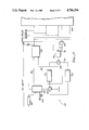
- FIG. 1 is a schematic view of one embodiment of the invention having a pair of adsorption/desorption beds.
- FIG. 2 is another embodiment of the invention similar to that of FIG. 1, but using cool air received from the confined area and further using an additional heat exchanger to heat the air going to the desorption bed and to cool the air going to the cooling packs.
- FIG. 3 is another embodiment of the invention similar to that of FIG. 1 except that the heat exchanger also receives the hot aircraft cabin trim air.
- FIG. 4 is still another embodiment of the invention similar to that of FIG. 1 except that the heat exchangers receiving air from the cooling packs are also used to cool the air directed to the adsorption bed.
- a first embodiment of the invention comprises an integrated thermal conditioning and purification system generally designated by the numeral 10.
- the invention includes preferably a pair of adsorption/desorption beds designated by the numerals 12 and 14 as shown.
- bed 12 is adsorbing CO 2 (or another impurity) from the incoming gas while bed 14 is preferably simultaneously desorbing CO 2 (or another impurity) from the gas mixture.
- Bed 12 preferably includes a carbon molecular sieve chemically treated to selectively adsorb CO 2 from the gas mixture.
- the carbon molecular sieve may, for example, be treated with an amine group of chemicals for selective adsorption of CO 2 .
- Cooling packs 16 receive fresh air, cool it to the desired temperature and direct it via conduit 17 through mix manifold 18 into an aircraft cabin or other confined area 28 via conduit 19. Air in the confined area 28 is drawn therefrom by recirculation fan 26 and directed via conduit 11 to bed 12 where CO 2 is adsorbed therefrom. Recirculation fan 26 also directs the air from the confined area 28 to the heat exchanger 20 which heats the air prior to it going to bed 14 via conduit 13 in order to regenerate bed 14. The temperature of the air going into bed 14 is preferably at a temperature no greater than 200° F. The air which has passed through bed 14 extracting the CO 2 impurities therefrom is purged from the system.
- Air which has passed through bed 12 which has removed the CO 2 impurities therefrom to the desired degree is directed to mix manifold 18 via conduit 15 where it is mixed with fresh air from the cooling pack and directed to the cabin 28.
- two 4-way valves 22 and 24 are provided to direct the flow of air (air to be purified or air to regenerate the bed) into the appropriate bed 12 or 14 or from the appropriate bed 12 or 14 as desired for purge purposes.
- one bed (12) is designated as the adsorbing bed and the other bed (14) is designated as the desorbing bed.
- FIG. 2 shows a second embodiment 110 of the invention which is similar to the embodiment of FIG. 1 except that it is specifically adapted for use in an aircraft and the heat exchanger 120 directly receives cabin air via conduit 111 and aircraft engine bleed air from bleed air source 146 via conduit 117.
- Heat exchanger 120 cools air going to the cooling packs 116 via conduit 121, and heats air going to desorbing bed 114 via conduit 113 to regenerate bed 114.
- Heat exchanger 120 may be integral with cooling packs 116 to utilize the heat extracted from the air going into mix manifold 118 to heat the air going to bed 114.
- a pair of recirculation fans 126 moves air directly from the adsorbing bed 112 to the mix manifold 118 and moves the air throughout the system.
- Conduit 115 communicatingly connects manifold 118 and bed 112.
- a controller 132 is provided to properly alternate adsorbing and desorbing airflow between the beds 112 and 114 in accordance with how much CO 2 the adsorbing bed 112 or 114 is removing from the air and/or how much CO 2 the desorbing bed 112 or 114 is putting back into the air.
- the controller 132 thus controls both valves 122 and 124 and has sensors 136 to sense the concentration of CO 2 in order to determine the proper cycling time for air moving through the beds 112 and 114.
- the sensors 136 are located to sense CO 2 concentration of the heated air going into the bed 114 and the airto be purified coming from the cabin 128 to monitor CO 2 concentration of cabin air (or sensor 136 can be located to directly sense CO 2 concentration of the air inside cabin 128). Suitably located temperature sensors may also be used to keep the air temperature within desired parameters.
- a computer 148 may also be connected to the controller 132 in order to further enhance efficiency and optimize system operation by processing data deemed important in determining proper cycling of airflow going to and from beds 112 and 114.
- particulate filters 140 are provided within the cabin to filter particulate impurities out of the air before going to the bed 112 via conduit 111.
- a pressure transducer 150 analogous to transducer 350 of FIG.
- cooling packs 116 receive bleed air from source 146 via conduit 117, cool the air and direct it to mix manifold 118 via conduit 119.
- sorbent beds and valves 122 and 124 and their operation in system 110 are essentially similar to those of embodiment 10.
- FIG. 3 shows a third embodiment 210 of the invention specifically adapted for use in purifying and thermally conditioning the air in an aircraft cabin.
- Embodiment 210 is quite similar to embodiment 10 except that hot trim air to the cabin 228 is directed to the heat exchanger 220 and from there to the cabin 228 at a somewhat lower temperature.
- the heat exchanger 220 extracts heat energy from the hot trim air and uses that heat energy to heat the air going into the desorbing bed 214.
- Heat exchanger 220 receives cabin air via conduit 211.
- Heat exchanger 220 directs heated air into bed 214 via conduit 213 for desorption.
- Heat exchanger 244 receives both cabin air via conduit 211 and cooled air from cooling pack 2l6, further cools and directs it to bed 212 for adsorption.
- the air from bed 212 is directed via conduit 215 to mix manifold 218.
- Mix manifold 218 also receives cooled air from heat exchanger 244 and directs both this cooled air from exchanger 244 and purified air from bed 212 into cabin 228.
- FIG. 3 shows auxiliary ram air from ram air source 242 being received by heat exchanger 244.
- cooling pack 216, 4-way valves 222 and 224, and fan 226 and, their operation in embodiment 210 are essentially similar to those of embodiment 10.
- FIG. 4 shows still another embodiment 310 of the invention wherein the cooling packs 316 are more efficiently utilized to provide both the cooling and the heating required for the adsorption-desorption process of the beds.
- the heat exchangers 344 used with the cooling packs 316 are used to cool, from conduit 311, the incoming air to be purified going into the adsorption bed 312.
- the bleed air coming from the aircraft engine bleed air source 346 is also directed into a heat exchanger 320 via conduit 317 which feeds hot air into the desorption bed 314 via conduit 313 for regeneration of the same.
- this additional heat exchanger 320 also provides cooler air going into the cooling pack 316 via conduit 321.
- a heat exchanger 346 receives hot regenerating air from the desorbing bed 314, extracts heat energy from the regenerating air and purges it from the system 310. The extracted heat energy is used in heating the regenerating air going into desorbing bed 314 from heat exchanger 320.
- Mix manifold 318 has the same function as manifold 218 of mixing purified and recirculated air from conduit 315 with fresh air from conduit 319 to transmit the same into the cabin 328.
- Particulate filters 340 are used to draw cleaner air out of the cabin 328.
- Pressure transducer 350 is also provided at filter 340 for its operation. Controller 332 also is used to control the valves 322 and 324 to cycle the adsorption-desorption flow.
- Computer 348 is operably connected to controller 332 to process data for enhanced efficiency of the cycling. Cooling packs 316, heat exchaners 320 and 344 and recirculation fans 326 also are provided to perform essentially the same functions as pack 216, exchangers 220 and 244 and fans 226 in embodiment 210. In all other important respects this embodiment 310 is similar to embodiment 210.
- adsorption/desorption systems can also be used with the invention as described.
- activated carbon or zeolite molecular sieve beds or any such other type of adsorption/desorption bed using temperature swing can be used.
- the beds can also be composed of a suitable composite material instead of just pure carbon.
- the controller described hereinabove may simply be a timer which alternates flow of the adsorbing and desorbing flow to the appropriate beds based on a selected time interval which is deemed suitable for appropriate cycling of the desorption and adsorption air flows.
- the time interval is based on the desired CO 2 concentration of the purified air or other requirements of the particular use to which the system is put.
- the adsorption process may take place at approximately room temperature. However, it is preferable that the adsorption take place at a somewhat lower temperature than this because the lower the temperature the stronger the bond between the CO 2 and the chemically treated carbon. Thus, the lower the temperature of the adsorbent airflow the better. However, the maximum temperature at which desorption takes place should not be greater than 200° F. and preferably is much lower. Thus, the difference between the required upper temperature limit and the required lower temperature limit is not great. This small temperature difference results in a relatively efficient low energy adsorption system.
Abstract
Description
Claims (24)
Priority Applications (1)
| Application Number | Priority Date | Filing Date | Title |
|---|---|---|---|
| US07/135,872 US4786294A (en) | 1987-12-21 | 1987-12-21 | Integrated gas purification and thermal conditioning system utilizing molecular sieve adsorption |
Applications Claiming Priority (1)
| Application Number | Priority Date | Filing Date | Title |
|---|---|---|---|
| US07/135,872 US4786294A (en) | 1987-12-21 | 1987-12-21 | Integrated gas purification and thermal conditioning system utilizing molecular sieve adsorption |
Publications (1)
| Publication Number | Publication Date |
|---|---|
| US4786294A true US4786294A (en) | 1988-11-22 |
Family
ID=22470114
Family Applications (1)
| Application Number | Title | Priority Date | Filing Date |
|---|---|---|---|
| US07/135,872 Expired - Lifetime US4786294A (en) | 1987-12-21 | 1987-12-21 | Integrated gas purification and thermal conditioning system utilizing molecular sieve adsorption |
Country Status (1)
| Country | Link |
|---|---|
| US (1) | US4786294A (en) |
Cited By (25)
| Publication number | Priority date | Publication date | Assignee | Title |
|---|---|---|---|---|
| US5269834A (en) * | 1992-10-13 | 1993-12-14 | Olin Corporation | Process for removal of inert gases from liquid chlorine and system therefor |
| US5294410A (en) * | 1992-06-01 | 1994-03-15 | Solar Turbine Incorporated | Gas purification and conditioning system |
| US5298054A (en) * | 1990-10-01 | 1994-03-29 | Fmc Corporation | Pressure and temperature swing adsorption system |
| EP0648671A1 (en) * | 1993-10-15 | 1995-04-19 | DaimlerChrysler Aerospace Airbus Gesellschaft mit beschränkter Haftung | Cabin air circulation system for the air conditioning of an aircraft passagers zones |
| US5531220A (en) * | 1993-03-10 | 1996-07-02 | Pall Corporation | Gas supply systems |
| US6065473A (en) * | 1997-06-16 | 2000-05-23 | Airsep Corporation | Non-contact gas dispenser and apparatus for use therewith |
| US6425946B1 (en) | 2000-12-26 | 2002-07-30 | Matheson Tri-Gas, Inc. | Method and apparatus for removing trace impurities from a gas using superactivated carbon material |
| US20030024390A1 (en) * | 2000-12-26 | 2003-02-06 | Funke Hans H. | Method and apparatus for removing trace impurities from inert, non-reactive and reactive liquids |
| US6610122B1 (en) * | 2002-04-30 | 2003-08-26 | Hamilton Sundstrand Corp. | Water recuperation for a carbon dioxide (CO2) removal system |
| US6656878B2 (en) | 1998-03-09 | 2003-12-02 | Honeywell International Inc. | High capacity adsorbent for oxygen storage at cryogenic temperature |
| EP1273515A3 (en) * | 2001-07-05 | 2004-05-12 | Shimadzu Corporation | Aircraft air conditioner |
| US20040112211A1 (en) * | 2002-11-26 | 2004-06-17 | Udi Meirav | Oxygen enrichment of indoor human environments |
| US6908497B1 (en) * | 2003-04-23 | 2005-06-21 | The United States Of America As Represented By The Department Of Energy | Solid sorbents for removal of carbon dioxide from gas streams at low temperatures |
| US20090260372A1 (en) * | 2008-04-18 | 2009-10-22 | Hunter Manufacturing Co. | Systems and methods of heating, cooling and humidity control in air filtration adsorbent beds |
| US9180401B2 (en) | 2011-01-20 | 2015-11-10 | Saudi Arabian Oil Company | Liquid, slurry and flowable powder adsorption/absorption method and system utilizing waste heat for on-board recovery and storage of CO2 from motor vehicle internal combustion engine exhaust gases |
| US9297285B2 (en) | 2011-01-20 | 2016-03-29 | Saudi Arabian Oil Company | Direct densification method and system utilizing waste heat for on-board recovery and storage of CO2 from motor vehicle internal combustion engine exhaust gases |
| US9371755B2 (en) | 2011-01-20 | 2016-06-21 | Saudi Arabian Oil Company | Membrane separation method and system utilizing waste heat for on-board recovery and storage of CO2 from motor vehicle internal combustion engine exhaust gases |
| US20160318613A1 (en) * | 2015-04-29 | 2016-11-03 | Honeywell International Inc. | Combined voc-o2-co2 treatment system |
| US9581062B2 (en) | 2011-01-20 | 2017-02-28 | Saudi Arabian Oil Company | Reversible solid adsorption method and system utilizing waste heat for on-board recovery and storage of CO2 from motor vehicle internal combustion engine exhaust gases |
| WO2017064209A3 (en) * | 2015-10-14 | 2017-05-26 | Eaton Limited | Fuel tank inerting system |
| US20180272277A1 (en) * | 2017-03-23 | 2018-09-27 | CleanO2 Carbon Capture Technologies Inc. | Flue gas carbon and heat capture and recirculation system |
| US10106272B2 (en) | 2015-06-29 | 2018-10-23 | Parker-Hannifin Corporation | Regenerative activated carbon filtration for aircraft OBIGGS |
| US10174943B2 (en) | 2012-12-31 | 2019-01-08 | Inventys Thermal Technologies Inc. | System and method for integrated carbon dioxide gas separation from combustion gases |
| US20190041145A1 (en) * | 2017-08-01 | 2019-02-07 | Hamilton Sundstrand Corporation | Three-way modulating valve for temperature control |
| US10981655B2 (en) | 2018-11-21 | 2021-04-20 | Hamilton Sundstrand Corporation | Carbon dioxide adsorber for aircraft |
Citations (39)
| Publication number | Priority date | Publication date | Assignee | Title |
|---|---|---|---|---|
| US2545194A (en) * | 1945-11-14 | 1951-03-13 | Allan P Colburn | Adsorption process for removal of carbon dioxide from the atmosphere of a submarine |
| US2818323A (en) * | 1953-10-07 | 1957-12-31 | Universal Oil Prod Co | Purification of gases with an amine impregnated solid absorbent |
| US3104162A (en) * | 1960-05-18 | 1963-09-17 | Exxon Research Engineering Co | Timing cycle for improved heatless fractionation of gaseous materials |
| FR1360112A (en) * | 1962-06-09 | 1964-04-30 | Lindes Eismasch Ag | Process and installation for the removal of carbon dioxide from gas mixtures which contain it |
| US3196596A (en) * | 1961-12-19 | 1965-07-27 | Pure Oil Co | Method for absorption of carbon dioxide |
| US3242651A (en) * | 1961-04-24 | 1966-03-29 | United Aircraft Corp | Purification system with equalizing valve |
| US3355860A (en) * | 1965-02-18 | 1967-12-05 | United Aircraft Corp | Three canister regenerative co2 system |
| US3469934A (en) * | 1964-10-26 | 1969-09-30 | Girdler Corp | Method of purifying closed atmospheres |
| US3491031A (en) * | 1966-11-18 | 1970-01-20 | Calgon C0Rp | Reactivation of monoethanolamine impregnated activated carbon |
| US3497312A (en) * | 1964-01-23 | 1970-02-24 | Us Navy | Atmosphere regeneration method for closed environmental vehicles |
| DE1619855B1 (en) * | 1967-09-09 | 1970-08-27 | Ceag Concordia Elek Zitaets Ag | Method and device for removing acidic components from gases |
| US3659400A (en) * | 1970-07-21 | 1972-05-02 | United Aircraft Corp | Carbon dioxide removal from breathable atmospheres |
| US3729902A (en) * | 1968-08-27 | 1973-05-01 | F Ventriglio | Carbon dioxide sorbent for confined breathing atmospheres |
| US3891411A (en) * | 1972-12-13 | 1975-06-24 | Babcock & Wilcox Ag | Method and apparatus for the production of nitrogen for use as an inert gas |
| US3960522A (en) * | 1971-04-23 | 1976-06-01 | Bergwerksverband Gmbh | Carbon-containing molecular sieves |
| DE2531633A1 (en) * | 1975-07-15 | 1977-01-20 | Wilkerson Corp | Drying of gases esp. compressed air - using heat exchanger delivering stream at constant pressure lower than that of supply pressure for instrument system |
| US4005708A (en) * | 1974-04-29 | 1977-02-01 | A-T-O Inc. | Apparatus for endothermal absorption of carbon dioxide |
| US4012206A (en) * | 1972-12-02 | 1977-03-15 | Gas Developments Corporation | Air cleaning adsorption process |
| US4030896A (en) * | 1975-04-14 | 1977-06-21 | Linde Aktiengesellschaft | Regeneration of adsorbents |
| US4046709A (en) * | 1974-06-20 | 1977-09-06 | Director-General Of The Agency Of Industrial Science And Technology | Method of manufacturing carbonaceous granular molecular sieve |
| US4165972A (en) * | 1977-10-03 | 1979-08-28 | The United States Of America As Represented By The Secretary Of The Navy | Gas separating system |
| US4197095A (en) * | 1978-08-31 | 1980-04-08 | Pall Corporation | Heatless adsorbent fractionators with microprocessor cycle control and process |
| SU762943A1 (en) * | 1977-07-18 | 1980-09-15 | Vni Pi Podgotovke K Transporti | Method of purifying gases from acid components |
| US4222750A (en) * | 1976-08-16 | 1980-09-16 | Champion Spark Plug Company | Oxygen enrichment system for medical use |
| US4336159A (en) * | 1979-09-12 | 1982-06-22 | Ceag Verfahrenstechnik Gmbh | Method and arrangement for the thermal regeneration of charged adsorption materials |
| US4420415A (en) * | 1980-08-27 | 1983-12-13 | Director-General Of Agency Of Industrial Science & Technology | Process for the production of carbon molecular sieves |
| US4472178A (en) * | 1983-07-05 | 1984-09-18 | Air Products And Chemicals, Inc. | Adsorptive process for the removal of carbon dioxide from a gas |
| US4511375A (en) * | 1984-03-29 | 1985-04-16 | Union Carbide Corporation | Process and apparatus for direct heat transfer temperature swing regeneration |
| US4526887A (en) * | 1983-03-16 | 1985-07-02 | Calgon Carbon Corporation | Carbon molecular sieves and a process for their preparation and use |
| US4533365A (en) * | 1982-07-17 | 1985-08-06 | Kernforschungsanlage Julich Gesellschaft Mit Beschrankter Haftung | Process for the separation and recycling of NOx gas constituents through adsorption and desorption on a molecular sieve |
| US4540678A (en) * | 1982-09-07 | 1985-09-10 | Calgon Carbon Corporation | Carbon molecular sieves and a process for their preparation and use |
| WO1986002010A1 (en) * | 1984-09-28 | 1986-04-10 | Sumsky Filial Kharkovskogo Politekhnicheskogo Inst | Device for throwing tennis balls |
| US4589896A (en) * | 1985-01-28 | 1986-05-20 | Air Products And Chemicals, Inc. | Process for separating CO2 and H2 S from hydrocarbons |
| US4589890A (en) * | 1985-01-10 | 1986-05-20 | Dedert Corporation | Heat recovery method and apparatus |
| JPS61227822A (en) * | 1985-04-01 | 1986-10-09 | Kawasaki Heavy Ind Ltd | Removing device for carbonic acid gas |
| US4661124A (en) * | 1981-11-13 | 1987-04-28 | Normalair-Garrett (Holding) Limited | Molecular sieve type gas separation systems |
| US4698073A (en) * | 1983-10-06 | 1987-10-06 | Linde Aktiengesellschaft | Process for regeneration of adsorbers |
| US4732579A (en) * | 1986-04-14 | 1988-03-22 | Fmc Corporation | Air purification and temperature controlling system and method |
| US4738694A (en) * | 1985-04-25 | 1988-04-19 | L'air Liquide Societe Anonyme Pour L'etude Et L'exploitation Des Procedes Georges Claude | Process and plant for purification by adsorption on activated carbon and corresponding adsorber vessel |
-
1987
- 1987-12-21 US US07/135,872 patent/US4786294A/en not_active Expired - Lifetime
Patent Citations (39)
| Publication number | Priority date | Publication date | Assignee | Title |
|---|---|---|---|---|
| US2545194A (en) * | 1945-11-14 | 1951-03-13 | Allan P Colburn | Adsorption process for removal of carbon dioxide from the atmosphere of a submarine |
| US2818323A (en) * | 1953-10-07 | 1957-12-31 | Universal Oil Prod Co | Purification of gases with an amine impregnated solid absorbent |
| US3104162A (en) * | 1960-05-18 | 1963-09-17 | Exxon Research Engineering Co | Timing cycle for improved heatless fractionation of gaseous materials |
| US3242651A (en) * | 1961-04-24 | 1966-03-29 | United Aircraft Corp | Purification system with equalizing valve |
| US3196596A (en) * | 1961-12-19 | 1965-07-27 | Pure Oil Co | Method for absorption of carbon dioxide |
| FR1360112A (en) * | 1962-06-09 | 1964-04-30 | Lindes Eismasch Ag | Process and installation for the removal of carbon dioxide from gas mixtures which contain it |
| US3497312A (en) * | 1964-01-23 | 1970-02-24 | Us Navy | Atmosphere regeneration method for closed environmental vehicles |
| US3469934A (en) * | 1964-10-26 | 1969-09-30 | Girdler Corp | Method of purifying closed atmospheres |
| US3355860A (en) * | 1965-02-18 | 1967-12-05 | United Aircraft Corp | Three canister regenerative co2 system |
| US3491031A (en) * | 1966-11-18 | 1970-01-20 | Calgon C0Rp | Reactivation of monoethanolamine impregnated activated carbon |
| DE1619855B1 (en) * | 1967-09-09 | 1970-08-27 | Ceag Concordia Elek Zitaets Ag | Method and device for removing acidic components from gases |
| US3729902A (en) * | 1968-08-27 | 1973-05-01 | F Ventriglio | Carbon dioxide sorbent for confined breathing atmospheres |
| US3659400A (en) * | 1970-07-21 | 1972-05-02 | United Aircraft Corp | Carbon dioxide removal from breathable atmospheres |
| US3960522A (en) * | 1971-04-23 | 1976-06-01 | Bergwerksverband Gmbh | Carbon-containing molecular sieves |
| US4012206A (en) * | 1972-12-02 | 1977-03-15 | Gas Developments Corporation | Air cleaning adsorption process |
| US3891411A (en) * | 1972-12-13 | 1975-06-24 | Babcock & Wilcox Ag | Method and apparatus for the production of nitrogen for use as an inert gas |
| US4005708A (en) * | 1974-04-29 | 1977-02-01 | A-T-O Inc. | Apparatus for endothermal absorption of carbon dioxide |
| US4046709A (en) * | 1974-06-20 | 1977-09-06 | Director-General Of The Agency Of Industrial Science And Technology | Method of manufacturing carbonaceous granular molecular sieve |
| US4030896A (en) * | 1975-04-14 | 1977-06-21 | Linde Aktiengesellschaft | Regeneration of adsorbents |
| DE2531633A1 (en) * | 1975-07-15 | 1977-01-20 | Wilkerson Corp | Drying of gases esp. compressed air - using heat exchanger delivering stream at constant pressure lower than that of supply pressure for instrument system |
| US4222750A (en) * | 1976-08-16 | 1980-09-16 | Champion Spark Plug Company | Oxygen enrichment system for medical use |
| SU762943A1 (en) * | 1977-07-18 | 1980-09-15 | Vni Pi Podgotovke K Transporti | Method of purifying gases from acid components |
| US4165972A (en) * | 1977-10-03 | 1979-08-28 | The United States Of America As Represented By The Secretary Of The Navy | Gas separating system |
| US4197095A (en) * | 1978-08-31 | 1980-04-08 | Pall Corporation | Heatless adsorbent fractionators with microprocessor cycle control and process |
| US4336159A (en) * | 1979-09-12 | 1982-06-22 | Ceag Verfahrenstechnik Gmbh | Method and arrangement for the thermal regeneration of charged adsorption materials |
| US4420415A (en) * | 1980-08-27 | 1983-12-13 | Director-General Of Agency Of Industrial Science & Technology | Process for the production of carbon molecular sieves |
| US4661124A (en) * | 1981-11-13 | 1987-04-28 | Normalair-Garrett (Holding) Limited | Molecular sieve type gas separation systems |
| US4533365A (en) * | 1982-07-17 | 1985-08-06 | Kernforschungsanlage Julich Gesellschaft Mit Beschrankter Haftung | Process for the separation and recycling of NOx gas constituents through adsorption and desorption on a molecular sieve |
| US4540678A (en) * | 1982-09-07 | 1985-09-10 | Calgon Carbon Corporation | Carbon molecular sieves and a process for their preparation and use |
| US4526887A (en) * | 1983-03-16 | 1985-07-02 | Calgon Carbon Corporation | Carbon molecular sieves and a process for their preparation and use |
| US4472178A (en) * | 1983-07-05 | 1984-09-18 | Air Products And Chemicals, Inc. | Adsorptive process for the removal of carbon dioxide from a gas |
| US4698073A (en) * | 1983-10-06 | 1987-10-06 | Linde Aktiengesellschaft | Process for regeneration of adsorbers |
| US4511375A (en) * | 1984-03-29 | 1985-04-16 | Union Carbide Corporation | Process and apparatus for direct heat transfer temperature swing regeneration |
| WO1986002010A1 (en) * | 1984-09-28 | 1986-04-10 | Sumsky Filial Kharkovskogo Politekhnicheskogo Inst | Device for throwing tennis balls |
| US4589890A (en) * | 1985-01-10 | 1986-05-20 | Dedert Corporation | Heat recovery method and apparatus |
| US4589896A (en) * | 1985-01-28 | 1986-05-20 | Air Products And Chemicals, Inc. | Process for separating CO2 and H2 S from hydrocarbons |
| JPS61227822A (en) * | 1985-04-01 | 1986-10-09 | Kawasaki Heavy Ind Ltd | Removing device for carbonic acid gas |
| US4738694A (en) * | 1985-04-25 | 1988-04-19 | L'air Liquide Societe Anonyme Pour L'etude Et L'exploitation Des Procedes Georges Claude | Process and plant for purification by adsorption on activated carbon and corresponding adsorber vessel |
| US4732579A (en) * | 1986-04-14 | 1988-03-22 | Fmc Corporation | Air purification and temperature controlling system and method |
Cited By (51)
| Publication number | Priority date | Publication date | Assignee | Title |
|---|---|---|---|---|
| US5298054A (en) * | 1990-10-01 | 1994-03-29 | Fmc Corporation | Pressure and temperature swing adsorption system |
| US5294410A (en) * | 1992-06-01 | 1994-03-15 | Solar Turbine Incorporated | Gas purification and conditioning system |
| US5269834A (en) * | 1992-10-13 | 1993-12-14 | Olin Corporation | Process for removal of inert gases from liquid chlorine and system therefor |
| US5531220A (en) * | 1993-03-10 | 1996-07-02 | Pall Corporation | Gas supply systems |
| US5642729A (en) * | 1993-03-10 | 1997-07-01 | Pall Corporation | Gas supply systems |
| EP0648671A1 (en) * | 1993-10-15 | 1995-04-19 | DaimlerChrysler Aerospace Airbus Gesellschaft mit beschränkter Haftung | Cabin air circulation system for the air conditioning of an aircraft passagers zones |
| US6065473A (en) * | 1997-06-16 | 2000-05-23 | Airsep Corporation | Non-contact gas dispenser and apparatus for use therewith |
| US6656878B2 (en) | 1998-03-09 | 2003-12-02 | Honeywell International Inc. | High capacity adsorbent for oxygen storage at cryogenic temperature |
| US6783576B2 (en) | 2000-12-26 | 2004-08-31 | Matheson Tri-Gas, Inc. | Gas purifier system for removing trace impurities from a reactive fluid |
| US6709482B2 (en) | 2000-12-26 | 2004-03-23 | Matheson Tri-Gas, Inc. | Method for reducing trace impurities from a reactive fluid using preconditioned ultra-low emission carbon material |
| US20030024396A1 (en) * | 2000-12-26 | 2003-02-06 | Funke Hans H. | Gas purifier system containing an ultra-low emission carbon material |
| US20030024394A1 (en) * | 2000-12-26 | 2003-02-06 | Funke Hans H. | Method for producing a preconditioned ultra-low emmission carbon material |
| US20030024395A1 (en) * | 2000-12-26 | 2003-02-06 | Funke Hans H. | Gas purifier system for removing trace impurities from a reactive fluid |
| US20030033936A1 (en) * | 2000-12-26 | 2003-02-20 | Funke Hans H. | Method for removing impurities from process gas stream |
| US20030041734A1 (en) * | 2000-12-26 | 2003-03-06 | Funke Hans H. | Method for producing an ultra-low emission carbon material |
| US6547861B2 (en) | 2000-12-26 | 2003-04-15 | Matheson Tri-Gas,, Inc. | Method and materials for purifying reactive gases using preconditioned ultra-low emission carbon material |
| US6797036B2 (en) | 2000-12-26 | 2004-09-28 | Matheson Tri-Gas, Inc. | Method for removing impurities from process gas stream |
| US20030024390A1 (en) * | 2000-12-26 | 2003-02-06 | Funke Hans H. | Method and apparatus for removing trace impurities from inert, non-reactive and reactive liquids |
| US6710012B2 (en) | 2000-12-26 | 2004-03-23 | Matheson Tri-Gas, Inc, | Method for producing an ultra-low emission carbon material |
| US20030024391A1 (en) * | 2000-12-26 | 2003-02-06 | Funke Hans H. | Method for reducing trace impurities from a reactive fluid using preconditioned ultra-low emission carbon material |
| US6720282B2 (en) | 2000-12-26 | 2004-04-13 | Matheson Tri-Gas, Inc. | Method for producing a preconditioned ultra-low emission carbon material |
| US6790358B2 (en) | 2000-12-26 | 2004-09-14 | Matheson Tri-Gas, Inc. | Composition for removing trace impurities from inert, non-reactive and reactive liquids |
| US6425946B1 (en) | 2000-12-26 | 2002-07-30 | Matheson Tri-Gas, Inc. | Method and apparatus for removing trace impurities from a gas using superactivated carbon material |
| US6783577B2 (en) | 2000-12-26 | 2004-08-31 | Matheson Tri-Gas, Inc. | Gas purifier system containing an ultra-low emission carbon material |
| EP1273515A3 (en) * | 2001-07-05 | 2004-05-12 | Shimadzu Corporation | Aircraft air conditioner |
| US6610122B1 (en) * | 2002-04-30 | 2003-08-26 | Hamilton Sundstrand Corp. | Water recuperation for a carbon dioxide (CO2) removal system |
| US20040112211A1 (en) * | 2002-11-26 | 2004-06-17 | Udi Meirav | Oxygen enrichment of indoor human environments |
| US6866701B2 (en) * | 2002-11-26 | 2005-03-15 | Udi Meirav | Oxygen enrichment of indoor human environments |
| US6908497B1 (en) * | 2003-04-23 | 2005-06-21 | The United States Of America As Represented By The Department Of Energy | Solid sorbents for removal of carbon dioxide from gas streams at low temperatures |
| US20090260372A1 (en) * | 2008-04-18 | 2009-10-22 | Hunter Manufacturing Co. | Systems and methods of heating, cooling and humidity control in air filtration adsorbent beds |
| WO2009137261A3 (en) * | 2008-04-18 | 2009-12-30 | Hunter Manufacturing Co. | Systems and methods of heating, cooling and humidity control in air filtration adsorbent beds |
| US9180401B2 (en) | 2011-01-20 | 2015-11-10 | Saudi Arabian Oil Company | Liquid, slurry and flowable powder adsorption/absorption method and system utilizing waste heat for on-board recovery and storage of CO2 from motor vehicle internal combustion engine exhaust gases |
| US9297285B2 (en) | 2011-01-20 | 2016-03-29 | Saudi Arabian Oil Company | Direct densification method and system utilizing waste heat for on-board recovery and storage of CO2 from motor vehicle internal combustion engine exhaust gases |
| US9371755B2 (en) | 2011-01-20 | 2016-06-21 | Saudi Arabian Oil Company | Membrane separation method and system utilizing waste heat for on-board recovery and storage of CO2 from motor vehicle internal combustion engine exhaust gases |
| US9581062B2 (en) | 2011-01-20 | 2017-02-28 | Saudi Arabian Oil Company | Reversible solid adsorption method and system utilizing waste heat for on-board recovery and storage of CO2 from motor vehicle internal combustion engine exhaust gases |
| US10174943B2 (en) | 2012-12-31 | 2019-01-08 | Inventys Thermal Technologies Inc. | System and method for integrated carbon dioxide gas separation from combustion gases |
| US11378274B2 (en) | 2012-12-31 | 2022-07-05 | Svante Inc. | System and method for integrated carbon dioxide gas separation from combustion gases |
| US10507927B2 (en) * | 2015-04-29 | 2019-12-17 | Honeywell International Inc. | Combined VOC-O2—CO2 treatment system |
| US10017257B2 (en) * | 2015-04-29 | 2018-07-10 | Honeywell International Inc. | Combined VOC—O2—CO2 treatment system |
| US20180265204A1 (en) * | 2015-04-29 | 2018-09-20 | Honeywell International Inc. | Combined voc-02-co2 treatment system |
| US20160318613A1 (en) * | 2015-04-29 | 2016-11-03 | Honeywell International Inc. | Combined voc-o2-co2 treatment system |
| EP3090950A1 (en) * | 2015-04-29 | 2016-11-09 | Honeywell International Inc. | Combined voc-o2-co2 treatment system |
| US10207813B1 (en) | 2015-06-29 | 2019-02-19 | Parker-Hannifin Corporation | Regenerative activated carbon filtration for aircraft obiggs |
| US10106272B2 (en) | 2015-06-29 | 2018-10-23 | Parker-Hannifin Corporation | Regenerative activated carbon filtration for aircraft OBIGGS |
| WO2017064209A3 (en) * | 2015-10-14 | 2017-05-26 | Eaton Limited | Fuel tank inerting system |
| US10633110B2 (en) | 2015-10-14 | 2020-04-28 | Eaton Intelligent Power Limited | Fuel tank inerting system |
| US10537851B2 (en) * | 2017-03-23 | 2020-01-21 | CleanO2 Carbon Capture Technologies Inc. | Flue gas carbon and heat capture and recirculation system |
| US20180272277A1 (en) * | 2017-03-23 | 2018-09-27 | CleanO2 Carbon Capture Technologies Inc. | Flue gas carbon and heat capture and recirculation system |
| US20190041145A1 (en) * | 2017-08-01 | 2019-02-07 | Hamilton Sundstrand Corporation | Three-way modulating valve for temperature control |
| US11519680B2 (en) | 2017-08-01 | 2022-12-06 | Hamilton Sundstrand Corporation | Three-way modulating valve for temperature control |
| US10981655B2 (en) | 2018-11-21 | 2021-04-20 | Hamilton Sundstrand Corporation | Carbon dioxide adsorber for aircraft |
Similar Documents
| Publication | Publication Date | Title |
|---|---|---|
| US4786294A (en) | Integrated gas purification and thermal conditioning system utilizing molecular sieve adsorption | |
| US4793832A (en) | Air purification and temperature controlling system and method | |
| US4732579A (en) | Air purification and temperature controlling system and method | |
| US4822383A (en) | Method and apparatus for removing carbon dioxide from air | |
| EP1964601B1 (en) | Thermally linked molecular sieve beds for CO2 removal | |
| JP2598690B2 (en) | Environmental control device | |
| US5061455A (en) | Apparatus for removing carbon dioxide from air | |
| US11560817B2 (en) | System and method for mobile carbon capture | |
| EP2468384A1 (en) | Method and system for carbon dioxide removal | |
| US6099617A (en) | Air environment control systems | |
| US3221477A (en) | Space adsorption system and method | |
| US5453112A (en) | Pressure swing adsorption heat recovery | |
| JPH1057744A (en) | Multi-heat-pulse type psa system | |
| EP0830263B1 (en) | Air conditioning system | |
| US7125439B2 (en) | Air environment control system and technique | |
| RU2097115C1 (en) | System for removing carbon dioxide from air | |
| US10981655B2 (en) | Carbon dioxide adsorber for aircraft | |
| JP2796416B2 (en) | Carbon dioxide removal equipment | |
| KR100306428B1 (en) | Isostatic Moving Bed Continuous Purifier | |
| CN209596862U (en) | Low concentration VOCs gas purge system | |
| JP2003160098A5 (en) | ||
| KR920703178A (en) | Pressure and temperature swing adsorption system | |
| JP2580267B2 (en) | Air conditioning system with oxygen enrichment function | |
| JP2003160098A (en) | Air conditioner for aircraft | |
| JPH11319458A (en) | Pretreating device in air separation device |
Legal Events
| Date | Code | Title | Description |
|---|---|---|---|
| AS | Assignment |
Owner name: ALLIED-SIGNAL INC., 9851 SEPULVEDA BLVD. P.O. BOX Free format text: ASSIGNMENT OF ASSIGNORS INTEREST.;ASSIGNORS:JONQUERES, MICHEL A.;KAY, ROBERT J.;REEL/FRAME:004821/0113 Effective date: 19880121 Owner name: ALLIED-SIGNAL INC., A DE. CORP.,CALIFORNIA Free format text: ASSIGNMENT OF ASSIGNORS INTEREST;ASSIGNORS:JONQUERES, MICHEL A.;KAY, ROBERT J.;REEL/FRAME:004821/0113 Effective date: 19880121 |
|
| STCF | Information on status: patent grant |
Free format text: PATENTED CASE |
|
| FEPP | Fee payment procedure |
Free format text: PAYOR NUMBER ASSIGNED (ORIGINAL EVENT CODE: ASPN); ENTITY STATUS OF PATENT OWNER: LARGE ENTITY |
|
| FPAY | Fee payment |
Year of fee payment: 4 |
|
| FEPP | Fee payment procedure |
Free format text: PAYER NUMBER DE-ASSIGNED (ORIGINAL EVENT CODE: RMPN); ENTITY STATUS OF PATENT OWNER: LARGE ENTITY |
|
| FPAY | Fee payment |
Year of fee payment: 8 |
|
| FEPP | Fee payment procedure |
Free format text: PAYOR NUMBER ASSIGNED (ORIGINAL EVENT CODE: ASPN); ENTITY STATUS OF PATENT OWNER: LARGE ENTITY |
|
| FPAY | Fee payment |
Year of fee payment: 12 |