US4786090A - Peaked-top resilient seal ring and connection therewith - Google Patents
Peaked-top resilient seal ring and connection therewith Download PDFInfo
- Publication number
- US4786090A US4786090A US06/937,683 US93768386A US4786090A US 4786090 A US4786090 A US 4786090A US 93768386 A US93768386 A US 93768386A US 4786090 A US4786090 A US 4786090A
- Authority
- US
- United States
- Prior art keywords
- connection
- pin
- seal ring
- box
- groove
- Prior art date
- Legal status (The legal status is an assumption and is not a legal conclusion. Google has not performed a legal analysis and makes no representation as to the accuracy of the status listed.)
- Expired - Lifetime
Links
- 239000002184 metal Substances 0.000 claims abstract description 12
- 239000004810 polytetrafluoroethylene Substances 0.000 claims description 4
- 229920001343 polytetrafluoroethylene Polymers 0.000 claims description 4
- 239000000835 fiber Substances 0.000 claims description 3
- 230000013011 mating Effects 0.000 claims description 3
- 239000011152 fibreglass Substances 0.000 claims description 2
- 238000007789 sealing Methods 0.000 abstract description 17
- 238000012360 testing method Methods 0.000 description 8
- 230000008878 coupling Effects 0.000 description 4
- 238000010168 coupling process Methods 0.000 description 4
- 238000005859 coupling reaction Methods 0.000 description 4
- 230000009471 action Effects 0.000 description 2
- 239000000463 material Substances 0.000 description 2
- OKTJSMMVPCPJKN-UHFFFAOYSA-N Carbon Chemical compound [C] OKTJSMMVPCPJKN-UHFFFAOYSA-N 0.000 description 1
- JZUFKLXOESDKRF-UHFFFAOYSA-N Chlorothiazide Chemical compound C1=C(Cl)C(S(=O)(=O)N)=CC2=C1NCNS2(=O)=O JZUFKLXOESDKRF-UHFFFAOYSA-N 0.000 description 1
- 230000006835 compression Effects 0.000 description 1
- 238000007906 compression Methods 0.000 description 1
- 239000012530 fluid Substances 0.000 description 1
- 229910002804 graphite Inorganic materials 0.000 description 1
- 239000010439 graphite Substances 0.000 description 1
- 230000006872 improvement Effects 0.000 description 1
- 238000012986 modification Methods 0.000 description 1
- 230000004048 modification Effects 0.000 description 1
- 238000005382 thermal cycling Methods 0.000 description 1
Images
Classifications
-
- F—MECHANICAL ENGINEERING; LIGHTING; HEATING; WEAPONS; BLASTING
- F16—ENGINEERING ELEMENTS AND UNITS; GENERAL MEASURES FOR PRODUCING AND MAINTAINING EFFECTIVE FUNCTIONING OF MACHINES OR INSTALLATIONS; THERMAL INSULATION IN GENERAL
- F16L—PIPES; JOINTS OR FITTINGS FOR PIPES; SUPPORTS FOR PIPES, CABLES OR PROTECTIVE TUBING; MEANS FOR THERMAL INSULATION IN GENERAL
- F16L15/00—Screw-threaded joints; Forms of screw-threads for such joints
- F16L15/001—Screw-threaded joints; Forms of screw-threads for such joints with conical threads
- F16L15/004—Screw-threaded joints; Forms of screw-threads for such joints with conical threads with axial sealings having at least one plastically deformable sealing surface
-
- E—FIXED CONSTRUCTIONS
- E21—EARTH DRILLING; MINING
- E21B—EARTH DRILLING, e.g. DEEP DRILLING; OBTAINING OIL, GAS, WATER, SOLUBLE OR MELTABLE MATERIALS OR A SLURRY OF MINERALS FROM WELLS
- E21B17/00—Drilling rods or pipes; Flexible drill strings; Kellies; Drill collars; Sucker rods; Cables; Casings; Tubings
- E21B17/02—Couplings; joints
- E21B17/08—Casing joints
-
- F—MECHANICAL ENGINEERING; LIGHTING; HEATING; WEAPONS; BLASTING
- F16—ENGINEERING ELEMENTS AND UNITS; GENERAL MEASURES FOR PRODUCING AND MAINTAINING EFFECTIVE FUNCTIONING OF MACHINES OR INSTALLATIONS; THERMAL INSULATION IN GENERAL
- F16L—PIPES; JOINTS OR FITTINGS FOR PIPES; SUPPORTS FOR PIPES, CABLES OR PROTECTIVE TUBING; MEANS FOR THERMAL INSULATION IN GENERAL
- F16L15/00—Screw-threaded joints; Forms of screw-threads for such joints
- F16L15/001—Screw-threaded joints; Forms of screw-threads for such joints with conical threads
- F16L15/003—Screw-threaded joints; Forms of screw-threads for such joints with conical threads with sealing rings
-
- F—MECHANICAL ENGINEERING; LIGHTING; HEATING; WEAPONS; BLASTING
- F16—ENGINEERING ELEMENTS AND UNITS; GENERAL MEASURES FOR PRODUCING AND MAINTAINING EFFECTIVE FUNCTIONING OF MACHINES OR INSTALLATIONS; THERMAL INSULATION IN GENERAL
- F16L—PIPES; JOINTS OR FITTINGS FOR PIPES; SUPPORTS FOR PIPES, CABLES OR PROTECTIVE TUBING; MEANS FOR THERMAL INSULATION IN GENERAL
- F16L15/00—Screw-threaded joints; Forms of screw-threads for such joints
- F16L15/04—Screw-threaded joints; Forms of screw-threads for such joints with additional sealings
Definitions
- This invention pertains to resilient seal rings employed in tubular connections and the connections employing such seal rings.
- High performance or premium tubular connections are normally designed not to leak and to retain both fluid and gas even under harsh operating conditions.
- the general configurations of the threads employed in such connections and the metallic conical surfaces adjacent the actual threads are often designed to provide suitable metal-to-metal seals that seal and do not leak, many thread connections also employ resilient seal rings in addition.
- total seal reliance is placed in such a ring, not just secondary or tertiary sealing reliance.
- connection to have a metal-to-metal conical seal occurring at a given location, e.g., on the forward end of the pin member, with the resilient seal ring being included in a groove therein. In such a location, the ring contacts the opposing or mating sealing surface of the box member.
- the box member can be the adjacent tubular section with the box threads incorporated into the end thereof or the box member can be a coupling have box threads. In either case, the sealing action between the pin member and the box member is similar.
- a connection can also seal in its threads.
- a resilient seal ring can be included in the Series 500 Type 563 connection of the Hydril Company, which connection features a single step tapered dovetail wedge thread design having a shallow taper, mis-matched angle, conical metal-to-metal seal.
- the conventional seal ring employed in such a location is rectangular in cross-section and snugly fits into the groove made therefor.
- the temperatures may be up to around 300° F.
- the pressures may be up to around 20,000 psi. There may be thermal cycling between a very hot condition and a relatively cooler one. There may be many break outs and make ups of the connection.
- a tubular connection comprises a pin member and a box member, the box member either being in the form of a box-type coupling or the box end of a tubular section.
- the connection may have a seal within the threads, have a seal at one or more of the conical surfaces adjacent the threads or have no metal-to-metal seal area at all.
- the area adjacent a thread set on the pin member preferably in the area on the forward portion thereof, which may or may not be a metal-to-metal seal area, includes a rectangular groove therein for receiving a resilient seal ring.
- This pin area generally has a shallow taper, usually on the order of 14° or less.
- the seal ring has a base usually parallel to its axis and the two adjacent radial sides that are accommodated by the groove.
- the fourth side of the ring's cross-section comes to a peak, preferably at respective angles of about 15° with respect to each of the ring sides.
- the crown of the peak is preferably flat or parallel to the base of the ring.
- the sides of the ring are slightly longer than the respective adjacent sides of the groove in which the ring is located in use.
- connection When the connection is made up, there is no sharp corner of the ring that comes into stabbing contact with the adjacent conical area of the box member. Therefore, there is no tendency for the ring to rub or crawl out of the groove. Moreover, when the connection is tightened, the forces on the ring are such that it is compressed generally into the groove to fill the area of the groove, rather than to be squeezed longitudinally to be between the pin area and box area adjacent the groove, as is sometimes the tendency with rectangularly shaped seal rings in the prior art.
- the ring itself and the connection including the ring are two aspects of the present invention.
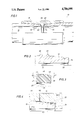
- FIG. 1 is a longitudinal cross-section of a typical tubular connection employing a resilient seal ring in accordance with the present invention.
- FIG. 2 is an enlargement of the longitudinal cross-section of the pin area employing a groove for receiving a resilient seal ring for use in a tubular connection in accordance with the present invention.
- FIG. 3 is a cross-sectional view of a preferred resilient seal ring in accordance with the present invention.
- FIG. 4 is a cross-sectional view of a test connection employing a resilient seal ring in accordance with the present invention, the test connection being useful in testing the effectiveness of the seal ring, wherein the conical metal-to-metal seal and the thread seal are defeated.
- FIG. 1 a tubular connection 10 is shown that includes the ends of pin member 12 and pin member 14 joined together in the connection by coupling 16.
- coupling 16 includes two box connections, one each for receiving the ends of pin member 12 and pin member 14.
- threads which are of the wedge type. Such threads become increasingly smaller in the box member as the threads helically progress away from the end of the box member and progressively larger as they helically progress away from the end of the pin member.
- connection sealing may be employed in the threads themselves, depending upon the dimensions of the threads, or on a conical sealing surface adjacent to the threads, or both.
- each of the conical members Located in the sealing surfaces of each of the conical members is a suitable rectangular groove 22 and 24, respectively, for accepting resilient seals 26 and 28, respectively, the configurations of the seal rings being described hereafter.
- the seal rings as well as the metal-to-metal sealing surfaces are independently designed to provide an effective pressure leakproof seal for the respective connections independently of any other seals which exist.
- pin member 12 an enlargement of pin member 12 is shown with the first two threads 30 and 32 of the thread set near the forward end of the pin member. Adjacent the thread set on the forward end of the pin member is conical sealing surface 18. Groove 22, previously described, is rectangular in nature and is shown cut into area 18 near the forward part of the sealing surface.
- the connection including pin member 14 with its accommodating box member is similar to the connection
- groove 22 is approximately 0.075 inches across and slightly under 0.025 inches deep.
- the rearward part of the groove is about 0.137 inches from the tip or nose end 34 of pin member 12.
- the base of the groove 22, the base being that portion of the groove which is parallel to the axis of the pin member, and each of the radial sides of the grooves, are nominally textured to 125 R a .
- the corners at the intersection of each of the radial sides with the base side include a slight radius.
- FIG. 3 a cross-sectional view of a resilient seal ring 26 is shown that is accommodated into groove 22 or 24.
- the base of the seal ring is approximately 0.010 inches less than the 0.075 inches dimension of the groove and the radial sides are approximately 0.025 inches.
- the ring is peaked on its fourth side to a dimension of about 0.006 inches.
- Chamfer sides 42 and 44 respectively angle from sides 38 and 40 and are each at an angle of about 15°.
- the crown at top surface 46 is preferably flat or parallel with base 36. This flat surface is only approximately 1/5th or so of the overall length of the side, however. Alternatively, the crown can be slightly rounded.
- FIG. 4 illustrates a test connection that was used in testing the efficacy of a groove and seal ring made in accordance with what has just been described.
- Pin member 12 is grooved on the side of groove 22 away from its tip or nose surface 34 to remove the metal-to-metal surface seal, as shown by area 50. This metal removal defeats the conical seal.
- a port 52 is made into box member 14 just in front of the first thread 30 of the pin member.
- resilient seal ring 26 A high, internal gas pressure of 19,600 psi and a net tension load of 208.6 kips was applied to the connection while the connection was thermally cycled between 100° F. and 300° F. At no time was a connection leak experienced using the seal mentioned.
- the material for the resilient seal ring that was employed in the test and preferred for ring 26 is approximately 15% fiberglass filled PTFE (1/32" long fibers). Alternatively, other fiber-filled materials such as graphite filled PTFE can be employed. The corners of the ring seal were all broken at 0.005 inch maximum radius.
- the radial sides of the ring are described as being preferably slightly longer than the radial sides of the groove, this is not necessary for a ring to function in the manner just described. That is, the sides of the ring and the sides of the groove can be approximately the same length, if desired. Moreover, the chamfer of sides 42 and 44 can be at a smaller or larger than 15° depending on the size of the seal ring and the taper of the related conical seal. The chamfer of the ring should be slightly greater than the conical sealing surfaces of the pin member and box member.
Abstract
Description
Claims (4)
Priority Applications (1)
| Application Number | Priority Date | Filing Date | Title |
|---|---|---|---|
| US06/937,683 US4786090A (en) | 1986-12-04 | 1986-12-04 | Peaked-top resilient seal ring and connection therewith |
Applications Claiming Priority (1)
| Application Number | Priority Date | Filing Date | Title |
|---|---|---|---|
| US06/937,683 US4786090A (en) | 1986-12-04 | 1986-12-04 | Peaked-top resilient seal ring and connection therewith |
Publications (1)
| Publication Number | Publication Date |
|---|---|
| US4786090A true US4786090A (en) | 1988-11-22 |
Family
ID=25470260
Family Applications (1)
| Application Number | Title | Priority Date | Filing Date |
|---|---|---|---|
| US06/937,683 Expired - Lifetime US4786090A (en) | 1986-12-04 | 1986-12-04 | Peaked-top resilient seal ring and connection therewith |
Country Status (1)
| Country | Link |
|---|---|
| US (1) | US4786090A (en) |
Cited By (22)
| Publication number | Priority date | Publication date | Assignee | Title |
|---|---|---|---|---|
| US5029906A (en) * | 1983-04-29 | 1991-07-09 | Baker Hughes Incorporated | Method and apparatus for forming a ventable seal |
| US5360240A (en) * | 1993-03-05 | 1994-11-01 | Hydril Company | Method of connecting plastic pipe joints to form a liner for an existing pipeline and a plastic pipe joint for forming such liner |
| US6056324A (en) * | 1998-05-12 | 2000-05-02 | Dril-Quip, Inc. | Threaded connector |
| US20040017081A1 (en) * | 2002-07-06 | 2004-01-29 | Simpson Neil Andrew Abercrombie | Coupling tubulars |
| US6705648B1 (en) * | 1997-12-04 | 2004-03-16 | Nippon Steel Corporation | Pipe joint |
| US7017950B2 (en) | 2002-09-25 | 2006-03-28 | Weatherford/Lamb, Inc. | Expandable connection |
| US20070246935A1 (en) * | 2004-09-09 | 2007-10-25 | Vallourec Mannesmann Oil & Gas France | Male Element for a Sealed Threaded Tubular Connection |
| US20080054635A1 (en) * | 2006-08-31 | 2008-03-06 | Dayco Products, Llc | High pressure fluid connector and seal |
| US20080073905A1 (en) * | 2006-09-27 | 2008-03-27 | Mclaughlin Thomas Kilpatrick | Pipe coupling system |
| US20080079261A1 (en) * | 2006-09-29 | 2008-04-03 | Mclaughlin Thomas Kilpatrick | Pipe coupling system |
| US20080279325A1 (en) * | 2007-05-08 | 2008-11-13 | Jensen Grant C | Compression sleeves usable in nuclear reactors |
| US20090008929A1 (en) * | 2007-07-05 | 2009-01-08 | David Vernon Person | Pipe coupling spacer insert |
| US7478843B2 (en) | 2006-07-13 | 2009-01-20 | Victaulic Company | Coupling assembly having conical interfacing surfaces |
| US7887103B2 (en) | 2003-05-22 | 2011-02-15 | Watherford/Lamb, Inc. | Energizing seal for expandable connections |
| US7895726B2 (en) | 2003-05-22 | 2011-03-01 | Weatherford/Lamb, Inc. | Tubing connector and method of sealing tubing sections |
| EP2402637A1 (en) * | 2010-07-01 | 2012-01-04 | Alfa Laval Corporate AB | Flow module port fitting |
| JP2013181574A (en) * | 2012-02-29 | 2013-09-12 | Kitz Corp | Expansive/contractive and flexible joint, and snap tap with saddle using the same |
| US8678447B2 (en) | 2009-06-04 | 2014-03-25 | National Oilwell Varco, L.P. | Drill pipe system |
| CN107288552A (en) * | 2017-08-10 | 2017-10-24 | 西安石油大学 | Bidirectionally limited expansion locking type coiled tubing built-up joint |
| US11149882B2 (en) * | 2016-09-16 | 2021-10-19 | Nippon Steel Corporation | Threaded connection |
| US20220364420A1 (en) * | 2019-10-28 | 2022-11-17 | Byron Raúl López Robayo | Coupling and method of joining a.p.i. standard pipes for the extraction of crude oils |
| US11940064B2 (en) | 2022-06-17 | 2024-03-26 | Saudi Arabian Oil Company | Threaded tubular connection |
Citations (16)
| Publication number | Priority date | Publication date | Assignee | Title |
|---|---|---|---|---|
| US1976589A (en) * | 1933-04-20 | 1934-10-09 | Lock Joint Pipe Co | Pipe joint |
| US2146641A (en) * | 1937-10-30 | 1939-02-07 | Arthur T Mcwane | Pipe joint |
| US2150221A (en) * | 1935-07-15 | 1939-03-14 | Frank J Hinderliter | Rotary tool joint |
| US2477533A (en) * | 1946-10-19 | 1949-07-26 | William A Whiting | Pipe joint |
| US3114566A (en) * | 1961-04-21 | 1963-12-17 | Kobe Inc | Shrink fit tubing joint |
| US3508771A (en) * | 1964-09-04 | 1970-04-28 | Vallourec | Joints,particularly for interconnecting pipe sections employed in oil well operations |
| US3592481A (en) * | 1968-05-03 | 1971-07-13 | Mcwane Cast Iron Pipe Co | Pipe coupling |
| US3741570A (en) * | 1970-11-16 | 1973-06-26 | B Garrett | Flexible joint for sewer pipe |
| US3891224A (en) * | 1974-03-20 | 1975-06-24 | Lok Corp A | Joint assembly for vertically aligned sectionalized manhole structures incorporating D-shaped gaskets |
| US4085951A (en) * | 1976-10-28 | 1978-04-25 | Wonder Products Company | Hydril-type connector |
| US4154466A (en) * | 1977-01-03 | 1979-05-15 | Centron Corporation | Pipe section and coupling |
| EP0102932A2 (en) * | 1982-08-17 | 1984-03-14 | Gunnar Krister Wästerberg | Concrete pipe and method for the production thereof |
| US4458925A (en) * | 1983-05-19 | 1984-07-10 | Otis Engineering Corporation | Pipe joint |
| US4583772A (en) * | 1983-02-22 | 1986-04-22 | Vassallo Research & Development Corporation | Pipe fitting interlocking system |
| US4591195A (en) * | 1983-07-26 | 1986-05-27 | J. B. N. Morris | Pipe joint |
| US4671544A (en) * | 1985-10-15 | 1987-06-09 | Hydril Company | Seal for threaded pipe connection |
-
1986
- 1986-12-04 US US06/937,683 patent/US4786090A/en not_active Expired - Lifetime
Patent Citations (16)
| Publication number | Priority date | Publication date | Assignee | Title |
|---|---|---|---|---|
| US1976589A (en) * | 1933-04-20 | 1934-10-09 | Lock Joint Pipe Co | Pipe joint |
| US2150221A (en) * | 1935-07-15 | 1939-03-14 | Frank J Hinderliter | Rotary tool joint |
| US2146641A (en) * | 1937-10-30 | 1939-02-07 | Arthur T Mcwane | Pipe joint |
| US2477533A (en) * | 1946-10-19 | 1949-07-26 | William A Whiting | Pipe joint |
| US3114566A (en) * | 1961-04-21 | 1963-12-17 | Kobe Inc | Shrink fit tubing joint |
| US3508771A (en) * | 1964-09-04 | 1970-04-28 | Vallourec | Joints,particularly for interconnecting pipe sections employed in oil well operations |
| US3592481A (en) * | 1968-05-03 | 1971-07-13 | Mcwane Cast Iron Pipe Co | Pipe coupling |
| US3741570A (en) * | 1970-11-16 | 1973-06-26 | B Garrett | Flexible joint for sewer pipe |
| US3891224A (en) * | 1974-03-20 | 1975-06-24 | Lok Corp A | Joint assembly for vertically aligned sectionalized manhole structures incorporating D-shaped gaskets |
| US4085951A (en) * | 1976-10-28 | 1978-04-25 | Wonder Products Company | Hydril-type connector |
| US4154466A (en) * | 1977-01-03 | 1979-05-15 | Centron Corporation | Pipe section and coupling |
| EP0102932A2 (en) * | 1982-08-17 | 1984-03-14 | Gunnar Krister Wästerberg | Concrete pipe and method for the production thereof |
| US4583772A (en) * | 1983-02-22 | 1986-04-22 | Vassallo Research & Development Corporation | Pipe fitting interlocking system |
| US4458925A (en) * | 1983-05-19 | 1984-07-10 | Otis Engineering Corporation | Pipe joint |
| US4591195A (en) * | 1983-07-26 | 1986-05-27 | J. B. N. Morris | Pipe joint |
| US4671544A (en) * | 1985-10-15 | 1987-06-09 | Hydril Company | Seal for threaded pipe connection |
Cited By (34)
| Publication number | Priority date | Publication date | Assignee | Title |
|---|---|---|---|---|
| US5029906A (en) * | 1983-04-29 | 1991-07-09 | Baker Hughes Incorporated | Method and apparatus for forming a ventable seal |
| US5360240A (en) * | 1993-03-05 | 1994-11-01 | Hydril Company | Method of connecting plastic pipe joints to form a liner for an existing pipeline and a plastic pipe joint for forming such liner |
| US6705648B1 (en) * | 1997-12-04 | 2004-03-16 | Nippon Steel Corporation | Pipe joint |
| US6056324A (en) * | 1998-05-12 | 2000-05-02 | Dril-Quip, Inc. | Threaded connector |
| US20040017081A1 (en) * | 2002-07-06 | 2004-01-29 | Simpson Neil Andrew Abercrombie | Coupling tubulars |
| US20080007060A1 (en) * | 2002-07-06 | 2008-01-10 | Simpson Neil Andrew Abercrombi | Coupling tubulars |
| US7578043B2 (en) | 2002-07-06 | 2009-08-25 | Weatherford/Lamb, Inc. | Coupling tubulars |
| US7017950B2 (en) | 2002-09-25 | 2006-03-28 | Weatherford/Lamb, Inc. | Expandable connection |
| US7895726B2 (en) | 2003-05-22 | 2011-03-01 | Weatherford/Lamb, Inc. | Tubing connector and method of sealing tubing sections |
| US7887103B2 (en) | 2003-05-22 | 2011-02-15 | Watherford/Lamb, Inc. | Energizing seal for expandable connections |
| US20070246935A1 (en) * | 2004-09-09 | 2007-10-25 | Vallourec Mannesmann Oil & Gas France | Male Element for a Sealed Threaded Tubular Connection |
| US7883120B2 (en) * | 2004-09-09 | 2011-02-08 | Vallourec Mannesmann Oil & Gas France | Male element for a sealed threaded tubular connection |
| US7478843B2 (en) | 2006-07-13 | 2009-01-20 | Victaulic Company | Coupling assembly having conical interfacing surfaces |
| US20080054635A1 (en) * | 2006-08-31 | 2008-03-06 | Dayco Products, Llc | High pressure fluid connector and seal |
| US20080073905A1 (en) * | 2006-09-27 | 2008-03-27 | Mclaughlin Thomas Kilpatrick | Pipe coupling system |
| US20100194103A1 (en) * | 2006-09-29 | 2010-08-05 | National Oilwell Varco, L.P. | Pipe coupling method and system |
| US20100194108A1 (en) * | 2006-09-29 | 2010-08-05 | National Oilwell Varco, L.P. | Pipe coupling system and method |
| US20080079261A1 (en) * | 2006-09-29 | 2008-04-03 | Mclaughlin Thomas Kilpatrick | Pipe coupling system |
| US7731246B2 (en) | 2006-09-29 | 2010-06-08 | Varco I/P, Inc. | Pipe coupling system |
| US20080279325A1 (en) * | 2007-05-08 | 2008-11-13 | Jensen Grant C | Compression sleeves usable in nuclear reactors |
| US8724766B2 (en) * | 2007-05-08 | 2014-05-13 | General Electric Company | Compression sleeves usable in nuclear reactors |
| US20090008929A1 (en) * | 2007-07-05 | 2009-01-08 | David Vernon Person | Pipe coupling spacer insert |
| US20110031738A1 (en) * | 2007-07-05 | 2011-02-10 | National Oilwell Varco, L.P. | Pipe Coupling Spacer Insert |
| US8678447B2 (en) | 2009-06-04 | 2014-03-25 | National Oilwell Varco, L.P. | Drill pipe system |
| US9388648B2 (en) | 2009-06-04 | 2016-07-12 | National Oilwell Varco, L.P. | Drill pipe system and method for using same |
| US9500319B2 (en) | 2010-07-01 | 2016-11-22 | Alfa Laval Corporate Ab | Flow module port fitting |
| WO2012002892A1 (en) * | 2010-07-01 | 2012-01-05 | Alfa Laval Corporate Ab | Flow module port fitting |
| EP2402637A1 (en) * | 2010-07-01 | 2012-01-04 | Alfa Laval Corporate AB | Flow module port fitting |
| JP2013181574A (en) * | 2012-02-29 | 2013-09-12 | Kitz Corp | Expansive/contractive and flexible joint, and snap tap with saddle using the same |
| US11149882B2 (en) * | 2016-09-16 | 2021-10-19 | Nippon Steel Corporation | Threaded connection |
| CN107288552A (en) * | 2017-08-10 | 2017-10-24 | 西安石油大学 | Bidirectionally limited expansion locking type coiled tubing built-up joint |
| CN107288552B (en) * | 2017-08-10 | 2024-03-12 | 西安石油大学 | Bidirectional limiting expansion locking type coiled tubing combined joint |
| US20220364420A1 (en) * | 2019-10-28 | 2022-11-17 | Byron Raúl López Robayo | Coupling and method of joining a.p.i. standard pipes for the extraction of crude oils |
| US11940064B2 (en) | 2022-06-17 | 2024-03-26 | Saudi Arabian Oil Company | Threaded tubular connection |
Similar Documents
| Publication | Publication Date | Title |
|---|---|---|
| US4786090A (en) | Peaked-top resilient seal ring and connection therewith | |
| US4988127A (en) | Threaded tubing and casing joint | |
| US4671544A (en) | Seal for threaded pipe connection | |
| EP0152406B1 (en) | Pipe joint | |
| US4521042A (en) | Threaded connection | |
| US4984829A (en) | Screw coupling joint | |
| US4619472A (en) | Pipe coupling | |
| US4588213A (en) | Threaded pipe connection | |
| EP0713952B1 (en) | Threaded joint for oil well pipes | |
| US4893844A (en) | Tubular coupling with ventable seal | |
| US4600224A (en) | Tubular connection having a chevron wedge thread | |
| US2980451A (en) | Threaded pipe joint having an extrudable generally non-resilient sealing means | |
| EP0173691B1 (en) | Pipe joint | |
| US2999701A (en) | Pipe coupling having sealing and anchoring means | |
| US4875719A (en) | Universal hose connector | |
| EP0127560B1 (en) | Threaded coupling comprising a ventable seal | |
| RU2631590C1 (en) | Steel pipe threaded joint | |
| US4712815A (en) | Metal-to-metal wedge thread coupling connector | |
| US5029906A (en) | Method and apparatus for forming a ventable seal | |
| US4568114A (en) | Threaded pipe connector | |
| WO2004060590B1 (en) | Pressure relieved thread connection | |
| JPH11294650A (en) | Threaded joint for oil well pipe | |
| US7614667B2 (en) | Pipe connection | |
| US4817962A (en) | Universal tubular connection having a variable metal-to-metal seal width corresponding to material yield strength | |
| KR100616070B1 (en) | Coupling for anchor bolts |
Legal Events
| Date | Code | Title | Description |
|---|---|---|---|
| AS | Assignment |
Owner name: HYDRIL COMPANY, 3663 NORTH BELT EAST, HOUSTON, TEX Free format text: ASSIGNMENT OF ASSIGNORS INTEREST.;ASSIGNOR:MOTT, KEITH C.;REEL/FRAME:004897/0552 Effective date: 19861121 Owner name: HYDRIL COMPANY, A CORP. OF DE,TEXAS Free format text: ASSIGNMENT OF ASSIGNORS INTEREST;ASSIGNOR:MOTT, KEITH C.;REEL/FRAME:004897/0552 Effective date: 19861121 |
|
| STCF | Information on status: patent grant |
Free format text: PATENTED CASE |
|
| FEPP | Fee payment procedure |
Free format text: PAYOR NUMBER ASSIGNED (ORIGINAL EVENT CODE: ASPN); ENTITY STATUS OF PATENT OWNER: LARGE ENTITY |
|
| FPAY | Fee payment |
Year of fee payment: 4 |
|
| FPAY | Fee payment |
Year of fee payment: 8 |
|
| AS | Assignment |
Owner name: CHASE BANK OF TEXAS, NATIONAL ASSOC., AS AGENT, TE Free format text: SECURITY INTEREST;ASSIGNOR:HYDRIL COMPANY;REEL/FRAME:009123/0016 Effective date: 19980323 |
|
| FEPP | Fee payment procedure |
Free format text: PAYOR NUMBER ASSIGNED (ORIGINAL EVENT CODE: ASPN); ENTITY STATUS OF PATENT OWNER: LARGE ENTITY Free format text: PAYER NUMBER DE-ASSIGNED (ORIGINAL EVENT CODE: RMPN); ENTITY STATUS OF PATENT OWNER: LARGE ENTITY |
|
| FPAY | Fee payment |
Year of fee payment: 12 |
|
| AS | Assignment |
Owner name: HYDRIL COMPANY LP, TEXAS Free format text: ASSIGNMENT OF ASSIGNORS INTEREST;ASSIGNOR:HYDRIL COMPANY;REEL/FRAME:014499/0197 Effective date: 20020101 |
|
| AS | Assignment |
Owner name: HYDRIL COMPANY LP, TEXAS Free format text: ASSIGNMENT OF ASSIGNORS INTEREST;ASSIGNOR:HYDRIL COMPANY;REEL/FRAME:014763/0830 Effective date: 20030922 |