US4781593A - Lead angle correction for weapon simulator apparatus and method - Google Patents
Lead angle correction for weapon simulator apparatus and method Download PDFInfo
- Publication number
- US4781593A US4781593A US06/387,933 US38793382A US4781593A US 4781593 A US4781593 A US 4781593A US 38793382 A US38793382 A US 38793382A US 4781593 A US4781593 A US 4781593A
- Authority
- US
- United States
- Prior art keywords
- laser
- weapon simulator
- weapon
- lead
- target
- Prior art date
- Legal status (The legal status is an assumption and is not a legal conclusion. Google has not performed a legal analysis and makes no representation as to the accuracy of the status listed.)
- Expired - Lifetime
Links
- 238000000034 method Methods 0.000 title claims description 5
- 238000012937 correction Methods 0.000 title description 5
- 230000005855 radiation Effects 0.000 claims abstract description 18
- 238000010304 firing Methods 0.000 claims abstract description 4
- 239000013307 optical fiber Substances 0.000 claims description 3
- 238000001514 detection method Methods 0.000 claims 1
- NIOPZPCMRQGZCE-WEVVVXLNSA-N 2,4-dinitro-6-(octan-2-yl)phenyl (E)-but-2-enoate Chemical compound CCCCCCC(C)C1=CC([N+]([O-])=O)=CC([N+]([O-])=O)=C1OC(=O)\C=C\C NIOPZPCMRQGZCE-WEVVVXLNSA-N 0.000 abstract description 11
- 238000010586 diagram Methods 0.000 description 7
- 230000005670 electromagnetic radiation Effects 0.000 description 6
- 230000006870 function Effects 0.000 description 6
- 230000005540 biological transmission Effects 0.000 description 5
- 239000000835 fiber Substances 0.000 description 4
- 230000003287 optical effect Effects 0.000 description 4
- 230000001360 synchronised effect Effects 0.000 description 2
- 230000003213 activating effect Effects 0.000 description 1
- 230000003466 anti-cipated effect Effects 0.000 description 1
- 230000005484 gravity Effects 0.000 description 1
Images


Classifications
-
- F—MECHANICAL ENGINEERING; LIGHTING; HEATING; WEAPONS; BLASTING
- F41—WEAPONS
- F41G—WEAPON SIGHTS; AIMING
- F41G3/00—Aiming or laying means
- F41G3/26—Teaching or practice apparatus for gun-aiming or gun-laying
- F41G3/2616—Teaching or practice apparatus for gun-aiming or gun-laying using a light emitting device
- F41G3/2622—Teaching or practice apparatus for gun-aiming or gun-laying using a light emitting device for simulating the firing of a gun or the trajectory of a projectile
- F41G3/2655—Teaching or practice apparatus for gun-aiming or gun-laying using a light emitting device for simulating the firing of a gun or the trajectory of a projectile in which the light beam is sent from the weapon to the target
-
- F—MECHANICAL ENGINEERING; LIGHTING; HEATING; WEAPONS; BLASTING
- F41—WEAPONS
- F41A—FUNCTIONAL FEATURES OR DETAILS COMMON TO BOTH SMALLARMS AND ORDNANCE, e.g. CANNONS; MOUNTINGS FOR SMALLARMS OR ORDNANCE
- F41A33/00—Adaptations for training; Gun simulators
- F41A33/02—Light- or radiation-emitting guns ; Light- or radiation-sensitive guns; Cartridges carrying light emitting sources, e.g. laser
-
- F—MECHANICAL ENGINEERING; LIGHTING; HEATING; WEAPONS; BLASTING
- F41—WEAPONS
- F41G—WEAPON SIGHTS; AIMING
- F41G3/00—Aiming or laying means
- F41G3/26—Teaching or practice apparatus for gun-aiming or gun-laying
- F41G3/2616—Teaching or practice apparatus for gun-aiming or gun-laying using a light emitting device
- F41G3/2622—Teaching or practice apparatus for gun-aiming or gun-laying using a light emitting device for simulating the firing of a gun or the trajectory of a projectile
- F41G3/2666—Teaching or practice apparatus for gun-aiming or gun-laying using a light emitting device for simulating the firing of a gun or the trajectory of a projectile with means for selecting or varying PRF or time coding of the emitted beam
Definitions
- the present invention relates to laser weapon simulators and especially to a weapon simulator which requires a gunner to correctly lead a moving target.
- Narrow electromagnetic beams produced by lasers, light emitting diodes, millimeter wave devices or other sources of electromagnetic radiation are frequently used to simulate the path of a projectile launched by a direct fire weapon.
- a transmitter arranged to produce a narrow beam of electromagnetic radiation is attached to the weapon or weapon platform in such a manner that the axis of the electromagnetic beam is approximately parallel to the bore or sight of the weapon.
- Targets at which the simulated fire is directed are equipped with detectors which respond to the radiation emitted by the transmitter. In this way, simulated "hits" are scored when the light of the direct fire weapon is pointed at the target and the transmitter is operated by activating the weapon's trigger mechanism.
- Devices based on this principle are referred to as weapon simulators.
- This invention relates to a means for providing lead correction to direct fire weapon simulators, i.e., for requiring the gunner to take the proper lead in order to score a "hit" against the simulated target.
- a laser weapon simulator which requires a gunner to correctly lead a moving target when using a laser direct fire weapon simulator for markmanship training.
- At least one laser is positioned for firing a plurality of radiation beams along a weapon sight and on at least one side thereof and an encoder is coupled to the laser for assigning a code to each radiation beam.
- a movable target has a radiation detector for detecting the radiation beam which is coupled to the decoder for comparing the lead taken by the gunner with the required lead to indicate whether the gunner has made a hit.
- a method of determining the correct lead for a moving target on a laser weapon system includes the steps of encoding a plurality of adjacent laser beams fired along a weapon bore sight, directing the beams towards a target having a laser detector thereon and decoding the encoded laser beams to determine the lead of the laser weapon simulator.
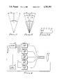
- FIG. 1 is a diagrammatic view showing the lead angle geometry for moving targets
- FIG. 2 is a diagrammatic view of multiple beam geometry for determining the lead angle for a moving target
- FIG. 3 is a diagrammatic view of the beams formed by fiber optics directed at a lens
- FIG. 4 is a block diagram of the encoder and the laser connected to the fiber optics
- FIG. 5 is a block diagram of the encoder
- FIG. 6 is a waveform diagram of encoding signals from the encoder.
- FIG. 7 is a block diagram of the decoding circuit.
- Lead angle correction for a moving target is accomplished in the case of real projectiles by aiming the weapon ahead of the target by an angle which is proportional to the component of target velocity perpendicular to the line of sight to the target and inversely proportional to the component of target velocity perpendicular to the line of sight to the target and inversely proportional to the projectile speed over its path.
- FIG. 1 shows the angular offsets or lead ⁇ 1 and ⁇ 2 required to hit two targets moving with perpendicular velocity components V t1 and V t2 , respectively, when the average projectile speed is Vp.
- electromagnetic beams simulating the projectile path are cause to sequentially point in all of the azimuthal directions, relative to the bore sight of the simulated weapon, that would be necessary to correctly lead any or all of the targets which the simulator is intended to engage.
- This range of angles may be covered sequentially by a single transmitter beam stepped or smoothly scanned over ⁇ s or by N beams individually included to the bore sight direction so as to simultaneously cover the section ⁇ s .
- the number of N of stepped or scanned positions, or of simultaneous individual beams depends upon the width ⁇ b of an individual beam as can be inferred from FIG. 2.
- the beam width ⁇ b depends on the laterial target definition required of the system
- FIGS. 3 and 4 show the utilization of five separate laser diodes 10 connected to a plurality of fiber optic fibers 11 spaced with their output at the focal plane of the lens 12 and spaced in a horizontal line having a spacing 13 which might, for instance, be 0.0045 inches.
- the lenticular shaped lens 12 produces a plurality of beams 14 formed from the radiated energy passing through the optical fibers 11.
- the transmission from each separate beam 14 is assigned a code by the encoder 15 so that the angular space surrounding the weapon in the required vicinity of its bore sight direction is uniquely encoded by simultaneous or sequential electromagnetic radiation.
- a different pulse position code may be assigned to each angular beam position.
- FIG. 6 shows an example of an 8-bit transmit sequence from a PROM memory in the encoder 15 showing a trigger pull signal along with an output code for each of the five lasers 10 along with a master clock signal from the encoder in a pulse position indication.
- the encoder 15 receives its power from a 9 volt battery 16 and is actuated by the trigger switch 17.
- the encoder is more clearly shown in FIG. 5 having the trigger switch 17 connected to a set-reset flip flop 18, which in turn is connected to an 8-stage counter 20, which has the master clock 21 connected thereto.
- the 8-stage counter 20 is connected to a PROM 22 which in turn is connected by lines 23 to each of the five lasers 10.
- the PROM is also connected through a reset line 24 to the set-reset flip flop 18.
- the PROM 22 is actuated by the 8-stage counter 20 which produces an 8-bit transmit sequence as shown in FIG. 6.
- time function fi(t) be members of an orthogonal set without departing from the spirit and scope of the invention.
- the high pulses indicate a high voltage level which causes the laser diode to fire for the length of the sequence of the voltage pulse, emitting from the PROM 22.
- pulse position modulation of five lasers simultaneously is carried out by the use of a master clock 21 that is used as a base frequency for a binary output counter 20, which in turn is used to sequentially address each data location and a PROM 22 that contains the data to be transferred.
- the counter 20 begins clocking at the master clock frequency.
- Each clock pulse causes the output of the counter to increment in a binary fashion such that the output is actually an incremental 8-bit binary word. This 8-bit word incrementally addresses each location in a pre-programmed read only memory 22.
- the PROM 22 outputs 8-bits of data simultaneously, each address selected sequentially addressing the PROM, the eight outputs appear as eight separate serial streams of data, as shown in FIG. 6. Five of these serial data streams are used to activate each of the five lasers 10 in the system. A sixth output is used in the transmit sequence, while the remaining outputs are not used.
- the PROM allows recognizable pulse positioning modulated data to be output so that each data bit that is output requires meaning from its position and time with respect to the master clock frequency.
- Data transferred in this matter has a predefined message length, as shown in FIG. 6.
- the message length as shown in the timing diagram is eight master clock periods long with an 8-bit transmit message and a total of 128 different messages can be sent from all data positions being low to all data positions being high.
- the pre-programmed reset line 24 goes to a high voltage level and resets the counter.
- the counter stays in the reset condition, which outputs a binary count of zero until the next trigger pull occurs. All outputs from the PROM 22 are low at this address, and therefore, no laser transmissions occur. Whenever a trigger pull is actuated, the counter 20 is allowed to clock and the sequence begins again.
- the target is equipped with a detector or detectors of the electromagnetic radiation transmitted by the direct fire weapon simulator.
- the electromagnetic radiation detector is followed by a decoder which is designed to recognize which of the unique time functions of f i (t) transmitted by the weapon simulator has illuminated the target.
- the target receiver has determined the angular position of the weapon bore sight relative to the weapon target line of sight at the time of fire. The angle so determined is the azimuth lead angle.
- the target scalar speed is ordinarily limited to only one, or at most a few, values and the target moves from left to right or from right to left along a fixed track.
- the orientation of the fixed track relative to the gunner's firing position is also know as is the type of ammunition and hence the average projectile velocity being simulated.
- the possible velocities of the target perpendicular to the line of sight are easily determined for all target scalar speeds and directions of motion is either provided by electrical or mechanical signals from the moving target platforms. When the target is set in motion, therefore, sufficient information is available to specify the lead angle which the gunner must take to hit it. Knowing the relationship by means of which the off bore sight
- beam angle ⁇ 1 is encoded onto the weapon simulator's transmitted time function f i (t), the receiver/decoder can determine what time function it must receive in order to be "hit”. This determination can be done by direct computation, by a look-up table, or by other means.
- the decoder logic must take into account the "sense" of the time function that must be received in order to be scored as a proper lead, recognizing that if the weapon is required to lead the target by ⁇ i , the proper time function is that belonging to an off-bore sight angle of ⁇ i .
- the laser pulse from the lasers 10 activates an optical detector target 25 attached to a movable target (not shown) and feeds the received laser pulses to a synchronization circuit 26.
- the optical detector 25 produces a voltage pulse each time a laser pulse is sensed.
- These pulses are synchronized in the circuit 26 to the decoder master clock 27 so that the pulse train information can be identified directly with respect to its position and time as compared to the master clock time period.
- the data pulses are clocked into an 8-bit shift register.
- the 8-bit shift register converts serial pulse position modulated data into a parallel simultaneously occurring 8-bit binary word.
- the binary word is used to address a pre-programmed PROM memory 30 and address locations whose binary representation is equal to the 8-bit code of each of the five lasers 10 transmission codes produced by the encoder 15.
- One of the five used output lines 31 is programmed to produce an output. Whenever the address from the shift register 28 is the same as one of the five laser transmission codes produced by the encoder, the particular output from the PROM that goes high indicates which of the five different laser messages has been received.
- a method of determining the correct lead for a moving target on a laser weapon simulator system includes the steps of encoding a plurality of adjacent laser beams fired along a weapon bore sight, directing the laser beams towards a target having a laser beam detector thereon and decoding the encoded laser beams to determine the lead of the laser weapon simulator.
- a weapon simulator has been provided which enables a gunner to correctly lead a moving target when using a laser direct fire weapon simulator for markmanship training. It should, however, also be clear that it is anticipated that the simulator will be attached directly to a gunner's weapon and that the optical detector and decoder can be attached directly to existing training targets.
- the optical receivers can be of any different type, such as shown in U.S. Pat. No. 4,299,393 for an AREA RADIATION TARGET. It will also be clear that the blocks in the block diagram are all conventional circuit elements.
Abstract
Description
Claims (8)
Priority Applications (1)
| Application Number | Priority Date | Filing Date | Title |
|---|---|---|---|
| US06/387,933 US4781593A (en) | 1982-06-14 | 1982-06-14 | Lead angle correction for weapon simulator apparatus and method |
Applications Claiming Priority (1)
| Application Number | Priority Date | Filing Date | Title |
|---|---|---|---|
| US06/387,933 US4781593A (en) | 1982-06-14 | 1982-06-14 | Lead angle correction for weapon simulator apparatus and method |
Publications (1)
| Publication Number | Publication Date |
|---|---|
| US4781593A true US4781593A (en) | 1988-11-01 |
Family
ID=23531915
Family Applications (1)
| Application Number | Title | Priority Date | Filing Date |
|---|---|---|---|
| US06/387,933 Expired - Lifetime US4781593A (en) | 1982-06-14 | 1982-06-14 | Lead angle correction for weapon simulator apparatus and method |
Country Status (1)
| Country | Link |
|---|---|
| US (1) | US4781593A (en) |
Cited By (16)
| Publication number | Priority date | Publication date | Assignee | Title |
|---|---|---|---|---|
| EP0379474A1 (en) * | 1989-01-17 | 1990-07-25 | S.A. Leentjens-Boes | Apparatus for use with fire simulation and weapon training systems |
| EP0384913A1 (en) * | 1989-02-21 | 1990-08-29 | S.A. Leentjens-Boes | Guiding circuit for making use of simulation and shooting practice systems |
| US5083034A (en) * | 1990-02-12 | 1992-01-21 | Hughes Aircraft Company | Multi-wavelength target system |
| WO1995000813A1 (en) * | 1993-06-25 | 1995-01-05 | The Commonwealth Of Australia | Maw flight line test set |
| US5741185A (en) * | 1997-02-05 | 1998-04-21 | Toymax Inc. | Interactive light-operated toy shooting game |
| US5904621A (en) * | 1997-06-25 | 1999-05-18 | Tiger Electronics, Ltd. | Electronic game with infrared emitter and sensor |
| US5984788A (en) * | 1997-06-09 | 1999-11-16 | Toymax Inc. | Interactive toy shooting game having a target with a feelable output |
| US6139323A (en) * | 1997-07-10 | 2000-10-31 | C.O.E.L. Entwicklungsgesellschaft Mbh | Weapon effect simulation method and appliance to perform this method |
| US6302796B1 (en) | 1997-02-05 | 2001-10-16 | Toymax Inc. | Player programmable, interactive toy for a shooting game |
| US20030157463A1 (en) * | 2002-02-15 | 2003-08-21 | Nec Corporation | Shooting training system with device allowing instructor to exhibit example to player in real-time |
| US20040033472A1 (en) * | 2002-08-14 | 2004-02-19 | Deepak Varshneya | All-optical precision gunnery simulation (PGS) method and system |
| US20060287113A1 (en) * | 2005-05-19 | 2006-12-21 | Small David B | Lazer tag advanced |
| US20060287114A1 (en) * | 2005-06-03 | 2006-12-21 | Binh Luong | Electronic tag game |
| WO2006134202A1 (en) * | 2005-06-17 | 2006-12-21 | Iprbox Oy | Laser System and Method |
| US20080188314A1 (en) * | 2007-01-04 | 2008-08-07 | Brian Rosenblum | Toy laser gun and laser target system |
| US20100261145A1 (en) * | 2005-06-22 | 2010-10-14 | Saab Ab | A system and a method for transmission of information |
Citations (4)
| Publication number | Priority date | Publication date | Assignee | Title |
|---|---|---|---|---|
| US4063368A (en) * | 1976-08-16 | 1977-12-20 | Manned Systems Sciences, Inc. | Laser weapons simulation system |
| US4218138A (en) * | 1978-03-02 | 1980-08-19 | Saab-Scania Aktiebolag | Method and means for determining positions of reflectors with fan-shaped beams |
| US4218834A (en) * | 1978-03-02 | 1980-08-26 | Saab-Scania Ab | Scoring of simulated weapons fire with sweeping fan-shaped beams |
| US4229103A (en) * | 1978-01-20 | 1980-10-21 | Jan Hipp | Apparatus for determining off-aim during firing simulation |
-
1982
- 1982-06-14 US US06/387,933 patent/US4781593A/en not_active Expired - Lifetime
Patent Citations (4)
| Publication number | Priority date | Publication date | Assignee | Title |
|---|---|---|---|---|
| US4063368A (en) * | 1976-08-16 | 1977-12-20 | Manned Systems Sciences, Inc. | Laser weapons simulation system |
| US4229103A (en) * | 1978-01-20 | 1980-10-21 | Jan Hipp | Apparatus for determining off-aim during firing simulation |
| US4218138A (en) * | 1978-03-02 | 1980-08-19 | Saab-Scania Aktiebolag | Method and means for determining positions of reflectors with fan-shaped beams |
| US4218834A (en) * | 1978-03-02 | 1980-08-26 | Saab-Scania Ab | Scoring of simulated weapons fire with sweeping fan-shaped beams |
Cited By (22)
| Publication number | Priority date | Publication date | Assignee | Title |
|---|---|---|---|---|
| EP0379474A1 (en) * | 1989-01-17 | 1990-07-25 | S.A. Leentjens-Boes | Apparatus for use with fire simulation and weapon training systems |
| BE1002748A3 (en) * | 1989-01-17 | 1991-05-28 | Leentjens Boes Sa | APPARATUS FOR THE USE OF SIMULATION AND SHOOTING TRAINING SYSTEMS. |
| EP0384913A1 (en) * | 1989-02-21 | 1990-08-29 | S.A. Leentjens-Boes | Guiding circuit for making use of simulation and shooting practice systems |
| BE1002846A3 (en) * | 1989-02-21 | 1991-07-02 | Leentjens Boes Sa | DRIVING CIRCUIT FOR THE USE OF SIMULATION AND SHOOTING TRAINING SYSTEMS. |
| US5083034A (en) * | 1990-02-12 | 1992-01-21 | Hughes Aircraft Company | Multi-wavelength target system |
| WO1995000813A1 (en) * | 1993-06-25 | 1995-01-05 | The Commonwealth Of Australia | Maw flight line test set |
| US6302796B1 (en) | 1997-02-05 | 2001-10-16 | Toymax Inc. | Player programmable, interactive toy for a shooting game |
| US5741185A (en) * | 1997-02-05 | 1998-04-21 | Toymax Inc. | Interactive light-operated toy shooting game |
| US5984788A (en) * | 1997-06-09 | 1999-11-16 | Toymax Inc. | Interactive toy shooting game having a target with a feelable output |
| US5904621A (en) * | 1997-06-25 | 1999-05-18 | Tiger Electronics, Ltd. | Electronic game with infrared emitter and sensor |
| US6139323A (en) * | 1997-07-10 | 2000-10-31 | C.O.E.L. Entwicklungsgesellschaft Mbh | Weapon effect simulation method and appliance to perform this method |
| SG121758A1 (en) * | 2002-02-15 | 2006-05-26 | Nec Corp | Shooting training system with device allowing instructor to exhibit example to player in real-time |
| US20030157463A1 (en) * | 2002-02-15 | 2003-08-21 | Nec Corporation | Shooting training system with device allowing instructor to exhibit example to player in real-time |
| US20040033472A1 (en) * | 2002-08-14 | 2004-02-19 | Deepak Varshneya | All-optical precision gunnery simulation (PGS) method and system |
| US20060287113A1 (en) * | 2005-05-19 | 2006-12-21 | Small David B | Lazer tag advanced |
| US7846028B2 (en) | 2005-05-19 | 2010-12-07 | Shoot The Moon Products Ii, Llc | Lazer tag advanced |
| US20060287114A1 (en) * | 2005-06-03 | 2006-12-21 | Binh Luong | Electronic tag game |
| WO2006134202A1 (en) * | 2005-06-17 | 2006-12-21 | Iprbox Oy | Laser System and Method |
| US20100261145A1 (en) * | 2005-06-22 | 2010-10-14 | Saab Ab | A system and a method for transmission of information |
| US7844183B2 (en) * | 2005-06-22 | 2010-11-30 | Saab Ab | System and a method for transmission of information |
| US20080188314A1 (en) * | 2007-01-04 | 2008-08-07 | Brian Rosenblum | Toy laser gun and laser target system |
| US8721460B2 (en) | 2007-01-04 | 2014-05-13 | Jakks Pacific, Inc. | Toy laser gun and laser target system |
Similar Documents
| Publication | Publication Date | Title |
|---|---|---|
| US4781593A (en) | Lead angle correction for weapon simulator apparatus and method | |
| US4592554A (en) | Equipment for simulated shooting | |
| US4229103A (en) | Apparatus for determining off-aim during firing simulation | |
| US3832791A (en) | Gunnery training scoring system with laser pulses | |
| US4478581A (en) | Method and apparatus for shooting simulation of ballistic ammunition _with movable targets | |
| US3955292A (en) | Apparatus for antiaircraft gunnery practice with laser emissions | |
| US3588108A (en) | Weapon-training systems | |
| CA1116278A (en) | Method and means for transmission of information by sweeping fan-shaped beams | |
| US4577962A (en) | Method and equipment for the control of aiming and firing at a real target | |
| US4232456A (en) | Weapons system simulator and method including ranging system | |
| US3927480A (en) | Gunnery training scoring system with laser pulses | |
| US4629427A (en) | Laser operated small arms transmitter with near field reflection inhibit | |
| HUP0303748A2 (en) | Method and device for simulating firing | |
| GB2037957A (en) | Shot simulators using laser light for simulating shooting of light guided missiles | |
| US4234141A (en) | Range gated retroreflective missile guidance system | |
| GB2171501A (en) | Practising the aiming of a firearm | |
| US6817569B1 (en) | Guidance seeker system with optically triggered diverter elements | |
| US4959016A (en) | Weapon training systems | |
| FI894294A0 (en) | Method and sieving device for groove alignment of fire control and weapon devices | |
| US3807658A (en) | Rate transmittal method for beamrider missile guidance | |
| EP1737146B1 (en) | A system and a method for transmission of information | |
| US4432511A (en) | Beam-rider guidance using two overlapping reticle discs | |
| EP3545254B1 (en) | A simulation device and a method for facilitating simulation of a shot from a weapon | |
| GB2147693A (en) | Area weapon simulator | |
| EP1196733B1 (en) | Ring array projectile steering with optically-triggered diverter elements |
Legal Events
| Date | Code | Title | Description |
|---|---|---|---|
| AS | Assignment |
Owner name: INTERNATIONAL LASER SYSTEMS, INC. 3404 NORTH ORANG Free format text: ASSIGNMENT OF ASSIGNORS INTEREST.;ASSIGNORS:BIRGE, WARREN A.;WANGLER, RICHARD J.;REEL/FRAME:004022/0493 Effective date: 19820614 Owner name: INTERNATIONAL LASER SYSTEMS, INC., A CORP. OF, FLO Free format text: ASSIGNMENT OF ASSIGNORS INTEREST;ASSIGNORS:BIRGE, WARREN A.;WANGLER, RICHARD J.;REEL/FRAME:004022/0493 Effective date: 19820614 |
|
| STCF | Information on status: patent grant |
Free format text: PATENTED CASE |
|
| FEPP | Fee payment procedure |
Free format text: PAYOR NUMBER ASSIGNED (ORIGINAL EVENT CODE: ASPN); ENTITY STATUS OF PATENT OWNER: LARGE ENTITY |
|
| FPAY | Fee payment |
Year of fee payment: 4 |
|
| FPAY | Fee payment |
Year of fee payment: 8 |
|
| FPAY | Fee payment |
Year of fee payment: 12 |