US4781040A - Latch needle for knitting machine - Google Patents

Latch needle for knitting machine Download PDF

Info

Publication number
US4781040A
US4781040A US07/069,738 US6973887A US4781040A US 4781040 A US4781040 A US 4781040A US 6973887 A US6973887 A US 6973887A US 4781040 A US4781040 A US 4781040A
Authority
US
United States
Prior art keywords
latch
pivots
side walls
hook
slanted
Prior art date
Legal status (The legal status is an assumption and is not a legal conclusion. Google has not performed a legal analysis and makes no representation as to the accuracy of the status listed.)
Expired - Fee Related
Application number
US07/069,738
Inventor
Fuji Koike
Current Assignee (The listed assignees may be inaccurate. Google has not performed a legal analysis and makes no representation or warranty as to the accuracy of the list.)
LOYAL KOGYO KK
Original Assignee
LOYAL KOGYO KK
Priority date (The priority date is an assumption and is not a legal conclusion. Google has not performed a legal analysis and makes no representation as to the accuracy of the date listed.)
Filing date
Publication date
Priority claimed from JP10351086U external-priority patent/JPS6314593U/ja
Priority claimed from JP14102686U external-priority patent/JPS6346491U/ja
Priority claimed from JP14102786U external-priority patent/JPS6346492U/ja
Application filed by LOYAL KOGYO KK filed Critical LOYAL KOGYO KK
Assigned to LOYAL KOGYO KABUSHIKI KAISHA reassignment LOYAL KOGYO KABUSHIKI KAISHA ASSIGNMENT OF ASSIGNORS INTEREST. Assignors: KOIKE, FUJI
Application granted granted Critical
Publication of US4781040A publication Critical patent/US4781040A/en
Anticipated expiration legal-status Critical
Expired - Fee Related legal-status Critical Current

Links

Images

Classifications

    • DTEXTILES; PAPER
    • D04BRAIDING; LACE-MAKING; KNITTING; TRIMMINGS; NON-WOVEN FABRICS
    • D04BKNITTING
    • D04B35/00Details of, or auxiliary devices incorporated in, knitting machines, not otherwise provided for
    • D04B35/02Knitting tools or instruments not provided for in group D04B15/00 or D04B27/00
    • D04B35/04Latch needles

Definitions

  • the invention relates generally to a latch needle for a knitting machine, and more particularly to the knitting needle to be assembled from an extended needle body and a latch respectively plastically formed from a synthetic resin.
  • the needle comprises an extended needle body consisting of a shank portion, a hook portion formed at one end thereof and a butt portion at the other end, as well as a latch pivotably mounted in a slot formed in said shank portion at the root of said hook so as to angularly move by an angle of about 165°-170° alternately between a hook open position and a hook closed position.
  • the invention does not lie in the improvements of such nature but intends ready assembly of the latch needle and consequently provide inexpensive latch needles.
  • latch needles have been made of a metallic material such as stainless steel, but recently such knitting needles have been made of synthetic resin.
  • a thermoplastic resin of high mechanical strength and some flexibility, among which polyacetal, seems to be most preferable also in view of the moderate cost are marketed.
  • the inventor has not found any printed material to be named here as to such a latch needle.
  • the latch having a pair of transversely protruded pivots arranged at the root portion thereof is plastically formed from said synthetic resin.
  • the extended needle body having the slot defined by a pair of cheek walls, each having a hole for engaging with said pivot is plastically formed from the synthetic resin.
  • the width of the latch is slightly smaller than that of said the slot, but the latch integrally formed with oppositely protruded pivots cannot be brought in engagement with said holes formed in the side walls.
  • the slot width must be spreaded with using a wedge tool and when the latch pivots are fitted in the holes, the tool is withdrawn so that opposite cheek walls are brought into the initial positions owing to the flexibility of the material.
  • Such manual assembly is, however, not so easy particularly when the needle is of fine gauge and thus the slot width is thin.
  • An object of the invention is, thus to provide a latch needle for knitting machines to be readily assembled from an extended needle body and a latch respectively plastically formed from a synthetic resin without any necessity of a particular tool.
  • FIG. 1 is a side elevation of the typical latch needle and also the needle of the invention
  • FIG. 2 is a similar view in an enlarged scale of the latch and a part of the elongated needle body before assembly
  • FIG. 3 is a top plan view of a part of said needle body
  • FIG. 4 is also a top plan view but of the latch according to the invention.
  • FIG. 5 is a transverse sectional view taken along a line V--V in FIG. 4 and of the concerned portion of the needle body
  • FIG. 6 is a top plan view of the latch according to the second embodiment of the invention.
  • FIG. 7 is a transverse sectional view similar to FIG. 5 but for illustrating said second embodiment
  • FIG. 8 is a top plan view similar to FIG. 3 but illustrating the third embodiment of the invention.
  • FIG. 9 is a transverse sectional view similar to FIG. 7 but for illustrating said third embodiment.
  • an extended needle body represented generally by 10 has a hook portion 11, a butt portion 12 and a shank portion 13 integrally connecting the two portions.
  • a latch represented generally by 20 has a latch spoon 21 at one end thereof and a pair of transversely protruded pivots 22 at the other end.
  • the slot 14 is defined by a pair of cheek walls 15 (FIG. 3) and slanted bottom walls 16.
  • the cheek walls 15, 15 are respectively formed with holes 17 so as to be fitted with the protruded pivots 22 for angular movement of the latch 20 relative to the needle body 10 by an angle of about 165°-170° which is defined by the inclination of said slanted bottom walls 16, 16.
  • the width of the latch 20 is slightly smaller than that of the slot 14 and the diameter of the pivot 22 is slightly smaller than that of the hole 17 for ensuring smooth angular movement and for preventing the pivot 22 from disengaging out of the hole 17. It is preferable for the cheek wall 15 to be formed in a hill of which top lies above the hole 17.
  • the slot 14 is partly open in general at the bottom thereof.
  • the latch 20 is angularly moved alternately during the knitting operation, as well known to those skilled in the art, between the position illustrated by solid lines in FIG. 1 where the latch 20 lies on the slanted bottom wall 16 near the hook 11 and the latch spoon 21 rests on the free end of the hook to be closed and the opposite position illustrated by phantom lines where the latch 20 lies on the other slanted bottom wall 16 so as to open the hook, by the angle degree referred to above.
  • each of the protruded pivots 22 has a slanted face 23 at the lower half of the so that the axial length of the pivot is made zero or the width of the latch inclusive of the opposite pivots is made substantially same with the latch itself at the lower end of said slanted face 23.
  • the opposite cheek walls 15, 15 are resiliently spreaded with the portion where the holes 17, 17 are formed as the central points by virtue of the wedge action by said slanted face 23 so that the pivots 22, may be fitted in the holes 17, as best shown in FIG. 5.
  • each of the rounded ridge lines 23',23' is to be decided depending on the flexibility of the material of the cheek wall, the thickness thereof, the length of the protruded pivot and so on for realizing the desirable spread of the slot width.
  • each of the pivots 22 is formed to be substantially hemispherical. There will be no need for further explanation on the assembly.
  • cheek walls 15, in the first and third embodiments may also have slanted surfaces along the ridge line like as in the second embodiment in FIG. 7.

Abstract

Disclosed is a latch needle for knitting machine to be readily assembled from a latch having a pair of transversely protruded pivots and plastically formed from a synthetic resin, as well as an extended needle body consisting of a shank portion. A hook portion is formed at one end thereof and a butt portion at the other end, in which said shank portion has a slot defined by opposite side walls, each having a hole for engagement with each of said pivots. A pair of slanted bottom walls receive said latch for angular movement, which is also plastically formed from the synthetic resin. Owing to slanted face formed on said pivots or said side walls, the latch may be pushed or stricken down in the slot with resiliently spreading the side walls.

Description

BACKGROUND OF THE INVENTION
The invention relates generally to a latch needle for a knitting machine, and more particularly to the knitting needle to be assembled from an extended needle body and a latch respectively plastically formed from a synthetic resin.
There have been proposed and actually used various latch needles for knitting, but it is generally common to all of them that the needle comprises an extended needle body consisting of a shank portion, a hook portion formed at one end thereof and a butt portion at the other end, as well as a latch pivotably mounted in a slot formed in said shank portion at the root of said hook so as to angularly move by an angle of about 165°-170° alternately between a hook open position and a hook closed position.
In order to solve various problems or troubles caused by such alternate angular movement of the latch, for instance in order to lessen damage to the free end of the latch which is often called the latch spoon and to the side walls defining the slot, some proposals have been made as seen in e.g. U.S. Pat. Nos. 4,294,086 and 4,512,164. In order to assure that the latch will not come to rest beside or underneath the needle head when closing the hook, which is inevitably caused from the lateral mobility of the latch, U.S. Pat. No. 4,498,315 has proposed a countermeasure.
The invention does not lie in the improvements of such nature but intends ready assembly of the latch needle and consequently provide inexpensive latch needles.
In the past the latch needles have been made of a metallic material such as stainless steel, but recently such knitting needles have been made of synthetic resin. A thermoplastic resin of high mechanical strength and some flexibility, among which polyacetal, seems to be most preferable also in view of the moderate cost are marketed. The inventor has not found any printed material to be named here as to such a latch needle.
The latch having a pair of transversely protruded pivots arranged at the root portion thereof is plastically formed from said synthetic resin. Separately therefrom the extended needle body having the slot defined by a pair of cheek walls, each having a hole for engaging with said pivot is plastically formed from the synthetic resin. The width of the latch is slightly smaller than that of said the slot, but the latch integrally formed with oppositely protruded pivots cannot be brought in engagement with said holes formed in the side walls. In assembly the slot width must be spreaded with using a wedge tool and when the latch pivots are fitted in the holes, the tool is withdrawn so that opposite cheek walls are brought into the initial positions owing to the flexibility of the material. Such manual assembly is, however, not so easy particularly when the needle is of fine gauge and thus the slot width is thin.
SUMMARY OF THE INVENTION
An object of the invention is, thus to provide a latch needle for knitting machines to be readily assembled from an extended needle body and a latch respectively plastically formed from a synthetic resin without any necessity of a particular tool.
Other objects and various advantages of the invention will be appreciated by reading the following explanation in more detail to be made hereafter in reference to the accompanying drawings.
BRIEF DESCRIPTION OF THE DRAWINGS
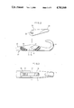
FIG. 1 is a side elevation of the typical latch needle and also the needle of the invention,
FIG. 2 is a similar view in an enlarged scale of the latch and a part of the elongated needle body before assembly,
FIG. 3 is a top plan view of a part of said needle body,
FIG. 4 is also a top plan view but of the latch according to the invention,
FIG. 5 is a transverse sectional view taken along a line V--V in FIG. 4 and of the concerned portion of the needle body,
FIG. 6 is a top plan view of the latch according to the second embodiment of the invention,
FIG. 7 is a transverse sectional view similar to FIG. 5 but for illustrating said second embodiment,
FIG. 8 is a top plan view similar to FIG. 3 but illustrating the third embodiment of the invention, and
FIG. 9 is a transverse sectional view similar to FIG. 7 but for illustrating said third embodiment.
DESCRIPTION OF THE PREFERRED EMBODIMENTS
With reference to FIG. 1, 2 and 3, an extended needle body represented generally by 10 has a hook portion 11, a butt portion 12 and a shank portion 13 integrally connecting the two portions. A latch represented generally by 20 has a latch spoon 21 at one end thereof and a pair of transversely protruded pivots 22 at the other end.
As best shown in FIG. 2, there is formed a slot 14 in the needle shank 13 in the vicinity of the hook 11. The slot 14 is defined by a pair of cheek walls 15 (FIG. 3) and slanted bottom walls 16. The cheek walls 15, 15 are respectively formed with holes 17 so as to be fitted with the protruded pivots 22 for angular movement of the latch 20 relative to the needle body 10 by an angle of about 165°-170° which is defined by the inclination of said slanted bottom walls 16, 16.
The width of the latch 20 is slightly smaller than that of the slot 14 and the diameter of the pivot 22 is slightly smaller than that of the hole 17 for ensuring smooth angular movement and for preventing the pivot 22 from disengaging out of the hole 17. It is preferable for the cheek wall 15 to be formed in a hill of which top lies above the hole 17. The slot 14 is partly open in general at the bottom thereof.
The latch 20 is angularly moved alternately during the knitting operation, as well known to those skilled in the art, between the position illustrated by solid lines in FIG. 1 where the latch 20 lies on the slanted bottom wall 16 near the hook 11 and the latch spoon 21 rests on the free end of the hook to be closed and the opposite position illustrated by phantom lines where the latch 20 lies on the other slanted bottom wall 16 so as to open the hook, by the angle degree referred to above.
The construction and arrangement themselves explained in the above description have no direct connection with the invention which is characterized in configuration of the pivot and/or concerned portion of the cheek walls particularly formed for the purpose of making the assembly easy.
Now with reference to FIGS. 4, and 5, each of the protruded pivots 22 has a slanted face 23 at the lower half of the so that the axial length of the pivot is made zero or the width of the latch inclusive of the opposite pivots is made substantially same with the latch itself at the lower end of said slanted face 23. Owing to such configuration of the pivots 22, when the latch 20 is inserted in the slot 14 only with the bottom portion thereof and then pushed or struck down in the direction vertical to the axis of the latch laid along the slanted bottom wall 16 close to the hook 11 and consequently vertical to the surface of said slanted bottom wall (see also FIGS. 1 and 2), the opposite cheek walls 15, 15 are resiliently spreaded with the portion where the holes 17, 17 are formed as the central points by virtue of the wedge action by said slanted face 23 so that the pivots 22, may be fitted in the holes 17, as best shown in FIG. 5.
In reference to FIGS. 6 and 7, the pivots 22, themselves are usual but slanted faces 23' , 23' are formed at the opposite ridge lines where the inner surfaces and the upper surfaces of the opposite cheek walls 15, 15 are respectively crossed. The longitudinal extension of each of the rounded ridge lines 23',23' is to be decided depending on the flexibility of the material of the cheek wall, the thickness thereof, the length of the protruded pivot and so on for realizing the desirable spread of the slot width.
Finally in reference to FIGS. 8 and 9 each of the pivots 22 is formed to be substantially hemispherical. There will be no need for further explanation on the assembly.
Although there is no particular illustration in the drawings, there may be formed a shallow guide grooves in the inner surface of the cheek wall 15 so that the free end of the pivot 22 may be urgingly moved therealong down to reach the hole 17. Various modifications may be made on the illustrated embodiments by those skilled in the art as occasion demands. For instance, the cheek walls 15, in the first and third embodiments may also have slanted surfaces along the ridge line like as in the second embodiment in FIG. 7.

Claims (6)

What is claimed is:
1. Latch needle for knitting machines comprising an extended needle body plastically formed from a synthetic resin and consisting of a shank portion, a hook portion formed at one end thereof and a butt portion at the other end, said shank portion having a slot formed in the vicinity of said hook portion and defined by a pair of side walls, each having a hole, and a pair of oppositely slanted bottom walls; and a latch plastically formed from the synthetic resin and having a latch spoon at one end thereof and a pair of transversely protruded opposite pivots at the other end so that when said pivots are fitted in said holes the latch may be angularly moved alternately between the closed position where said latch lies on one of said slanted bottom wall near to the hook with the latch spoon resting on the free end of the hook and the open position where said latch lies on the other slanted bottom wall remote from the hook by an angle a little smaller than 180° which is defined by the inclination of said slanted bottom walls, in which rounded faces are formed on either of the pivots and the concerned portion of the side walls so that when the latch partly inserted in said slot is urged to move down the side walls are resiliently spreaded owing to wedge action to be caused by said rounded faces so that said pivots may engage with said holes and then the side walls may be brought into the initial positions by virtue of the flexibility of the synthetic resin.
2. Latch needle according to claim 1, in which each of said pivots is formed with a slanted face at the lower half of the free end thereof so that the axial length of the pivot is made zero at the lower end of said slanted face.
3. Latch needle according to claim 1, in which each of said side walls is formed with a rounded face along a ridge line where the inner surface and the upper surface of said side wall are crossed.
4. Latch needle according to claim 1, in which each of said pivots is formed to be substantially hemispherical.
5. Latch needle according to claim 2, in which each of the side walls is formed with a rounded face along a ridge line where the inner and upper surfaces of said side wall are crossed.
6. Latch needle according to claim 4, in which each of the side walls is formed with a rounded face along a ridge line where the inner and upper surfaces of said side wall are crossed.
US07/069,738 1986-07-04 1987-07-06 Latch needle for knitting machine Expired - Fee Related US4781040A (en)

Applications Claiming Priority (5)

Application Number Priority Date Filing Date Title
JP10351086U JPS6314593U (en) 1986-07-04 1986-07-04
JP61-103510[U] 1986-07-04
JP14102686U JPS6346491U (en) 1986-09-16 1986-09-16
JP61-141026[U]JPX 1986-09-16
JP14102786U JPS6346492U (en) 1986-09-16 1986-09-16

Publications (1)

Publication Number Publication Date
US4781040A true US4781040A (en) 1988-11-01

Family

ID=27310008

Family Applications (1)

Application Number Title Priority Date Filing Date
US07/069,738 Expired - Fee Related US4781040A (en) 1986-07-04 1987-07-06 Latch needle for knitting machine

Country Status (1)

Country Link
US (1) US4781040A (en)

Cited By (4)

* Cited by examiner, † Cited by third party
Publication number Priority date Publication date Assignee Title
US4817398A (en) * 1987-05-07 1989-04-04 Theodor Groz & Sohne & Ernst Beckert Nadelfabrik Commandit-Gesellschaft Latch needle for loop forming textile machines
US4905364A (en) * 1988-01-14 1990-03-06 Theodor Groz & Sohne & Ernst Beckert Nadelfabrik Commandit-Gesellschaft Method for producing the latch bearing in a latch needle for textile machines
US20100164631A1 (en) * 2008-12-31 2010-07-01 Cirrus Logic, Inc. Electronic system having common mode voltage range enhancement
US20100212366A1 (en) * 2009-02-26 2010-08-26 Groz-Beckert Kg Latch Needle with Rotating Swivel Pin

Citations (6)

* Cited by examiner, † Cited by third party
Publication number Priority date Publication date Assignee Title
US2711218A (en) * 1950-09-21 1955-06-21 Vitoux Marcel Method of mounting pivoted latches on self-acting needles for knitting and relooping machines
DE1026914B (en) * 1956-03-03 1958-03-27 Alfred Schubert Latch needle or double latch needle, especially for circular and flat knitting machines
FR1271113A (en) * 1960-07-25 1961-09-08 Le Lit Tous Soins Improvements to medical beds
US3453845A (en) * 1966-11-08 1969-07-08 Redditch Hosiery Needles Ltd Latched needles
US3459009A (en) * 1966-06-21 1969-08-05 Groz & Soehne Theodor Latch needle for knitting machines
US4548056A (en) * 1981-08-22 1985-10-22 Theodor Groz & Sohne & Ernst Beckert Stamped knitting tool for knitting machines

Patent Citations (6)

* Cited by examiner, † Cited by third party
Publication number Priority date Publication date Assignee Title
US2711218A (en) * 1950-09-21 1955-06-21 Vitoux Marcel Method of mounting pivoted latches on self-acting needles for knitting and relooping machines
DE1026914B (en) * 1956-03-03 1958-03-27 Alfred Schubert Latch needle or double latch needle, especially for circular and flat knitting machines
FR1271113A (en) * 1960-07-25 1961-09-08 Le Lit Tous Soins Improvements to medical beds
US3459009A (en) * 1966-06-21 1969-08-05 Groz & Soehne Theodor Latch needle for knitting machines
US3453845A (en) * 1966-11-08 1969-07-08 Redditch Hosiery Needles Ltd Latched needles
US4548056A (en) * 1981-08-22 1985-10-22 Theodor Groz & Sohne & Ernst Beckert Stamped knitting tool for knitting machines

Cited By (5)

* Cited by examiner, † Cited by third party
Publication number Priority date Publication date Assignee Title
US4817398A (en) * 1987-05-07 1989-04-04 Theodor Groz & Sohne & Ernst Beckert Nadelfabrik Commandit-Gesellschaft Latch needle for loop forming textile machines
US4905364A (en) * 1988-01-14 1990-03-06 Theodor Groz & Sohne & Ernst Beckert Nadelfabrik Commandit-Gesellschaft Method for producing the latch bearing in a latch needle for textile machines
US20100164631A1 (en) * 2008-12-31 2010-07-01 Cirrus Logic, Inc. Electronic system having common mode voltage range enhancement
US20100212366A1 (en) * 2009-02-26 2010-08-26 Groz-Beckert Kg Latch Needle with Rotating Swivel Pin
US7913519B2 (en) * 2009-02-26 2011-03-29 Groz-Beckert Kg Latch needle with rotating swivel pin

Similar Documents

Publication Publication Date Title
USD298698S (en) Knitting needle
US4781040A (en) Latch needle for knitting machine
US5093966A (en) Pull tab assembly for slide fastener slider
NZ233567A (en) Wire nail with penetrating, wedging and transitional portions
JPS6332905B2 (en)
JPS61183994U (en)
US4548056A (en) Stamped knitting tool for knitting machines
JPH0737701B2 (en) Tools for knitting machine
CA2172770C (en) Latch needle for knitting machines
US4723425A (en) Latch needle for textile machine
JPS6226468Y2 (en)
WO2006070840A1 (en) Movable sinker and weft knitting machine equipped with movable sinker
KR840000047B1 (en) Double nail
US3430637A (en) Pin curl clip
JPS6452457U (en)
US6564589B2 (en) Latch needle having a stepped saw slot
JPS6190892U (en)
JPS61168190U (en)
US2429210A (en) Knitting machine needle
JPS6267781U (en)
JPS60127387U (en) stockinette knitting needles
JPS62148590U (en)
JPS5983994U (en) stockinette knitting needles
JPH0278409U (en)
JPH0294015U (en)

Legal Events

Date Code Title Description
AS Assignment

Owner name: LOYAL KOGYO KABUSHIKI KAISHA, 28, TOYOSHIRO-CHO 3-

Free format text: ASSIGNMENT OF ASSIGNORS INTEREST.;ASSIGNOR:KOIKE, FUJI;REEL/FRAME:004910/0219

Effective date: 19870617

Owner name: LOYAL KOGYO KABUSHIKI KAISHA,JAPAN

Free format text: ASSIGNMENT OF ASSIGNORS INTEREST;ASSIGNOR:KOIKE, FUJI;REEL/FRAME:004910/0219

Effective date: 19870617

REMI Maintenance fee reminder mailed
LAPS Lapse for failure to pay maintenance fees
FP Lapsed due to failure to pay maintenance fee

Effective date: 19921101

STCH Information on status: patent discontinuation

Free format text: PATENT EXPIRED DUE TO NONPAYMENT OF MAINTENANCE FEES UNDER 37 CFR 1.362