US4771780A - Rate-responsive pacemaker having digital motion sensor - Google Patents
Rate-responsive pacemaker having digital motion sensor Download PDFInfo
- Publication number
- US4771780A US4771780A US07/003,433 US343387A US4771780A US 4771780 A US4771780 A US 4771780A US 343387 A US343387 A US 343387A US 4771780 A US4771780 A US 4771780A
- Authority
- US
- United States
- Prior art keywords
- pacemaker
- conductive element
- housing
- electrodes
- motion
- Prior art date
- Legal status (The legal status is an assumption and is not a legal conclusion. Google has not performed a legal analysis and makes no representation as to the accuracy of the status listed.)
- Expired - Lifetime
Links
Images
Classifications
-
- A—HUMAN NECESSITIES
- A61—MEDICAL OR VETERINARY SCIENCE; HYGIENE
- A61N—ELECTROTHERAPY; MAGNETOTHERAPY; RADIATION THERAPY; ULTRASOUND THERAPY
- A61N1/00—Electrotherapy; Circuits therefor
- A61N1/18—Applying electric currents by contact electrodes
- A61N1/32—Applying electric currents by contact electrodes alternating or intermittent currents
- A61N1/36—Applying electric currents by contact electrodes alternating or intermittent currents for stimulation
- A61N1/362—Heart stimulators
- A61N1/365—Heart stimulators controlled by a physiological parameter, e.g. heart potential
- A61N1/36514—Heart stimulators controlled by a physiological parameter, e.g. heart potential controlled by a physiological quantity other than heart potential, e.g. blood pressure
- A61N1/36542—Heart stimulators controlled by a physiological parameter, e.g. heart potential controlled by a physiological quantity other than heart potential, e.g. blood pressure controlled by body motion, e.g. acceleration
Definitions
- the present invention relates to implanted pacemakers, and more particularly to an implanted pacemaker that includes a motion or activity sensor for sensing the physical motion or activity of a patient in whom the pacemaker has been implanted.
- Pacemakers are used to provide an electrical stimulus to the heart in the absence of normal heart activity in order to keep the heart beating at a safe level.
- a heart that beats at a safe level maintains an adequate supply of blood to the body tissue, thereby providing the needed supply of oxygen to the body cells and removing wastes from the body cells--in short, to keep the body cells alive, and hence to keep the patient alive.
- Oxygen is the primary fuel or source of energy that is used by the cells as they perform their body function(s), while carbon dioxide is the primary waste product that is expelled from the cells after their work is done.
- this increased supply of oxygen is provided by the heart and/or lungs increasing their respective rates of volumetric flow, i.e., by the heart increasing the rate and/or efficiency with which it pumps the blood through the body, and by the lungs increasing the rate and/or efficiency with which they inhale and exhale oxygen and carbon dioxide.
- the heart may not be able to respond to a physiological need to pump more blood because of the heart's dependency on a stimulus from the pacemaker in order to beat (contract or depolarize). Accordingly, for these pacemaker patients, there is a need to make the pacemaker sensitive to physiological demands so that the pacemaker-provided stimulus can be provided in accordance with these demands. If this need can not be not met, as has often been the case with prior art pacemakers, then the patient must be cautious and limit his or her physical activity so that the physiological demands are kept within safe limits. Unfortunately, this limitation may severely restrict the physical activity of a pacemaker patient.
- pacemakers have been developed that are programmable, i.e., the basic rate at which the stimulation pulses are provided by the pacemaker can be noninvasively changed to suit the particular needs of the patient.
- programming while extremely useful in many ways, has not been totally satisfactory because it still requires that a programming change be made, and such changes can typically only be made by a physician or other technician having the proper equipment.
- the patient can not always know when his or her physiological demands will be changing.
- a piezoelectric element as a sensor of physical activity.
- the physical construction of a piezoelectric element makes it somewhat direction dependent. Hence, depending upon how it is oriented within the patient, it may be less sensitive to physical movement in a given direction (X, Y or Z axis) than to movement in another direction.
- an analog signal is sensed, such as the signal from a piezoelectric element, it usually must eventually be converted to some sort of digital signal that can interface with the basic digital circuits used to realize modern pacemaker circuits. While analog-to-digital circuits are well known in the art, they too add to the bulk and power consumption of the pacemaker.
- an acoustic pickup device is employed in conjunction with a mechanical device, which mechanical device is designed to generate various sounds as a function of physical activity, such as is disclosed in the above-mentioned German patent application
- an analog-to-digital conversion must still occur.
- an added element the mechanical device that serves as the source of the acoustic signal and/or the microphone pickup element
- a dual chamber pacemaker i.e., one that can provide stimulation pulses to both chambers of the heart
- a dual chamber pacer operating in the DDD mode of operation (i.e., the pacemaker paces in both the atrium and ventricle, and senses in both the atrium and ventricle) will respond to the heart's natural pacemaker--the SA (Sinoatrial) Node. This occurs because the atrium responds to the SA Node and causes the atrium to contract.
- the atrial sensing circuits of the DDD pacemaker sense this contraction and, after an appropriate AV delay, generate a ventricular stimulation pulse that causes the ventricle to contract.
- the DDD pacer guarantees rate responsiveness and AV synchrony.
- a DDD pacemaker would not be used.
- the present invention is directed to an implantable pacemaker (or other implanted medical device) that includes a body motion sensor as a part thereof. Using the output from the motion sensor as an indicator of the patient's physiological need, the rate at which the pacemaker provides stimulation pulses to the heart can be appropriately adjusted.
- the motion sensor of the present invention provides a digital signal as an output signal.
- the frequency or period of this digital signal represents the motion activity of a patient to whom the sensor is attached.
- this signal can be connected directly into the digital processing circuits of the medical device with which it is used without the need for using additional analog-to-digital conversion circuits.
- the motion sensor comprises a sealed housing having a cavity therein into which an electrically conductive element is placed.
- This electrically conductive element does not fill the cavity and is allowed to freely roll or move therein when subjected to external forces, such as the force of gravity, or any movement of the patient.
- Protruding into the cavity is a plurality of electrodes, each of which respectively makes electrical contact with the conductive element whenever the conductive element moves thereby, and each of which is electrically accessible from a point exterior to the housing.
- the size of the conductive element and the construction of the cavity in which it is placed are such that the conductive element makes momentary electrical contact with at least two electrodes simultaneously.
- a determination can be made as to the position of the conductive element within the housing relative to the position of the electrodes. More significantly, by monitoring the electrodes external to the housing, a determination can be made as to any movement of the conductive element within the housing and the rapidity with which the movement occurs. which movement is directly related to the physical motion or activity to which the sensor is subjected.
- the detected movement of the conductive element can thus be used as an indication of the physical motion of the patient.
- the external forces that act upon the conductive element to cause it to move include the physical motion of the patient. That is, in operation, the conductive element always moves to a position closest to the earth's gravitational pull by the gravity forc vector. The conductive element is forced away from this position by any motion of the patient not in perfect alignment with the gravity force vector. Because the motion of the patient, whether walking, talking, running, or merely breathing, will only be in alignment with the gravity vector, if at all, for extremely short periods of time, it is possible by monitoring the motion of the conductive element over time to obtain an accurate indication of the patient's motion. Further, by suitably processing the signals generated by such a sensor, it is generally possible to distinguish, and therefore separate, those signals caused by external forces that do not include the physical motion of the patient.
- the physical movement of the patient in any direction can be detected by the physical motion sensor of the present invention (providing none of these axes are in perfect alignment with the gravitational vector).
- the sensor generates a pulse-type signal (pulse train) in response to the sensed physical movement that is directly compatible with the pacemaker's digital circuits.
- pulse train a pulse-type signal
- the frequency of occurrence, or more precisely the time period between successive pulse of the pulse train signal provides an indication of the magnitude of the sensed physical motion.
- a primary feature of the present invention is to provide an implantable pacemaker that includes a physical motion sensor.
- the rate at which the pacemaker provides stimulation pulses to the heart, or the length of an escape interval (in the case of a demand-type pacemaker), is then varied in response to physical motion sensed by the motion sensor.
- the motion sennnsor is made physiologically responsive to physical motion.
- the present invention provides a motion sensor for use with a medical device that reliably signals the physical movement or activity of a patient to whom the motion sensor is attached.
- the indication providedby the sensor is a pulse signal that is compatible for use with digital circuits without the need for analog-to-digital conversion, buffer, or threshold circuits. Further, the sensor consumes little, if any, additional power beyondthat of the pacemaker circuits.
- the sensor is advantageously small in size and can be readily included within the housing of a typical pacemaker or other implantable medical device.
- FIG. 1 is a block diagram of a pacemaker having a physical motion sensor in accordance with the teachings of the present invention
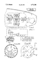
- FIG. 2 is a simplified diagram of the motion sensor of the present invention.
- FIG. 3A is a cross-sectional view of a preferred embodiment of the motion sensor of the present invention.
- FIG. 3B is an outside view of the motion sensor of FIG. 3A.
- FIG. 1 there is shown a block diagram of an pacemaker 12 that is implanted beneath the skin 13 of a patient.
- the pacemaker 12 includes a motion sensor 14. Any motion sensed by the sensor 14 is manifest by a digital signal 16 that is fed directly into the digital circuits 18 of the pacemaker.
- the digital circuits 18 determine when a stimulation pulse should be generated. Operating parameters that control when such a stimulation pulse is to be generated, in addition to the motion signal 16 (described more fully below), include control signals received from an external programmer through telemetry circuits 24, and cardiac activity sensed by analog circuits 26. Many of the control signals received through telemetry circuits 24 are stored in memory 28, as are other controlling parameters.
- the pacemaker 12 can also send signals through the telemetry circuits 24 that are received by an external receiver. As shown in FIG. 1, the external programmer and eternal receiver are typically combined into a single receiver/programmer device 22.
- a trigger signal is presented to the analog circuits 26.
- the analog circuits 26 respond to this trigger signal by generating a stimulation pulse of predetermined amplitude that is delivered to the heart 30 via lead 32 or 34. (It is noted that while two leads, 32 and 34, are shown in FIG. 1, for many applications only one lead would be required.)
- the pacemaker 12 in FIG. 1 operates in conventional manner. Hence, in the description that follows, no additional detail will be provided relative to its operation, except with respect to how the digital pacemaker circuits 18 respond to the motion signal 16 generated by the sensor 14. Before explaining this response, however, it will be helpful to describe the sensor 14 and the manner in which the digital motion signal 16 is generated.
- the sensor includes an enclosed housing 40 having a cavity 42 therein.
- This housing is made from a non-conductive material, such as glass.
- a conductive element 44 is placed inside the housing 40, within the cavity 42. This conductive element is allowed to freely move within the housing 44 as it is subjected to external forces, such as the force of gravity or forces caused by motion of the sensor 40.
- the cavity 42 is evacuated of all gases, i.e., it is a vacuum, and the conductive element 44 is a bead of liquid mercury.
- any conductive material whether a solid, liquid, or gas, could of course be used for this purpose so long as it moves within the cavity 42 when subjected to external forces.
- the force of gravity (sometimes referred to herein as the gravity vector) causes the conductive element 44 to roll, flow, or slide to its lowest possible point within the cavity 42.
- forces are generated according to well-established laws of physics that force the conductive element 44 away from this lowest point.
- Electrodes 46-51 are shown in the drawing.
- the conductive element is sized, and the electrodes are spaced apart, such that the conductive element always makes momentary simultaneous contact with at least two of the electrodes.
- the conductive element 44 is shown in electrical contact with electrodes 46 and 49. If the housing 40 were tipped so that the right side thereof became lower than the left side, thereby causing the force of gravity to move the conductive element 44 from the left to the right of the housing, or if some other force were applied so as to cause the conductive element to move left-to-right, the conductive element 44 would in sequence break the contact between electrodes 46 and 49, make and break contact with electrodes 47 and 50, and then make contact with electrodes 48 and 51.
- OR gate 54 represents the motion of the conductive element 44 from the left side of the housing 40 to the right side. That is, as shown in FIG. 1, the signal will first be high (at the Vdd level) representing the making of contact between electrodes 46 and 49. It will then go low, representing the breaking of the contact betwen electrodes 46 and 49. It then goes high again, representing the making of contact between electrodes 47 and 50; and then goes low again, representing the breaking of contact between electrodes 47 and 50. Finally, it goes high, representing the making of contact between electrodes 48 and 51.
- the gravity vector causes the conductive element 44 to move first left-to-right and then right-to-left within the cavity 42.
- Other force could be applied to cause this same back and forth motion.
- back and forth motion of the conductive element 44 causes a train of pulses to be generated at the output of gate 54.
- the width of the pulses and the interpulse spacing are representative of the velocity of the conductive element 44 as it so moves.
- the OR gate 54 and pull-up resistors R1-R3 shown in the simplified diagram of FIG. 2, may comprise part of the digital logic circuits 18 of the pacemaker 12.
- the pull-up resistors R1-R3 may be very large in value, thereby keeping current flow to a minimum.
- the equivalent of the pull-up resistors R1-R3 may be realized using other CMOS components, thereby effectively reducing any power consumption associated with the sensor 14 to extremely low values.
- FIG. 3A which is a cross-sectional view of the sensor
- the housing 40' is a hollow sphere made from glass or other suitable non-conductive material.
- a matrix of spaced-apart electrodes 60-68 is shown in the figure.
- a conductive element 44' is allowed to roll or flow.
- the preferred material for the conductive element 44' is mercury. As is known in the art, for all temperatures of concern, mercury is a liquid.
- the rolling or movement of the conductive element 44 can be detected by connecting the electrodes in a scheme such as that shown in FIG. 3B where the electrodes 60-64 are connected to a common reference potential Vss, and the electrodes 65-68 are connected to a different reference potential Vdd through respective pull-up resistors, or equivalent.
- the electrodes 60-64 are labeled "-", indicating they are tied to Vss, the most negative potential; and electrodes 65-68 are labeled "+”, indicating they are coupled to Vdd, the most positive potential.
- the "+" electrodes 65-68 are then also connected to the appropriate logic circuits.
- the pulse width and interpulse interval (i.e., the period) of the pulse train generated by the sensor 14 of the present invention provide a measure of the physical motion of the patient. This is because the force of gravity causes the conductive element 44' to be pulled to its lowest possible position within the housing 40'. If the patient were able to hold perfectly still, without any motion whatsoever, the conductive element 44' would not move away from this rest position. (The term "rest position” is used herein to indicate that position to which the conductive element is forced by the gravity vector.) However, any physical activity or motion of the patient, no matter how slight, causes other forces to be generated that displace the conductive element 44' away from its rest position.
- the digital circuitry 18 processes the motion signal 16, using conventional techniques, in order to determine whether the signal has a high frequency (period) or short pulse width, or both. If so, a determination is made that the patient has begun a high activity phase. However, before altering the operation of the pacemaker, the digital circuits monitor the sensed activity to determine if this high activity phase continues over a prescribed period of time. For example, a short burst of a high frequency motion signal could be caused by something or someone simply bumping into the patient, and there would generally be no need to adjust the pacemakers's operation.
- the patient is probably moving more vigorously than normal, and an adjustment of the pacemaker's pacing rate (which includes adjusting the escape interval of a demand-type pacemaker) is in order.
- a prescribed period of time such as 30-45 seconds
- the sensor 14 of the present invention responds to all motion of the patient, even talking and breathing. However, these lower-level motion activities can be distinguished because they will have an average frequency and/or pulse width associated therewith that can be detected.
- the digital processing circuits 18 will recognize this lower-level type of activity or motion and simply save it as a reference level. This reference level could, of course, change over a period of time. This reference level (and by "reference level” it is meant the frequency or period and/or average pulse width of the motion signal) could then be compared against the present motion signal level in order to determine if any significant changes exist that have been maintained for the requisite time period. If so, appropriate adjustments could be made, upward or downward as required, in the basic pacing rate set by the pacemaker.
Abstract
Description
Claims (9)
Priority Applications (2)
| Application Number | Priority Date | Filing Date | Title |
|---|---|---|---|
| US07/003,433 US4771780A (en) | 1987-01-15 | 1987-01-15 | Rate-responsive pacemaker having digital motion sensor |
| US07/172,610 US5010893A (en) | 1987-01-15 | 1988-03-24 | Motion sensor for implanted medical device |
Applications Claiming Priority (1)
| Application Number | Priority Date | Filing Date | Title |
|---|---|---|---|
| US07/003,433 US4771780A (en) | 1987-01-15 | 1987-01-15 | Rate-responsive pacemaker having digital motion sensor |
Related Child Applications (1)
| Application Number | Title | Priority Date | Filing Date |
|---|---|---|---|
| US07/172,610 Continuation-In-Part US5010893A (en) | 1987-01-15 | 1988-03-24 | Motion sensor for implanted medical device |
Publications (1)
| Publication Number | Publication Date |
|---|---|
| US4771780A true US4771780A (en) | 1988-09-20 |
Family
ID=21705849
Family Applications (1)
| Application Number | Title | Priority Date | Filing Date |
|---|---|---|---|
| US07/003,433 Expired - Lifetime US4771780A (en) | 1987-01-15 | 1987-01-15 | Rate-responsive pacemaker having digital motion sensor |
Country Status (1)
| Country | Link |
|---|---|
| US (1) | US4771780A (en) |
Cited By (93)
| Publication number | Priority date | Publication date | Assignee | Title |
|---|---|---|---|---|
| US4846195A (en) * | 1987-03-19 | 1989-07-11 | Intermedics, Inc. | Implantable position and motion sensor |
| US4869251A (en) * | 1986-07-15 | 1989-09-26 | Siemens Aktiengesellschaft | Implantable heart pacemaker with a sensor for inertial and/or rotational movements of the user |
| US4926863A (en) * | 1986-09-12 | 1990-05-22 | Intermedics, Inc. | Rate responsive cardiac pacemaker |
| US4966146A (en) * | 1988-01-14 | 1990-10-30 | Webb Stuart C | Rate-responsive pacemaker |
| US5031614A (en) * | 1986-09-12 | 1991-07-16 | Eckhard Alt | Pacemaker rate control using amplitude and frequency of activity signal |
| US5044365A (en) * | 1988-02-17 | 1991-09-03 | Webb Stuart C | Rate-responsive pacemaker |
| US5052388A (en) * | 1989-12-22 | 1991-10-01 | Medtronic, Inc. | Method and apparatus for implementing activity sensing in a pulse generator |
| FR2685642A1 (en) * | 1991-12-31 | 1993-07-02 | Ela Medical Sa | FREQUENCY HEART STIMULATOR FOR THE PATIENT. |
| US5233984A (en) * | 1991-03-29 | 1993-08-10 | Medtronic, Inc. | Implantable multi-axis position and activity sensor |
| US5318596A (en) * | 1991-11-13 | 1994-06-07 | Exonic Corporation | Activity sensing pacemaker |
| US5336243A (en) * | 1989-11-29 | 1994-08-09 | Biotronik Mess- Und Therapiegerate Gmbh & Co., Ingenieurburo Berlin | Physiologically controlled pacemaker and pacemaker control system with detection of the spatial position of the patient |
| US5342404A (en) * | 1992-04-03 | 1994-08-30 | Intermedics, Inc. | Implantable medical interventional device |
| US5354317A (en) * | 1992-04-03 | 1994-10-11 | Intermedics, Inc. | Apparatus and method for cardiac pacing responsive to patient position |
| US5360436A (en) * | 1992-04-03 | 1994-11-01 | Intermedics, Inc. | Cardiac pacing responsive to multiple activity types |
| US5425750A (en) * | 1993-07-14 | 1995-06-20 | Pacesetter, Inc. | Accelerometer-based multi-axis physical activity sensor for a rate-responsive pacemaker and method of fabrication |
| EP0778049A2 (en) | 1995-12-05 | 1997-06-11 | SORIN BIOMEDICA CARDIO S.p.A. | A heart pacemaker with a variable stimulation frequency |
| WO1998000197A1 (en) * | 1996-06-28 | 1998-01-08 | Medtronic, Inc. | Pacemaker with stair climbing discrimination |
| US5882352A (en) * | 1995-05-25 | 1999-03-16 | Pacesetter, Inc. | Automatic adjustment of detection rate threshold in an implantable antitachycardia therapy device |
| US5935153A (en) * | 1996-11-21 | 1999-08-10 | Ela Medical S.A. | Active implantable medical device enslaved to a signal of acceleration |
| US6171264B1 (en) * | 1998-05-15 | 2001-01-09 | Biosys Ab | Medical measuring system |
| US20010011543A1 (en) * | 1999-08-12 | 2001-08-09 | Peter Forsell | Controlled food flow in a patient |
| US6591143B1 (en) * | 1997-11-24 | 2003-07-08 | Pacesetter Ab | Bending sensor for an implantable lead and a heart stimulator with a lead having such a sensor |
| US20040215265A1 (en) * | 2003-04-23 | 2004-10-28 | Keizer Diederick M. | Sensing techniques for implantable medical devices |
| US20050209643A1 (en) * | 2004-03-16 | 2005-09-22 | Heruth Kenneth T | Controlling therapy based on sleep quality |
| US20050209645A1 (en) * | 2004-03-16 | 2005-09-22 | Heruth Kenneth T | Collecting posture information to evaluate therapy |
| US20050209512A1 (en) * | 2004-03-16 | 2005-09-22 | Heruth Kenneth T | Detecting sleep |
| US20050209644A1 (en) * | 2004-03-16 | 2005-09-22 | Heruth Kenneth T | Collecting activity information to evaluate therapy |
| US20050209513A1 (en) * | 2004-03-16 | 2005-09-22 | Heruth Kenneth T | Collecting sleep quality information via a medical device |
| US20050209511A1 (en) * | 2004-03-16 | 2005-09-22 | Heruth Kenneth T | Collecting activity and sleep quality information via a medical device |
| US20050216064A1 (en) * | 2004-03-16 | 2005-09-29 | Heruth Kenneth T | Sensitivity analysis for selecting therapy parameter sets |
| US20050245988A1 (en) * | 2004-04-14 | 2005-11-03 | Medtronic, Inc. | Collecting posture and activity information to evaluate therapy |
| US20060052832A1 (en) * | 2002-10-31 | 2006-03-09 | Kenneth Dowling | New motion sensor |
| US20060235482A1 (en) * | 2000-02-14 | 2006-10-19 | Obtech Medicalag | Controlled penile prosthesis |
| US20070015976A1 (en) * | 2005-06-01 | 2007-01-18 | Medtronic, Inc. | Correlating a non-polysomnographic physiological parameter set with sleep states |
| US20070123758A1 (en) * | 2004-03-16 | 2007-05-31 | Medtronic, Inc. | Determination of sleep quality for neurological disorders |
| US20070129622A1 (en) * | 2005-12-02 | 2007-06-07 | Medtronic, Inc. | Wearable ambulatory data recorder |
| US20070250121A1 (en) * | 2004-03-16 | 2007-10-25 | Medtronic, Inc. | Collecting activity information to evaluate therapy |
| US20070250134A1 (en) * | 2006-03-24 | 2007-10-25 | Medtronic, Inc. | Collecting gait information for evaluation and control of therapy |
| US20070249968A1 (en) * | 2004-03-16 | 2007-10-25 | Medtronic, Inc. | Collecting posture information to evaluate therapy |
| US20070255118A1 (en) * | 2004-04-14 | 2007-11-01 | Medtronic, Inc. | Collecting posture and activity information to evaluate therapy |
| US20070276439A1 (en) * | 2004-03-16 | 2007-11-29 | Medtronic, Inc. | Collecting sleep quality information via a medical device |
| US20080071326A1 (en) * | 2004-03-16 | 2008-03-20 | Medtronic, Inc. | Detecting sleep to evaluate therapy |
| US20080071150A1 (en) * | 2004-03-16 | 2008-03-20 | Medtronic, Inc. | Collecting activity and sleep quality information via a medical device |
| US20080200965A1 (en) * | 2003-01-31 | 2008-08-21 | Potencia Medical Ag | Electrically operable incontinence treatment apparatus |
| US20080200753A1 (en) * | 2003-01-31 | 2008-08-21 | Potencia Medical Ag | Electrically operable incontinence treatment apparatus |
| US20100121415A1 (en) * | 2008-07-11 | 2010-05-13 | Medtronic, Inc. | Patient interaction with posture-responsive therapy |
| US20100312164A1 (en) * | 2008-01-28 | 2010-12-09 | Peter Forsell | Implantable drainage device |
| US7881798B2 (en) | 2004-03-16 | 2011-02-01 | Medtronic Inc. | Controlling therapy based on sleep quality |
| US7931582B2 (en) | 2000-02-11 | 2011-04-26 | Obtech Medical Ag | Controlled impotence treatment |
| US20110218460A1 (en) * | 2010-03-08 | 2011-09-08 | Seiko Epson Corporation | Fall detecting device and fall detecting method |
| US8096939B2 (en) | 2000-02-10 | 2012-01-17 | Obtech Medical Ag | Urinary incontinence treatment with wireless energy supply |
| US8096938B2 (en) | 1999-08-12 | 2012-01-17 | Obtech Medical Ag | Controlled anal incontinence disease treatment |
| US8150531B2 (en) | 2008-07-11 | 2012-04-03 | Medtronic, Inc. | Associating therapy adjustments with patient posture states |
| US8175720B2 (en) | 2009-04-30 | 2012-05-08 | Medtronic, Inc. | Posture-responsive therapy control based on patient input |
| US8209028B2 (en) | 2008-07-11 | 2012-06-26 | Medtronic, Inc. | Objectification of posture state-responsive therapy based on patient therapy adjustments |
| US8219206B2 (en) | 2008-07-11 | 2012-07-10 | Medtronic, Inc. | Dwell time adjustments for posture state-responsive therapy |
| US8231555B2 (en) | 2009-04-30 | 2012-07-31 | Medtronic, Inc. | Therapy system including multiple posture sensors |
| US8280517B2 (en) | 2008-09-19 | 2012-10-02 | Medtronic, Inc. | Automatic validation techniques for validating operation of medical devices |
| US8290594B2 (en) | 2000-02-11 | 2012-10-16 | Obtech Medical Ag | Impotence treatment apparatus with energy transforming means |
| US8287444B2 (en) | 2000-02-10 | 2012-10-16 | Obtech Medical Ag | Mechanical impotence treatment apparatus |
| US8313423B2 (en) | 2000-02-14 | 2012-11-20 | Peter Forsell | Hydraulic anal incontinence treatment |
| US8388555B2 (en) | 2010-01-08 | 2013-03-05 | Medtronic, Inc. | Posture state classification for a medical device |
| US8396565B2 (en) | 2003-09-15 | 2013-03-12 | Medtronic, Inc. | Automatic therapy adjustments |
| US8401666B2 (en) | 2008-07-11 | 2013-03-19 | Medtronic, Inc. | Modification profiles for posture-responsive therapy |
| US8437861B2 (en) | 2008-07-11 | 2013-05-07 | Medtronic, Inc. | Posture state redefinition based on posture data and therapy adjustments |
| US8504150B2 (en) | 2008-07-11 | 2013-08-06 | Medtronic, Inc. | Associating therapy adjustments with posture states using a stability timer |
| US8509894B2 (en) | 2008-10-10 | 2013-08-13 | Milux Holding Sa | Heart help device, system, and method |
| US8545384B2 (en) | 1999-08-12 | 2013-10-01 | Obtech Medical Ag | Anal incontinence disease treatment with controlled wireless energy supply |
| US8556796B2 (en) | 2000-02-10 | 2013-10-15 | Obtech Medical Ag | Controlled urinary incontinence treatment |
| US8579834B2 (en) | 2010-01-08 | 2013-11-12 | Medtronic, Inc. | Display of detected patient posture state |
| US8600510B2 (en) | 2008-10-10 | 2013-12-03 | Milux Holding Sa | Apparatus, system and operation method for the treatment of female sexual dysfunction |
| US8636809B2 (en) | 2008-01-29 | 2014-01-28 | Milux Holding Sa | Device for treating obesity |
| US8678997B2 (en) | 2000-02-14 | 2014-03-25 | Obtech Medical Ag | Male impotence prosthesis apparatus with wireless energy supply |
| US8696745B2 (en) | 2008-10-10 | 2014-04-15 | Kirk Promotion Ltd. | Heart help device, system, and method |
| US8708934B2 (en) | 2008-07-11 | 2014-04-29 | Medtronic, Inc. | Reorientation of patient posture states for posture-responsive therapy |
| US8734318B2 (en) | 2000-02-11 | 2014-05-27 | Obtech Medical Ag | Mechanical anal incontinence |
| US8764627B2 (en) | 2000-02-14 | 2014-07-01 | Obtech Medical Ag | Penile prosthesis |
| US8874215B2 (en) | 2008-10-10 | 2014-10-28 | Peter Forsell | System, an apparatus, and a method for treating a sexual dysfunctional female patient |
| US9050471B2 (en) | 2008-07-11 | 2015-06-09 | Medtronic, Inc. | Posture state display on medical device user interface |
| US9278158B2 (en) | 2002-07-29 | 2016-03-08 | Peter Forsell | Multi-material incontinence treatment construction device |
| US9327070B2 (en) | 2009-04-30 | 2016-05-03 | Medtronic, Inc. | Medical device therapy based on posture and timing |
| US9357949B2 (en) | 2010-01-08 | 2016-06-07 | Medtronic, Inc. | User interface that displays medical therapy and posture data |
| US9427301B2 (en) | 2002-07-29 | 2016-08-30 | Peter Forsell | Durable implant |
| US9566441B2 (en) | 2010-04-30 | 2017-02-14 | Medtronic, Inc. | Detecting posture sensor signal shift or drift in medical devices |
| US9737719B2 (en) | 2012-04-26 | 2017-08-22 | Medtronic, Inc. | Adjustment of therapy based on acceleration |
| US9907959B2 (en) | 2012-04-12 | 2018-03-06 | Medtronic, Inc. | Velocity detection for posture-responsive therapy |
| US9949812B2 (en) | 2009-07-17 | 2018-04-24 | Peter Forsell | Vaginal operation method for the treatment of anal incontinence in women |
| US9956418B2 (en) | 2010-01-08 | 2018-05-01 | Medtronic, Inc. | Graphical manipulation of posture zones for posture-responsive therapy |
| US10219898B2 (en) | 2008-10-10 | 2019-03-05 | Peter Forsell | Artificial valve |
| US10471264B2 (en) | 2005-12-02 | 2019-11-12 | Medtronic, Inc. | Closed-loop therapy adjustment |
| US10952836B2 (en) | 2009-07-17 | 2021-03-23 | Peter Forsell | Vaginal operation method for the treatment of urinary incontinence in women |
| US11123171B2 (en) | 2008-10-10 | 2021-09-21 | Peter Forsell | Fastening means for implantable medical control assembly |
| US11596795B2 (en) | 2017-07-31 | 2023-03-07 | Medtronic, Inc. | Therapeutic electrical stimulation therapy for patient gait freeze |
Citations (12)
| Publication number | Priority date | Publication date | Assignee | Title |
|---|---|---|---|---|
| US3204637A (en) * | 1963-02-07 | 1965-09-07 | Erich J Frank | Stimulating apparatus |
| US3557796A (en) * | 1969-03-10 | 1971-01-26 | Cordis Corp | Digital counter driven pacer |
| US3593718A (en) * | 1967-07-13 | 1971-07-20 | Biocybernetics Inc | Physiologically controlled cardiac pacer |
| US3943936A (en) * | 1970-09-21 | 1976-03-16 | Rasor Associates, Inc. | Self powered pacers and stimulators |
| US4140132A (en) * | 1978-03-23 | 1979-02-20 | Dahl Joseph D | Variable rate timer for a cardiac pacemaker |
| US4202339A (en) * | 1977-04-21 | 1980-05-13 | Alexander Wirtzfeld | Cardiac pacemaker |
| US4228803A (en) * | 1978-06-23 | 1980-10-21 | Credit Du Nord International N.V. | Physiologically adaptive cardiac pacemaker |
| US4284986A (en) * | 1980-06-23 | 1981-08-18 | Carlos Amortegui | Shirt-pocket medical alert device |
| US4428378A (en) * | 1981-11-19 | 1984-01-31 | Medtronic, Inc. | Rate adaptive pacer |
| US4436092A (en) * | 1982-05-19 | 1984-03-13 | Purdue Research Foundation | Exercise responsive cardiac pacemaker |
| US4567892A (en) * | 1982-03-16 | 1986-02-04 | Gianni Plicchi | Implantable cardiac pacemaker |
| US4596251A (en) * | 1984-02-07 | 1986-06-24 | Gianni Plicchi | Minute ventilation dependent rate responsive pacer |
-
1987
- 1987-01-15 US US07/003,433 patent/US4771780A/en not_active Expired - Lifetime
Patent Citations (13)
| Publication number | Priority date | Publication date | Assignee | Title |
|---|---|---|---|---|
| US3204637A (en) * | 1963-02-07 | 1965-09-07 | Erich J Frank | Stimulating apparatus |
| US3593718A (en) * | 1967-07-13 | 1971-07-20 | Biocybernetics Inc | Physiologically controlled cardiac pacer |
| US3557796A (en) * | 1969-03-10 | 1971-01-26 | Cordis Corp | Digital counter driven pacer |
| US3943936A (en) * | 1970-09-21 | 1976-03-16 | Rasor Associates, Inc. | Self powered pacers and stimulators |
| US4202339A (en) * | 1977-04-21 | 1980-05-13 | Alexander Wirtzfeld | Cardiac pacemaker |
| US4140132A (en) * | 1978-03-23 | 1979-02-20 | Dahl Joseph D | Variable rate timer for a cardiac pacemaker |
| US4228803A (en) * | 1978-06-23 | 1980-10-21 | Credit Du Nord International N.V. | Physiologically adaptive cardiac pacemaker |
| US4284986A (en) * | 1980-06-23 | 1981-08-18 | Carlos Amortegui | Shirt-pocket medical alert device |
| US4428378A (en) * | 1981-11-19 | 1984-01-31 | Medtronic, Inc. | Rate adaptive pacer |
| US4567892A (en) * | 1982-03-16 | 1986-02-04 | Gianni Plicchi | Implantable cardiac pacemaker |
| US4436092A (en) * | 1982-05-19 | 1984-03-13 | Purdue Research Foundation | Exercise responsive cardiac pacemaker |
| US4436092B1 (en) * | 1982-05-19 | 1990-09-25 | Purdue Research Foundation | |
| US4596251A (en) * | 1984-02-07 | 1986-06-24 | Gianni Plicchi | Minute ventilation dependent rate responsive pacer |
Cited By (206)
| Publication number | Priority date | Publication date | Assignee | Title |
|---|---|---|---|---|
| US4869251A (en) * | 1986-07-15 | 1989-09-26 | Siemens Aktiengesellschaft | Implantable heart pacemaker with a sensor for inertial and/or rotational movements of the user |
| US5031615A (en) * | 1986-09-12 | 1991-07-16 | Intermedics, Inc. | Rate responsive cardiac pacemaker |
| US4926863A (en) * | 1986-09-12 | 1990-05-22 | Intermedics, Inc. | Rate responsive cardiac pacemaker |
| US5014700A (en) * | 1986-09-12 | 1991-05-14 | Intermedics, Inc. | Rate responsive cardiac pacemaker |
| US5014704A (en) * | 1986-09-12 | 1991-05-14 | Intermedics, Inc. | Rate responsive cardiac pacemaker |
| US5014703A (en) * | 1986-09-12 | 1991-05-14 | Intermedics, Inc. | Rate responsive cardiac pacemaker |
| US5014702A (en) * | 1986-09-12 | 1991-05-14 | Intermedics, Inc. | Rate responsive cardiac pacemaker |
| US5031614A (en) * | 1986-09-12 | 1991-07-16 | Eckhard Alt | Pacemaker rate control using amplitude and frequency of activity signal |
| US5044366A (en) * | 1986-09-12 | 1991-09-03 | Intermedics, Inc. | Rate responsive cardiac pacemaker |
| US4846195A (en) * | 1987-03-19 | 1989-07-11 | Intermedics, Inc. | Implantable position and motion sensor |
| US4966146A (en) * | 1988-01-14 | 1990-10-30 | Webb Stuart C | Rate-responsive pacemaker |
| US5044365A (en) * | 1988-02-17 | 1991-09-03 | Webb Stuart C | Rate-responsive pacemaker |
| US5063927A (en) * | 1988-02-17 | 1991-11-12 | Webb Stuart C | Rate-responsive pacemaker |
| US5336243A (en) * | 1989-11-29 | 1994-08-09 | Biotronik Mess- Und Therapiegerate Gmbh & Co., Ingenieurburo Berlin | Physiologically controlled pacemaker and pacemaker control system with detection of the spatial position of the patient |
| US5052388A (en) * | 1989-12-22 | 1991-10-01 | Medtronic, Inc. | Method and apparatus for implementing activity sensing in a pulse generator |
| US5233984A (en) * | 1991-03-29 | 1993-08-10 | Medtronic, Inc. | Implantable multi-axis position and activity sensor |
| US5318596A (en) * | 1991-11-13 | 1994-06-07 | Exonic Corporation | Activity sensing pacemaker |
| EP0550293A1 (en) * | 1991-12-31 | 1993-07-07 | ELA MEDICAL (Société anonyme) | Cardiac pacemaker with a stimulation frequency controlled by the patient's effort |
| US5330510A (en) * | 1991-12-31 | 1994-07-19 | Ela Medical | Pacemaker with patient effort-controlled frequency |
| FR2685642A1 (en) * | 1991-12-31 | 1993-07-02 | Ela Medical Sa | FREQUENCY HEART STIMULATOR FOR THE PATIENT. |
| US5342404A (en) * | 1992-04-03 | 1994-08-30 | Intermedics, Inc. | Implantable medical interventional device |
| US5354317A (en) * | 1992-04-03 | 1994-10-11 | Intermedics, Inc. | Apparatus and method for cardiac pacing responsive to patient position |
| US5360436A (en) * | 1992-04-03 | 1994-11-01 | Intermedics, Inc. | Cardiac pacing responsive to multiple activity types |
| US5425750A (en) * | 1993-07-14 | 1995-06-20 | Pacesetter, Inc. | Accelerometer-based multi-axis physical activity sensor for a rate-responsive pacemaker and method of fabrication |
| US5725562A (en) * | 1995-03-30 | 1998-03-10 | Medtronic Inc | Rate responsive cardiac pacemaker and method for discriminating stair climbing from other activities |
| US5957957A (en) * | 1995-03-30 | 1999-09-28 | Medtronic, Inc. | Rate responsive cardiac pacemaker with tilt sensor |
| US5882352A (en) * | 1995-05-25 | 1999-03-16 | Pacesetter, Inc. | Automatic adjustment of detection rate threshold in an implantable antitachycardia therapy device |
| EP0778049A2 (en) | 1995-12-05 | 1997-06-11 | SORIN BIOMEDICA CARDIO S.p.A. | A heart pacemaker with a variable stimulation frequency |
| WO1998000197A1 (en) * | 1996-06-28 | 1998-01-08 | Medtronic, Inc. | Pacemaker with stair climbing discrimination |
| US5935153A (en) * | 1996-11-21 | 1999-08-10 | Ela Medical S.A. | Active implantable medical device enslaved to a signal of acceleration |
| US6591143B1 (en) * | 1997-11-24 | 2003-07-08 | Pacesetter Ab | Bending sensor for an implantable lead and a heart stimulator with a lead having such a sensor |
| US6171264B1 (en) * | 1998-05-15 | 2001-01-09 | Biosys Ab | Medical measuring system |
| US20010011543A1 (en) * | 1999-08-12 | 2001-08-09 | Peter Forsell | Controlled food flow in a patient |
| US8096938B2 (en) | 1999-08-12 | 2012-01-17 | Obtech Medical Ag | Controlled anal incontinence disease treatment |
| US8545384B2 (en) | 1999-08-12 | 2013-10-01 | Obtech Medical Ag | Anal incontinence disease treatment with controlled wireless energy supply |
| US8287444B2 (en) | 2000-02-10 | 2012-10-16 | Obtech Medical Ag | Mechanical impotence treatment apparatus |
| US8602966B2 (en) | 2000-02-10 | 2013-12-10 | Obtech Medical, AG | Mechanical impotence treatment apparatus |
| US8096939B2 (en) | 2000-02-10 | 2012-01-17 | Obtech Medical Ag | Urinary incontinence treatment with wireless energy supply |
| US8556796B2 (en) | 2000-02-10 | 2013-10-15 | Obtech Medical Ag | Controlled urinary incontinence treatment |
| US8290594B2 (en) | 2000-02-11 | 2012-10-16 | Obtech Medical Ag | Impotence treatment apparatus with energy transforming means |
| US7931582B2 (en) | 2000-02-11 | 2011-04-26 | Obtech Medical Ag | Controlled impotence treatment |
| US8734318B2 (en) | 2000-02-11 | 2014-05-27 | Obtech Medical Ag | Mechanical anal incontinence |
| US8313423B2 (en) | 2000-02-14 | 2012-11-20 | Peter Forsell | Hydraulic anal incontinence treatment |
| US8126558B2 (en) | 2000-02-14 | 2012-02-28 | Obtech Medical Ag | Controlled penile prosthesis |
| US8764627B2 (en) | 2000-02-14 | 2014-07-01 | Obtech Medical Ag | Penile prosthesis |
| US8678997B2 (en) | 2000-02-14 | 2014-03-25 | Obtech Medical Ag | Male impotence prosthesis apparatus with wireless energy supply |
| US20060235482A1 (en) * | 2000-02-14 | 2006-10-19 | Obtech Medicalag | Controlled penile prosthesis |
| US9278158B2 (en) | 2002-07-29 | 2016-03-08 | Peter Forsell | Multi-material incontinence treatment construction device |
| US9427301B2 (en) | 2002-07-29 | 2016-08-30 | Peter Forsell | Durable implant |
| US20060052832A1 (en) * | 2002-10-31 | 2006-03-09 | Kenneth Dowling | New motion sensor |
| US7433735B2 (en) * | 2002-10-31 | 2008-10-07 | St. Jude Medical Ab | Motion sensor |
| US20080200753A1 (en) * | 2003-01-31 | 2008-08-21 | Potencia Medical Ag | Electrically operable incontinence treatment apparatus |
| US20080200965A1 (en) * | 2003-01-31 | 2008-08-21 | Potencia Medical Ag | Electrically operable incontinence treatment apparatus |
| US20040215265A1 (en) * | 2003-04-23 | 2004-10-28 | Keizer Diederick M. | Sensing techniques for implantable medical devices |
| US7319899B2 (en) | 2003-04-23 | 2008-01-15 | Medtronic, Inc. | Sensing techniques for implantable medical devices |
| US10130815B2 (en) | 2003-09-15 | 2018-11-20 | Medtronic, Inc. | Automatic therapy adjustments |
| US8396565B2 (en) | 2003-09-15 | 2013-03-12 | Medtronic, Inc. | Automatic therapy adjustments |
| US7395113B2 (en) | 2004-03-16 | 2008-07-01 | Medtronic, Inc. | Collecting activity information to evaluate therapy |
| US7167743B2 (en) | 2004-03-16 | 2007-01-23 | Medtronic, Inc. | Collecting activity information to evaluate therapy |
| US20070276439A1 (en) * | 2004-03-16 | 2007-11-29 | Medtronic, Inc. | Collecting sleep quality information via a medical device |
| US7330760B2 (en) | 2004-03-16 | 2008-02-12 | Medtronic, Inc. | Collecting posture information to evaluate therapy |
| US20080071326A1 (en) * | 2004-03-16 | 2008-03-20 | Medtronic, Inc. | Detecting sleep to evaluate therapy |
| US20080071150A1 (en) * | 2004-03-16 | 2008-03-20 | Medtronic, Inc. | Collecting activity and sleep quality information via a medical device |
| US20080071324A1 (en) * | 2004-03-16 | 2008-03-20 | Medtronic, Inc. | Sensitivity analysis for selecting therapy parameter sets |
| US7366572B2 (en) | 2004-03-16 | 2008-04-29 | Medtronic, Inc. | Controlling therapy based on sleep quality |
| US20050209643A1 (en) * | 2004-03-16 | 2005-09-22 | Heruth Kenneth T | Controlling therapy based on sleep quality |
| US20080177355A1 (en) * | 2004-03-16 | 2008-07-24 | Medtronic, Inc. | Collecting activity information to evaluate therapy |
| US20070249968A1 (en) * | 2004-03-16 | 2007-10-25 | Medtronic, Inc. | Collecting posture information to evaluate therapy |
| US20050209645A1 (en) * | 2004-03-16 | 2005-09-22 | Heruth Kenneth T | Collecting posture information to evaluate therapy |
| US20070250121A1 (en) * | 2004-03-16 | 2007-10-25 | Medtronic, Inc. | Collecting activity information to evaluate therapy |
| US7447545B2 (en) | 2004-03-16 | 2008-11-04 | Medtronic, Inc. | Collecting posture information to evaluate therapy |
| US7491181B2 (en) | 2004-03-16 | 2009-02-17 | Medtronic, Inc. | Collecting activity and sleep quality information via a medical device |
| US20090118599A1 (en) * | 2004-03-16 | 2009-05-07 | Medtronic, Inc. | Collecting activity and sleep quality information via a medical device |
| US7542803B2 (en) | 2004-03-16 | 2009-06-02 | Medtronic, Inc. | Sensitivity analysis for selecting therapy parameter sets |
| US7590455B2 (en) | 2004-03-16 | 2009-09-15 | Medtronic, Inc. | Controlling therapy based on sleep quality |
| US7590453B2 (en) | 2004-03-16 | 2009-09-15 | Medtronic, Inc. | Collecting activity information to evaluate incontinence therapy |
| US20090306740A1 (en) * | 2004-03-16 | 2009-12-10 | Medtronic, Inc. | Controlling therapy based on sleep quality |
| US11096591B2 (en) | 2004-03-16 | 2021-08-24 | Medtronic, Inc. | Determination of sleep quality for neurological disorders |
| US7717848B2 (en) | 2004-03-16 | 2010-05-18 | Medtronic, Inc. | Collecting sleep quality information via a medical device |
| US20100174155A1 (en) * | 2004-03-16 | 2010-07-08 | Medtronic, Inc. | Collecting sleep quality information via a medical device |
| US7775993B2 (en) | 2004-03-16 | 2010-08-17 | Medtronic, Inc. | Detecting sleep |
| US7792583B2 (en) | 2004-03-16 | 2010-09-07 | Medtronic, Inc. | Collecting posture information to evaluate therapy |
| US7805196B2 (en) | 2004-03-16 | 2010-09-28 | Medtronic, Inc. | Collecting activity information to evaluate therapy |
| US20100305665A1 (en) * | 2004-03-16 | 2010-12-02 | Medtronic, Inc. | Collecting posture information to evaluate therapy |
| US20050209512A1 (en) * | 2004-03-16 | 2005-09-22 | Heruth Kenneth T | Detecting sleep |
| US7881798B2 (en) | 2004-03-16 | 2011-02-01 | Medtronic Inc. | Controlling therapy based on sleep quality |
| US7908013B2 (en) | 2004-03-16 | 2011-03-15 | Medtronic, Inc. | Collecting activity information to evaluate therapy |
| US8725244B2 (en) | 2004-03-16 | 2014-05-13 | Medtronic, Inc. | Determination of sleep quality for neurological disorders |
| US8447401B2 (en) | 2004-03-16 | 2013-05-21 | Medtronic, Inc. | Collecting posture information to evaluate therapy |
| US20050209644A1 (en) * | 2004-03-16 | 2005-09-22 | Heruth Kenneth T | Collecting activity information to evaluate therapy |
| US8396554B2 (en) | 2004-03-16 | 2013-03-12 | Medtronic, Inc. | Collecting posture information to evaluate therapy |
| US8032224B2 (en) | 2004-03-16 | 2011-10-04 | Medtronic, Inc. | Sensitivity analysis for selecting therapy parameter sets |
| US8055348B2 (en) | 2004-03-16 | 2011-11-08 | Medtronic, Inc. | Detecting sleep to evaluate therapy |
| US20050209513A1 (en) * | 2004-03-16 | 2005-09-22 | Heruth Kenneth T | Collecting sleep quality information via a medical device |
| US20070123758A1 (en) * | 2004-03-16 | 2007-05-31 | Medtronic, Inc. | Determination of sleep quality for neurological disorders |
| US8758242B2 (en) | 2004-03-16 | 2014-06-24 | Medtronic, Inc. | Collecting sleep quality information via a medical device |
| US8337431B2 (en) | 2004-03-16 | 2012-12-25 | Medtronic, Inc. | Collecting activity and sleep quality information via a medical device |
| US10300283B2 (en) | 2004-03-16 | 2019-05-28 | Medtronic, Inc. | Determination of sleep quality for neurological disorders |
| US8335568B2 (en) | 2004-03-16 | 2012-12-18 | Medtronic, Inc. | Controlling therapy based on sleep quality |
| US8190253B2 (en) | 2004-03-16 | 2012-05-29 | Medtronic, Inc. | Collecting activity information to evaluate incontinence therapy |
| US8332038B2 (en) | 2004-03-16 | 2012-12-11 | Medtronic, Inc. | Detecting sleep to evaluate therapy |
| US20050209511A1 (en) * | 2004-03-16 | 2005-09-22 | Heruth Kenneth T | Collecting activity and sleep quality information via a medical device |
| US8792982B2 (en) | 2004-03-16 | 2014-07-29 | Medtronic, Inc. | Collecting posture information to evaluate therapy |
| US9623248B2 (en) | 2004-03-16 | 2017-04-18 | Medtronic, Inc. | Collecting sleep quality information via a medical device |
| US20050215947A1 (en) * | 2004-03-16 | 2005-09-29 | Heruth Kenneth T | Controlling therapy based on sleep quality |
| US20050234514A1 (en) * | 2004-03-16 | 2005-10-20 | Heruth Kenneth T | Collecting posture information to evaluate therapy |
| US20050222643A1 (en) * | 2004-03-16 | 2005-10-06 | Heruth Kenneth T | Collecting activity information to evaluate therapy |
| US8308661B2 (en) | 2004-03-16 | 2012-11-13 | Medtronic, Inc. | Collecting activity and sleep quality information via a medical device |
| US20050222522A1 (en) * | 2004-03-16 | 2005-10-06 | Heruth Kenneth T | Detecting sleep |
| US20050216064A1 (en) * | 2004-03-16 | 2005-09-29 | Heruth Kenneth T | Sensitivity analysis for selecting therapy parameter sets |
| US8135473B2 (en) | 2004-04-14 | 2012-03-13 | Medtronic, Inc. | Collecting posture and activity information to evaluate therapy |
| US20070255118A1 (en) * | 2004-04-14 | 2007-11-01 | Medtronic, Inc. | Collecting posture and activity information to evaluate therapy |
| US8688221B2 (en) | 2004-04-14 | 2014-04-01 | Medtronic, Inc. | Collecting posture and activity information to evaluate therapy |
| US20050245988A1 (en) * | 2004-04-14 | 2005-11-03 | Medtronic, Inc. | Collecting posture and activity information to evaluate therapy |
| US7313440B2 (en) | 2004-04-14 | 2007-12-25 | Medtronic, Inc. | Collecting posture and activity information to evaluate therapy |
| US8021299B2 (en) | 2005-06-01 | 2011-09-20 | Medtronic, Inc. | Correlating a non-polysomnographic physiological parameter set with sleep states |
| US20070015976A1 (en) * | 2005-06-01 | 2007-01-18 | Medtronic, Inc. | Correlating a non-polysomnographic physiological parameter set with sleep states |
| US20070129769A1 (en) * | 2005-12-02 | 2007-06-07 | Medtronic, Inc. | Wearable ambulatory data recorder |
| US8016776B2 (en) | 2005-12-02 | 2011-09-13 | Medtronic, Inc. | Wearable ambulatory data recorder |
| US8444578B2 (en) | 2005-12-02 | 2013-05-21 | Medtronic, Inc. | Wearable ambulatory data recorder |
| US20070129622A1 (en) * | 2005-12-02 | 2007-06-07 | Medtronic, Inc. | Wearable ambulatory data recorder |
| US10471264B2 (en) | 2005-12-02 | 2019-11-12 | Medtronic, Inc. | Closed-loop therapy adjustment |
| US9592379B2 (en) | 2006-03-24 | 2017-03-14 | Medtronic, Inc. | Collecting gait information for evaluation and control of therapy |
| US8744587B2 (en) | 2006-03-24 | 2014-06-03 | Medtronic, Inc. | Collecting gait information for evaluation and control of therapy |
| US10251595B2 (en) | 2006-03-24 | 2019-04-09 | Medtronic, Inc. | Collecting gait information for evaluation and control of therapy |
| US20070250134A1 (en) * | 2006-03-24 | 2007-10-25 | Medtronic, Inc. | Collecting gait information for evaluation and control of therapy |
| US8961448B2 (en) | 2008-01-28 | 2015-02-24 | Peter Forsell | Implantable drainage device |
| US9694165B2 (en) * | 2008-01-28 | 2017-07-04 | Peter Mats Forsell | Implantable drainage device |
| US20100312164A1 (en) * | 2008-01-28 | 2010-12-09 | Peter Forsell | Implantable drainage device |
| US20150157836A1 (en) * | 2008-01-28 | 2015-06-11 | Peter Mats Forsell | Implantable drainage device |
| US9060771B2 (en) | 2008-01-29 | 2015-06-23 | Peter Forsell | Method and instrument for treating obesity |
| US8636809B2 (en) | 2008-01-29 | 2014-01-28 | Milux Holding Sa | Device for treating obesity |
| US8219206B2 (en) | 2008-07-11 | 2012-07-10 | Medtronic, Inc. | Dwell time adjustments for posture state-responsive therapy |
| US8905948B2 (en) | 2008-07-11 | 2014-12-09 | Medtronic, Inc. | Generation of proportional posture information over multiple time intervals |
| US8583252B2 (en) | 2008-07-11 | 2013-11-12 | Medtronic, Inc. | Patient interaction with posture-responsive therapy |
| US11672989B2 (en) | 2008-07-11 | 2023-06-13 | Medtronic, Inc. | Posture state responsive therapy delivery using dwell times |
| US8515550B2 (en) | 2008-07-11 | 2013-08-20 | Medtronic, Inc. | Assignment of therapy parameter to multiple posture states |
| US8515549B2 (en) | 2008-07-11 | 2013-08-20 | Medtronic, Inc. | Associating therapy adjustments with intended patient posture states |
| US8644945B2 (en) | 2008-07-11 | 2014-02-04 | Medtronic, Inc. | Patient interaction with posture-responsive therapy |
| US20100121415A1 (en) * | 2008-07-11 | 2010-05-13 | Medtronic, Inc. | Patient interaction with posture-responsive therapy |
| US8504150B2 (en) | 2008-07-11 | 2013-08-06 | Medtronic, Inc. | Associating therapy adjustments with posture states using a stability timer |
| US8688225B2 (en) | 2008-07-11 | 2014-04-01 | Medtronic, Inc. | Posture state detection using selectable system control parameters |
| US11004556B2 (en) | 2008-07-11 | 2021-05-11 | Medtronic, Inc. | Associating therapy adjustments with posture states using a stability timer |
| US8708934B2 (en) | 2008-07-11 | 2014-04-29 | Medtronic, Inc. | Reorientation of patient posture states for posture-responsive therapy |
| US8447411B2 (en) | 2008-07-11 | 2013-05-21 | Medtronic, Inc. | Patient interaction with posture-responsive therapy |
| US8437861B2 (en) | 2008-07-11 | 2013-05-07 | Medtronic, Inc. | Posture state redefinition based on posture data and therapy adjustments |
| US8401666B2 (en) | 2008-07-11 | 2013-03-19 | Medtronic, Inc. | Modification profiles for posture-responsive therapy |
| US8751011B2 (en) | 2008-07-11 | 2014-06-10 | Medtronic, Inc. | Defining therapy parameter values for posture states |
| US8755901B2 (en) | 2008-07-11 | 2014-06-17 | Medtronic, Inc. | Patient assignment of therapy parameter to posture state |
| US10925517B2 (en) | 2008-07-11 | 2021-02-23 | Medtronic, Inc. | Posture state redefinition based on posture data |
| US8150531B2 (en) | 2008-07-11 | 2012-04-03 | Medtronic, Inc. | Associating therapy adjustments with patient posture states |
| US8332041B2 (en) | 2008-07-11 | 2012-12-11 | Medtronic, Inc. | Patient interaction with posture-responsive therapy |
| US8326420B2 (en) | 2008-07-11 | 2012-12-04 | Medtronic, Inc. | Associating therapy adjustments with posture states using stability timers |
| US10231650B2 (en) | 2008-07-11 | 2019-03-19 | Medtronic, Inc. | Generation of sleep quality information based on posture state data |
| US8886302B2 (en) | 2008-07-11 | 2014-11-11 | Medtronic, Inc. | Adjustment of posture-responsive therapy |
| US8231556B2 (en) | 2008-07-11 | 2012-07-31 | Medtronic, Inc. | Obtaining baseline patient information |
| US8958885B2 (en) | 2008-07-11 | 2015-02-17 | Medtronic, Inc. | Posture state classification for a medical device |
| US8323218B2 (en) | 2008-07-11 | 2012-12-04 | Medtronic, Inc. | Generation of proportional posture information over multiple time intervals |
| US10207118B2 (en) | 2008-07-11 | 2019-02-19 | Medtronic, Inc. | Associating therapy adjustments with posture states using a stability timer |
| US9050471B2 (en) | 2008-07-11 | 2015-06-09 | Medtronic, Inc. | Posture state display on medical device user interface |
| US8315710B2 (en) | 2008-07-11 | 2012-11-20 | Medtronic, Inc. | Associating therapy adjustments with patient posture states |
| US8282580B2 (en) | 2008-07-11 | 2012-10-09 | Medtronic, Inc. | Data rejection for posture state analysis |
| US8200340B2 (en) | 2008-07-11 | 2012-06-12 | Medtronic, Inc. | Guided programming for posture-state responsive therapy |
| US9968784B2 (en) | 2008-07-11 | 2018-05-15 | Medtronic, Inc. | Posture state redefinition based on posture data |
| US9956412B2 (en) | 2008-07-11 | 2018-05-01 | Medtronic, Inc. | Linking posture states for posture responsive therapy |
| US9272091B2 (en) | 2008-07-11 | 2016-03-01 | Medtronic, Inc. | Posture state display on medical device user interface |
| US9592387B2 (en) | 2008-07-11 | 2017-03-14 | Medtronic, Inc. | Patient-defined posture states for posture responsive therapy |
| US9919159B2 (en) | 2008-07-11 | 2018-03-20 | Medtronic, Inc. | Programming posture responsive therapy |
| US9327129B2 (en) | 2008-07-11 | 2016-05-03 | Medtronic, Inc. | Blended posture state classification and therapy delivery |
| US9776008B2 (en) | 2008-07-11 | 2017-10-03 | Medtronic, Inc. | Posture state responsive therapy delivery using dwell times |
| US8209028B2 (en) | 2008-07-11 | 2012-06-26 | Medtronic, Inc. | Objectification of posture state-responsive therapy based on patient therapy adjustments |
| US8249718B2 (en) | 2008-07-11 | 2012-08-21 | Medtronic, Inc. | Programming posture state-responsive therapy with nominal therapy parameters |
| US9440084B2 (en) | 2008-07-11 | 2016-09-13 | Medtronic, Inc. | Programming posture responsive therapy |
| US9662045B2 (en) | 2008-07-11 | 2017-05-30 | Medtronic, Inc. | Generation of sleep quality information based on posture state data |
| US9545518B2 (en) | 2008-07-11 | 2017-01-17 | Medtronic, Inc. | Posture state classification for a medical device |
| US9560990B2 (en) | 2008-07-11 | 2017-02-07 | Medtronic, Inc. | Obtaining baseline patient information |
| US8280517B2 (en) | 2008-09-19 | 2012-10-02 | Medtronic, Inc. | Automatic validation techniques for validating operation of medical devices |
| US9370656B2 (en) | 2008-10-10 | 2016-06-21 | Peter Forsell | System, an apparatus, and a method for treating a sexual dysfunctional female patient |
| US9072907B2 (en) | 2008-10-10 | 2015-07-07 | Peter Forsell | Heart help device, system, and method |
| US8600510B2 (en) | 2008-10-10 | 2013-12-03 | Milux Holding Sa | Apparatus, system and operation method for the treatment of female sexual dysfunction |
| US9526649B2 (en) | 2008-10-10 | 2016-12-27 | Peter Forsell | Method and instrument for treating obesity |
| US11123171B2 (en) | 2008-10-10 | 2021-09-21 | Peter Forsell | Fastening means for implantable medical control assembly |
| US8509894B2 (en) | 2008-10-10 | 2013-08-13 | Milux Holding Sa | Heart help device, system, and method |
| US8696745B2 (en) | 2008-10-10 | 2014-04-15 | Kirk Promotion Ltd. | Heart help device, system, and method |
| US10583234B2 (en) | 2008-10-10 | 2020-03-10 | Peter Forsell | Heart help device, system and method |
| US8874215B2 (en) | 2008-10-10 | 2014-10-28 | Peter Forsell | System, an apparatus, and a method for treating a sexual dysfunctional female patient |
| US10219898B2 (en) | 2008-10-10 | 2019-03-05 | Peter Forsell | Artificial valve |
| US9026223B2 (en) | 2009-04-30 | 2015-05-05 | Medtronic, Inc. | Therapy system including multiple posture sensors |
| US9327070B2 (en) | 2009-04-30 | 2016-05-03 | Medtronic, Inc. | Medical device therapy based on posture and timing |
| US8231555B2 (en) | 2009-04-30 | 2012-07-31 | Medtronic, Inc. | Therapy system including multiple posture sensors |
| US10071197B2 (en) | 2009-04-30 | 2018-09-11 | Medtronic, Inc. | Therapy system including multiple posture sensors |
| US8175720B2 (en) | 2009-04-30 | 2012-05-08 | Medtronic, Inc. | Posture-responsive therapy control based on patient input |
| US10952836B2 (en) | 2009-07-17 | 2021-03-23 | Peter Forsell | Vaginal operation method for the treatment of urinary incontinence in women |
| US9949812B2 (en) | 2009-07-17 | 2018-04-24 | Peter Forsell | Vaginal operation method for the treatment of anal incontinence in women |
| US8758274B2 (en) | 2010-01-08 | 2014-06-24 | Medtronic, Inc. | Automated adjustment of posture state definitions for a medical device |
| US9174055B2 (en) | 2010-01-08 | 2015-11-03 | Medtronic, Inc. | Display of detected patient posture state |
| US8388555B2 (en) | 2010-01-08 | 2013-03-05 | Medtronic, Inc. | Posture state classification for a medical device |
| US9956418B2 (en) | 2010-01-08 | 2018-05-01 | Medtronic, Inc. | Graphical manipulation of posture zones for posture-responsive therapy |
| US9357949B2 (en) | 2010-01-08 | 2016-06-07 | Medtronic, Inc. | User interface that displays medical therapy and posture data |
| US8579834B2 (en) | 2010-01-08 | 2013-11-12 | Medtronic, Inc. | Display of detected patient posture state |
| US9149210B2 (en) | 2010-01-08 | 2015-10-06 | Medtronic, Inc. | Automated calibration of posture state classification for a medical device |
| US20110218460A1 (en) * | 2010-03-08 | 2011-09-08 | Seiko Epson Corporation | Fall detecting device and fall detecting method |
| US9566441B2 (en) | 2010-04-30 | 2017-02-14 | Medtronic, Inc. | Detecting posture sensor signal shift or drift in medical devices |
| US9907959B2 (en) | 2012-04-12 | 2018-03-06 | Medtronic, Inc. | Velocity detection for posture-responsive therapy |
| US9737719B2 (en) | 2012-04-26 | 2017-08-22 | Medtronic, Inc. | Adjustment of therapy based on acceleration |
| US11596795B2 (en) | 2017-07-31 | 2023-03-07 | Medtronic, Inc. | Therapeutic electrical stimulation therapy for patient gait freeze |
Similar Documents
| Publication | Publication Date | Title |
|---|---|---|
| US4771780A (en) | Rate-responsive pacemaker having digital motion sensor | |
| US5010893A (en) | Motion sensor for implanted medical device | |
| US4860751A (en) | Activity sensor for pacemaker control | |
| JP3770911B2 (en) | Medical device using multiple DC accelerometers for patient activity and posture sensing | |
| US6810287B2 (en) | Implantable cardiac disease management device with trigger-stored polysomnogram and phonocardiogram | |
| US5725562A (en) | Rate responsive cardiac pacemaker and method for discriminating stair climbing from other activities | |
| US6466821B1 (en) | AC/DC multi-axis accelerometer for determining patient activity and body position | |
| US6526311B2 (en) | System and method for sensing and detecting far-field R-wave | |
| US5935158A (en) | Electrode lead and device for tissue stimulation and/or detection of tissue response | |
| EP0257116B1 (en) | Apparatus and method for adjusting heart/pacer rate relative to ejection time to obtain a required cardiac output | |
| US7761158B2 (en) | Detection of heart failure decompensation based on cumulative changes in sensor signals | |
| EP1911399B1 (en) | Techniques for correlating thoracic impedance with physiological status | |
| US4846195A (en) | Implantable position and motion sensor | |
| US5360436A (en) | Cardiac pacing responsive to multiple activity types | |
| US5991661A (en) | System and method for measuring cardiac activity | |
| US4467807A (en) | Rate adaptive demand pacemaker | |
| US5931858A (en) | Implantable device for monitoring aerobic capacity of patients | |
| US8423142B2 (en) | Cross-checking of transthoracic impedance and acceleration signals | |
| US7037266B2 (en) | Ultrasound methods and implantable medical devices using same | |
| US6556859B1 (en) | System and method for classifying sensed atrial events in a cardiac pacing system | |
| EP1331968B1 (en) | Method and system for measuring a source impedance of at least one cardiac electrical signal in a mammalian heart | |
| WO1998000197A9 (en) | Pacemaker with stair climbing discrimination | |
| EP0431083A1 (en) | Pacemaker having automatic rate response adjustment. | |
| US4907593A (en) | Adaptation of heart pacing to physical activity | |
| US6650938B2 (en) | Method and system for preventing atrial fibrillation by rapid pacing intervention |
Legal Events
| Date | Code | Title | Description |
|---|---|---|---|
| AS | Assignment |
Owner name: SIEMENS-PACESETTER, INC., SYLMAR, CALIFORNIA, A DE Free format text: ASSIGNMENT OF ASSIGNORS INTEREST.;ASSIGNOR:SHOLDER, JASON A.;REEL/FRAME:004661/0128 Effective date: 19870115 Owner name: SIEMENS-PACESETTER, INC., A DE. CORP., CALIFORNIA Free format text: ASSIGNMENT OF ASSIGNORS INTEREST;ASSIGNOR:SHOLDER, JASON A.;REEL/FRAME:004661/0128 Effective date: 19870115 |
|
| STCF | Information on status: patent grant |
Free format text: PATENTED CASE |
|
| FEPP | Fee payment procedure |
Free format text: PAYOR NUMBER ASSIGNED (ORIGINAL EVENT CODE: ASPN); ENTITY STATUS OF PATENT OWNER: LARGE ENTITY |
|
| FPAY | Fee payment |
Year of fee payment: 4 |
|
| AS | Assignment |
Owner name: PACESETTER, INC., CALIFORNIA Free format text: ASSIGNMENT OF ASSIGNORS INTEREST;ASSIGNOR:SIEMENS PACESETTER, INC.;REEL/FRAME:007388/0042 Effective date: 19940930 |
|
| FPAY | Fee payment |
Year of fee payment: 8 |
|
| FEPP | Fee payment procedure |
Free format text: PAYER NUMBER DE-ASSIGNED (ORIGINAL EVENT CODE: RMPN); ENTITY STATUS OF PATENT OWNER: LARGE ENTITY Free format text: PAYOR NUMBER ASSIGNED (ORIGINAL EVENT CODE: ASPN); ENTITY STATUS OF PATENT OWNER: LARGE ENTITY |
|
| FPAY | Fee payment |
Year of fee payment: 12 |