US4764035A - Molded self-lubricating split-ring bearing assembly - Google Patents
Molded self-lubricating split-ring bearing assembly Download PDFInfo
- Publication number
- US4764035A US4764035A US07/117,802 US11780287A US4764035A US 4764035 A US4764035 A US 4764035A US 11780287 A US11780287 A US 11780287A US 4764035 A US4764035 A US 4764035A
- Authority
- US
- United States
- Prior art keywords
- bearing
- sealing
- bearing member
- structure defined
- groove
- Prior art date
- Legal status (The legal status is an assumption and is not a legal conclusion. Google has not performed a legal analysis and makes no representation as to the accuracy of the status listed.)
- Expired - Lifetime
Links
Images

Classifications
-
- F—MECHANICAL ENGINEERING; LIGHTING; HEATING; WEAPONS; BLASTING
- F16—ENGINEERING ELEMENTS AND UNITS; GENERAL MEASURES FOR PRODUCING AND MAINTAINING EFFECTIVE FUNCTIONING OF MACHINES OR INSTALLATIONS; THERMAL INSULATION IN GENERAL
- F16C—SHAFTS; FLEXIBLE SHAFTS; ELEMENTS OR CRANKSHAFT MECHANISMS; ROTARY BODIES OTHER THAN GEARING ELEMENTS; BEARINGS
- F16C33/00—Parts of bearings; Special methods for making bearings or parts thereof
- F16C33/02—Parts of sliding-contact bearings
- F16C33/04—Brasses; Bushes; Linings
- F16C33/20—Sliding surface consisting mainly of plastics
-
- F—MECHANICAL ENGINEERING; LIGHTING; HEATING; WEAPONS; BLASTING
- F16—ENGINEERING ELEMENTS AND UNITS; GENERAL MEASURES FOR PRODUCING AND MAINTAINING EFFECTIVE FUNCTIONING OF MACHINES OR INSTALLATIONS; THERMAL INSULATION IN GENERAL
- F16C—SHAFTS; FLEXIBLE SHAFTS; ELEMENTS OR CRANKSHAFT MECHANISMS; ROTARY BODIES OTHER THAN GEARING ELEMENTS; BEARINGS
- F16C17/00—Sliding-contact bearings for exclusively rotary movement
- F16C17/02—Sliding-contact bearings for exclusively rotary movement for radial load only
-
- F—MECHANICAL ENGINEERING; LIGHTING; HEATING; WEAPONS; BLASTING
- F16—ENGINEERING ELEMENTS AND UNITS; GENERAL MEASURES FOR PRODUCING AND MAINTAINING EFFECTIVE FUNCTIONING OF MACHINES OR INSTALLATIONS; THERMAL INSULATION IN GENERAL
- F16C—SHAFTS; FLEXIBLE SHAFTS; ELEMENTS OR CRANKSHAFT MECHANISMS; ROTARY BODIES OTHER THAN GEARING ELEMENTS; BEARINGS
- F16C27/00—Elastic or yielding bearings or bearing supports, for exclusively rotary movement
- F16C27/06—Elastic or yielding bearings or bearing supports, for exclusively rotary movement by means of parts of rubber or like materials
- F16C27/063—Sliding contact bearings
-
- F—MECHANICAL ENGINEERING; LIGHTING; HEATING; WEAPONS; BLASTING
- F16—ENGINEERING ELEMENTS AND UNITS; GENERAL MEASURES FOR PRODUCING AND MAINTAINING EFFECTIVE FUNCTIONING OF MACHINES OR INSTALLATIONS; THERMAL INSULATION IN GENERAL
- F16J—PISTONS; CYLINDERS; SEALINGS
- F16J15/00—Sealings
- F16J15/54—Other sealings for rotating shafts
-
- F—MECHANICAL ENGINEERING; LIGHTING; HEATING; WEAPONS; BLASTING
- F16—ENGINEERING ELEMENTS AND UNITS; GENERAL MEASURES FOR PRODUCING AND MAINTAINING EFFECTIVE FUNCTIONING OF MACHINES OR INSTALLATIONS; THERMAL INSULATION IN GENERAL
- F16C—SHAFTS; FLEXIBLE SHAFTS; ELEMENTS OR CRANKSHAFT MECHANISMS; ROTARY BODIES OTHER THAN GEARING ELEMENTS; BEARINGS
- F16C2208/00—Plastics; Synthetic resins, e.g. rubbers
- F16C2208/20—Thermoplastic resins
- F16C2208/60—Polyamides [PA]
-
- F—MECHANICAL ENGINEERING; LIGHTING; HEATING; WEAPONS; BLASTING
- F16—ENGINEERING ELEMENTS AND UNITS; GENERAL MEASURES FOR PRODUCING AND MAINTAINING EFFECTIVE FUNCTIONING OF MACHINES OR INSTALLATIONS; THERMAL INSULATION IN GENERAL
- F16C—SHAFTS; FLEXIBLE SHAFTS; ELEMENTS OR CRANKSHAFT MECHANISMS; ROTARY BODIES OTHER THAN GEARING ELEMENTS; BEARINGS
- F16C2208/00—Plastics; Synthetic resins, e.g. rubbers
- F16C2208/20—Thermoplastic resins
- F16C2208/76—Polyolefins, e.g. polyproylene [PP]
- F16C2208/78—Polyethylene [PE], e.g. ultra-high molecular weight polyethylene [UHMWPE]
-
- F—MECHANICAL ENGINEERING; LIGHTING; HEATING; WEAPONS; BLASTING
- F16—ENGINEERING ELEMENTS AND UNITS; GENERAL MEASURES FOR PRODUCING AND MAINTAINING EFFECTIVE FUNCTIONING OF MACHINES OR INSTALLATIONS; THERMAL INSULATION IN GENERAL
- F16C—SHAFTS; FLEXIBLE SHAFTS; ELEMENTS OR CRANKSHAFT MECHANISMS; ROTARY BODIES OTHER THAN GEARING ELEMENTS; BEARINGS
- F16C2220/00—Shaping
- F16C2220/02—Shaping by casting
- F16C2220/04—Shaping by casting by injection-moulding
-
- Y—GENERAL TAGGING OF NEW TECHNOLOGICAL DEVELOPMENTS; GENERAL TAGGING OF CROSS-SECTIONAL TECHNOLOGIES SPANNING OVER SEVERAL SECTIONS OF THE IPC; TECHNICAL SUBJECTS COVERED BY FORMER USPC CROSS-REFERENCE ART COLLECTIONS [XRACs] AND DIGESTS
- Y10—TECHNICAL SUBJECTS COVERED BY FORMER USPC
- Y10S—TECHNICAL SUBJECTS COVERED BY FORMER USPC CROSS-REFERENCE ART COLLECTIONS [XRACs] AND DIGESTS
- Y10S384/00—Bearings
- Y10S384/90—Cooling or heating
- Y10S384/906—Antirotation key
-
- Y—GENERAL TAGGING OF NEW TECHNOLOGICAL DEVELOPMENTS; GENERAL TAGGING OF CROSS-SECTIONAL TECHNOLOGIES SPANNING OVER SEVERAL SECTIONS OF THE IPC; TECHNICAL SUBJECTS COVERED BY FORMER USPC CROSS-REFERENCE ART COLLECTIONS [XRACs] AND DIGESTS
- Y10—TECHNICAL SUBJECTS COVERED BY FORMER USPC
- Y10S—TECHNICAL SUBJECTS COVERED BY FORMER USPC CROSS-REFERENCE ART COLLECTIONS [XRACs] AND DIGESTS
- Y10S384/00—Bearings
- Y10S384/90—Cooling or heating
- Y10S384/909—Plastic
Definitions
- My invention includes the manufacture, preferably by molding, of a bearing sealing member which is relatively thin and of split-ring construction with overlapping free ends, of a plastic material having inherent self-lubricating qualities with a pressure velocity value of at least 1800 at 100 feet per minute surface speed. This means that a bearing member made of such material will function adequately as a bearing under such conditions. Such a pressure velocity value ensures adequate self-lubricating qualities when utilized as disclosed herein. Pressure velocity value is determined by multiplying the area of the bearing by the pressure applied thereto in p.s.i. and by surface speed, expressed in feet per minute.
- This elastomeric seal and spring is formed of a readily flowable material, such as rubber, and is uniform in cross-section, preferably symmetrical.
- the concavities of said surfaces are approximately 17%-33% of said maximum radial dimensions and the convexity of the lobes are preferably 14%-16% of said maximum radial dimensions, the above relative dimensions will result and provide an adequate seal.
- a ring having these dimensions will adequately support such a bearing-seal under all of its operating conditions, in that it will cause the circumference thereof to adjust in accordance with the variations in circumference of the opposed surfaces between which the seal is perfected.
- the ring will yield as needed to accommodate the required changes in dimensions.
- the ends of the bearing seal will move both circumferentially and axially relative to each other to accommodate such changes in circumference.
- a ring having such dimensions is sufficiently yielding and forgiving so that the material from which it is made will flow into its concavities without undue pressure being applied to the bearing-seal and as a consequence, the bearing-seal will not wear unduly. I have found that such a combination is highly successful, particularly where the circumstances require lubrication for high speed relative movements over extended periods of time.
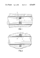
- FIG. 1 is a fragmentary vertical sectional view of a brass bearing with a rapidly rotating steel shaft mounted therein and shown in elevation, with one of my new bearing-seal assemblies perfecting a seal therebetween at its outer diameter;
- FIG. 2 is a similar fragmentary vertical sectional view of a brass bearing with a rapidly rotating steel shaft mounted therein and shown in elevation, with one of my new bearing-seal assemblies perfecting a seal therebetween at its inner diameter;
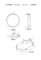
- FIG. 3 is a side elevational view of one of my bearing-seals
- FIG. 4 is a top plan view of the bearing-seal shown in FIG. 3;
- FIG. 5 is a vertical sectional view, taken along line 5--5 of FIG. 3;
- FIG. 6 is a side elevational view of an elastomeric combined seal and spring such as is shown in FIGS. 1-2 behind the bearing-seal;
- FIG. 7 is a vertical sectional view taken along line 7--7 of FIG. 6;
- FIG. 8 is an enlarged vertical sectional view of the ring shown in FIGS. 6-7;
- FIG. 9 is a perspective view of a molded sectional bearing-seal member where the two sections are substantially identical.
- FIGS. 1-2 illustrates the use of my new bearing assembly.
- a bearing-seal member 10 which is thin and of the split-ring type, having ends which overlap.
- This bearing-seal member is made of a plastic material which is either thermosetting or thermoplastic and is self-lubricating, having a pressure velocity value at least equal to 1800 at 100 feet per minute surface speed.
- It also includes an elastomeric combined seal and spring 11 which is made of flowable resilient material, such as rubber, and is sufficiently yieldable and forgiving so as to avoid undue pressure being applied to the backside of the bearing member 10.
- Such a bearing-seal assembly will wear well over long periods of time and under unusually severe circumstances, such as where the relatively moving parts move at high speeds over prolonged periods.
- the bearing member When mounted within a groove, as shown in FIGS. 1-2, the bearing member will adjust to dimensional changes in the moving parts, which reflect the changes in temperature caused by the high speed movement.
- Such a combination perfects a seal at the sealing surface and at the bottom of the groove so as to prevent the loss of lubricant between the moving parts, which will normally result from the differences in co-efficient of expansion of the different materials from which the two parts are made.
- FIG. 1 shows such an installation as described hereinabove within a groove 12 which is formed in the outer circumference of a steel shaft 13, which is rotating at very high speeds within a brass bearing 14, the latter providing a housing for the shaft.
- the outer circumference of the bearing-seal 10 bears against and seals against the sealing surface of the bearing 14 and the elastomeric combined seal and spring 11 exerts a slight pressure outwardly against the backside thereof.
- the seal 11 also seals against the bottom of the groove so as to prevent the escape of lubrication around the assembly.
- FIG. 2 shows a similar rapidly rotating steel shaft 15 mounted within a brass bearing 16.
- the groove 17 is formed in the bearing 16 rather than in the exterior surface of the shaft 15.
- the bearing-seal 10 bears against the exterior surface of the shaft 15 and the elastomeric seal and spring 11 is disposed therebehind within the groove 17 and urges the bearing-seal 10 into sealing relation with the outer circumference of the shaft 15.
- the seal is perfected at the inner diameter of the bearing seal 10, whereas in FIG. 1, the seal is perfected at the outer diameter thereof.
- FIGS. 3-5 show the details of the bearing-seal 10.
- This bearing-seal 10 is preferably molded from a moldable thermoplastic or thermosetting plastic having the inherent self-lubricating qualities described hereinabove as a result of its pressure velocity value of at least equal to 1800 at 100 feet per minute surface speed. As best shown in FIG. 5, it is generally rectangular in cross-section and is relatively thin. It is annular in shape and is cut diagonally as at 18 in FIG. 4 to provide end portions 19 and 20 which are capable of moving circumferentially and axially relative to each other.
- the bearing-seal 10 is symmetrical throughout its length in cross section except for the small tang 21 which extends axially outwardly therefrom and fits into either of the openings 22 in FIG. 1, or 23 in FIG. 2. These openings are formed in the shaft and bearing, respectively, for the express purpose of receiving the tang therein, whereby the bearing-seal 10 in FIG. 1 must rotate with the shaft 13 relative to the bearing 14, whereas in FIG. 2, the bearing-seal member 10 is prevented from rotating with the shaft 15.
- the tang 21 is slightly axially narrower than the opening in which it is received.
- the bearing-seal 10 likewise is slightly narrower than the groove in which it is positioned.
- FIGS. 6-8 show the details of the elastomeric combined seal and spring 11.
- This element 11 is annular in shape, as shown in FIG. 6 and is generally square in cross-sectional configuration, as shown in FIGS. 7 and 8. It is comprised of a flowable resilient material, such as rubber, is symmetrical throughout its length in cross-section, and is characterized by a pair of radially spaced working surfaces 24 and 25 and a pair of opposed axially spaced surfaces 26 and 27. Each of these surfaces 24-27, inclusive, is concave and each merges substantially tangentially with adjacent convex corner lobes, such as indicated by the numerals 28-31, inclusive.
- the elastomeric combined seal and spring 11, as best shown in FIG. 8, has minimum radial dimensions (measured at the bottom of the concavities 24-25), which are within the approximate range of 17%-33% of the maximum radial dimensions of the ring 11. These maximum radial dimensions will be found at the innermost and outermost point on the convex corner lobes, such as 28 and 31.
- the preferred range of the minimum radial dimensions of this ring is 24%-30% and the preferred single value of such minimum radial dimensions is 28% of the maximum radial dimension.
- the preferred single convexity is 16% of that maximum radial dimension.
- the range of the minimum radial dimension of the ring 11 is 60%-75% of the maximum radial dimension thereof.
- the preferred range is 60%-70% and the preferred single value is 68% of the maximum radial dimension.
- FIG. 9 shows a sectional annular bearing-seal 32 which is comprised of pair of substantially identically constructed sections 33 and 34, the only difference being the presence of the tang 35 on section 34. It will be seen that the ends of each of the sections 33 and 34 are stepped so as to overlap and form an annular ring when positioned within a groove, such as is shown in FIGS. 1 and 2.
- Such a bearing-seal can be molded relatively inexpensively and should function substantially as well as those shown in FIGS. 1 and 2, when they are backed up with an elastomeric combined seal and spring, such as element 11 described hereinabove.
- the two sections 33 and 34 will define the split-ring bearing and seal and will adjust by extension or contraction in response to dimensional variations in the moving parts, such as the shaft 13 and bearing 14.
- my new bearing assembly can be utilized so as to perfect a seal at either the internal diameter of the bearing-seal or at its outer diameter.
- the combined seal and spring bears against the bearing-seal and urges it gently against the opposed sealing surface to perfect a seal therebetween.
- Pressures within the range of 1.9-3.0 p.s.i. per linear inch of seal are created and applied to the bearing-seal in this manner, the amount of pressure created being dependent upon the inherent variations in the groove area created by manufacturing tolerances stack-up. The latter is the sum of the variations in the bores, in the groove width and depth, and in the tolerances of the ring itself.
- a groove will vary 0.006 inch in depth and 0.003 inch in width.
- the ring itself will vary 0.006 inch in dimensions.
- the combined seal and spring must be compressed 0.010 inch when installed, in order to provide adequate pressure behind the bearing-seal and yet not overfill the groove.
- the combined seal and spring completes the seal at the bottom of the groove in either installation. As such, it prevents the escape of lubricant and avoids undue wear for extended periods of operation. In so doing, it eliminates extensive down-time and avoids severe wear damage which would otherwise occur when the lubricant escapes. It also greatly avoids costly replacement of parts which result from such undue wear.
- moldable it is intended to include molding via injection molding and/or transfer molding.
- the elastomeric combined seal and spring 11 can be manufactured from either thermoplastic or thermosetting plastic materials.
- a requirement is that the material have a pressure velocity value at least equal to 1800 at 100 feet from its surface speed.
- Some of the materials which qualify as having such qualities are relatively expensive, whereas others are found to be of lower commercial value.
- the wearing qualities are less demanding unmodified polycarbonates or unmodified polystyrene, which are both thermoplastics, may be utilized because they are relatively inexpensive.
- the temperatures which are reached as a result of the high speed movement has a strong bearing upon the decision of the plastic to be selected.
- the split-ring feature of the bearing is such because it permits the bearing to contour to the shape and dimensions of the shaft. In other words, it provides for thermoexpansion of the parts between which the seal is to be perfected. It is imperative, however, that the spring not be too strong, else the bearing-seal will be urged against the sealing surface with undue pressure, resulting in undue wear of the material from which the bearing-seal is molded. Over-filling of the groove, for example, will create such undue pressure and consequent excessive wear.
Abstract
Description
Claims (35)
Priority Applications (5)
| Application Number | Priority Date | Filing Date | Title |
|---|---|---|---|
| US07/117,802 US4764035A (en) | 1987-11-06 | 1987-11-06 | Molded self-lubricating split-ring bearing assembly |
| AU19002/88A AU601605B2 (en) | 1987-11-06 | 1988-07-13 | Molded self-lubricating split-ring bearing assembly |
| EP88308215A EP0306352B1 (en) | 1987-09-03 | 1988-09-05 | Bearing seal assemblies |
| DE88308215T DE3883465T2 (en) | 1987-09-03 | 1988-09-05 | Sealing device for bearings. |
| SG84194A SG84194G (en) | 1987-09-03 | 1994-06-28 | Bearing seal assemblies. |
Applications Claiming Priority (1)
| Application Number | Priority Date | Filing Date | Title |
|---|---|---|---|
| US07/117,802 US4764035A (en) | 1987-11-06 | 1987-11-06 | Molded self-lubricating split-ring bearing assembly |
Publications (1)
| Publication Number | Publication Date |
|---|---|
| US4764035A true US4764035A (en) | 1988-08-16 |
Family
ID=22374908
Family Applications (1)
| Application Number | Title | Priority Date | Filing Date |
|---|---|---|---|
| US07/117,802 Expired - Lifetime US4764035A (en) | 1987-09-03 | 1987-11-06 | Molded self-lubricating split-ring bearing assembly |
Country Status (2)
| Country | Link |
|---|---|
| US (1) | US4764035A (en) |
| AU (1) | AU601605B2 (en) |
Cited By (14)
| Publication number | Priority date | Publication date | Assignee | Title |
|---|---|---|---|---|
| US4878766A (en) * | 1988-08-25 | 1989-11-07 | Quadion Corporation | High speed self-lubricating bearing-seal assembly |
| US5040905A (en) * | 1987-10-09 | 1991-08-20 | Quadion Corporation | Elastomeric combined seal and spring |
| US5312116A (en) * | 1991-06-21 | 1994-05-17 | Lawrence D. Quaglia | Self-adjusting O-ring seal product to retain internal bearing lubricants and pneumatic pressures |
| US5531524A (en) * | 1994-09-02 | 1996-07-02 | Kohler Co. | Self-adjusting bearing |
| US5826788A (en) * | 1996-01-25 | 1998-10-27 | Kohler Co. | Handle assembly for rotatable stem |
| US5836698A (en) * | 1997-09-09 | 1998-11-17 | Caterpillar Inc. | Apparatus and method for removal and installation of a strut bearing |
| US6191204B1 (en) | 1998-06-25 | 2001-02-20 | Caterpillar Inc. | Tribological performance of thermoplastic composite via thermally conductive material and other fillers and a process for making the composite and molded articles of the same |
| WO2002061309A1 (en) * | 2001-02-02 | 2002-08-08 | Abhay Vishwas Ranade | Multi-segment hardened wear resistant sleeve for oil seal of mill shafts |
| US6712092B2 (en) | 2001-11-01 | 2004-03-30 | Parker-Hannifin Corporation | Directional flow control valve |
| US20040261225A1 (en) * | 2003-06-26 | 2004-12-30 | Itw Industrial Components S.R.L | Decelerating device for insertion between two relatively rotating members, in particular a drum and an oscillating door for loading the drum in a top-loaded washing machine |
| US20100296931A1 (en) * | 2009-05-20 | 2010-11-25 | Eurocopter | Distributed-mass device for reducing vibration generated by a rotorcraft lift rotor, and a rotor hub fitted with such a device |
| US20140241655A1 (en) * | 2011-08-19 | 2014-08-28 | The Timken Company | Stabilized backing ring and stabilizing ring therefor |
| WO2017009875A1 (en) * | 2015-07-10 | 2017-01-19 | Italtractor Itm S.P.A. | Chain joint assembly |
| US20220252042A1 (en) * | 2019-01-16 | 2022-08-11 | Roller Bearing Company Of America, Inc. | Multi segment wind turbine blade joint bushing |
Families Citing this family (1)
| Publication number | Priority date | Publication date | Assignee | Title |
|---|---|---|---|---|
| CA1320978C (en) * | 1987-10-09 | 1993-08-03 | Quadion Corporation | Elastomeric combined seal and spring |
Citations (13)
| Publication number | Priority date | Publication date | Assignee | Title |
|---|---|---|---|---|
| US24332A (en) * | 1859-06-07 | Ftjenace and stove | ||
| US1361471A (en) * | 1920-07-21 | 1920-12-07 | Louis J Kozub | Adjustable bearing |
| US2873132A (en) * | 1954-04-23 | 1959-02-10 | Tanner Engineering Co | Fluid pressure seal ring |
| US2954264A (en) * | 1957-03-04 | 1960-09-27 | A P D Co | Sealing ring |
| US2968501A (en) * | 1957-04-18 | 1961-01-17 | A P D Co | Fluid seal |
| US2983533A (en) * | 1957-01-22 | 1961-05-09 | A P D Co | Sealing ring |
| US3076683A (en) * | 1960-02-05 | 1963-02-05 | Rockwell Standard Co | Brake camshaft mounting |
| US3300225A (en) * | 1964-10-20 | 1967-01-24 | Koppers Co Inc | Extrusion protected resilient rod seal |
| US3322433A (en) * | 1964-03-10 | 1967-05-30 | Minnesota Rubber Co | Sealing ring and method of making same |
| US3418001A (en) * | 1967-11-01 | 1968-12-24 | Minnesota Rubber Co | Fluid seal |
| US3734580A (en) * | 1971-06-22 | 1973-05-22 | Gen Electric | Split sleeve bearing with integral seals |
| US3776611A (en) * | 1971-12-18 | 1973-12-04 | Dorma Baubeschlag | Automatic door closer |
| US4206930A (en) * | 1977-05-31 | 1980-06-10 | Chemprene, Inc. | Circumferentially compressed piston ring assembly and method |
Family Cites Families (3)
| Publication number | Priority date | Publication date | Assignee | Title |
|---|---|---|---|---|
| US4199199A (en) * | 1978-09-13 | 1980-04-22 | Granda Gerald L | Cartridge-type pivotal pin and bushing joint |
| US4281942A (en) * | 1978-11-13 | 1981-08-04 | General Electric Company | Lubrication system for high speed spline connection and bearing |
| US4750847A (en) * | 1987-09-03 | 1988-06-14 | Quadion Corporation | L-shaped bearing assembly |
-
1987
- 1987-11-06 US US07/117,802 patent/US4764035A/en not_active Expired - Lifetime
-
1988
- 1988-07-13 AU AU19002/88A patent/AU601605B2/en not_active Ceased
Patent Citations (13)
| Publication number | Priority date | Publication date | Assignee | Title |
|---|---|---|---|---|
| US24332A (en) * | 1859-06-07 | Ftjenace and stove | ||
| US1361471A (en) * | 1920-07-21 | 1920-12-07 | Louis J Kozub | Adjustable bearing |
| US2873132A (en) * | 1954-04-23 | 1959-02-10 | Tanner Engineering Co | Fluid pressure seal ring |
| US2983533A (en) * | 1957-01-22 | 1961-05-09 | A P D Co | Sealing ring |
| US2954264A (en) * | 1957-03-04 | 1960-09-27 | A P D Co | Sealing ring |
| US2968501A (en) * | 1957-04-18 | 1961-01-17 | A P D Co | Fluid seal |
| US3076683A (en) * | 1960-02-05 | 1963-02-05 | Rockwell Standard Co | Brake camshaft mounting |
| US3322433A (en) * | 1964-03-10 | 1967-05-30 | Minnesota Rubber Co | Sealing ring and method of making same |
| US3300225A (en) * | 1964-10-20 | 1967-01-24 | Koppers Co Inc | Extrusion protected resilient rod seal |
| US3418001A (en) * | 1967-11-01 | 1968-12-24 | Minnesota Rubber Co | Fluid seal |
| US3734580A (en) * | 1971-06-22 | 1973-05-22 | Gen Electric | Split sleeve bearing with integral seals |
| US3776611A (en) * | 1971-12-18 | 1973-12-04 | Dorma Baubeschlag | Automatic door closer |
| US4206930A (en) * | 1977-05-31 | 1980-06-10 | Chemprene, Inc. | Circumferentially compressed piston ring assembly and method |
Cited By (22)
| Publication number | Priority date | Publication date | Assignee | Title |
|---|---|---|---|---|
| US5040905A (en) * | 1987-10-09 | 1991-08-20 | Quadion Corporation | Elastomeric combined seal and spring |
| US4878766A (en) * | 1988-08-25 | 1989-11-07 | Quadion Corporation | High speed self-lubricating bearing-seal assembly |
| US5312116A (en) * | 1991-06-21 | 1994-05-17 | Lawrence D. Quaglia | Self-adjusting O-ring seal product to retain internal bearing lubricants and pneumatic pressures |
| US5531524A (en) * | 1994-09-02 | 1996-07-02 | Kohler Co. | Self-adjusting bearing |
| US5611628A (en) * | 1994-09-02 | 1997-03-18 | Kohler Co. | Self-adjusting bearing |
| US5826788A (en) * | 1996-01-25 | 1998-10-27 | Kohler Co. | Handle assembly for rotatable stem |
| US5836698A (en) * | 1997-09-09 | 1998-11-17 | Caterpillar Inc. | Apparatus and method for removal and installation of a strut bearing |
| US6191204B1 (en) | 1998-06-25 | 2001-02-20 | Caterpillar Inc. | Tribological performance of thermoplastic composite via thermally conductive material and other fillers and a process for making the composite and molded articles of the same |
| WO2002061309A1 (en) * | 2001-02-02 | 2002-08-08 | Abhay Vishwas Ranade | Multi-segment hardened wear resistant sleeve for oil seal of mill shafts |
| US6712092B2 (en) | 2001-11-01 | 2004-03-30 | Parker-Hannifin Corporation | Directional flow control valve |
| US20040261225A1 (en) * | 2003-06-26 | 2004-12-30 | Itw Industrial Components S.R.L | Decelerating device for insertion between two relatively rotating members, in particular a drum and an oscillating door for loading the drum in a top-loaded washing machine |
| US7257862B2 (en) * | 2003-06-26 | 2007-08-21 | Itw Industrial Components S.R.L. | Decelerating device for insertion between two relatively rotating members, in particular a drum and an oscillating door for loading the drum in a top-loaded washing machine |
| US20100296931A1 (en) * | 2009-05-20 | 2010-11-25 | Eurocopter | Distributed-mass device for reducing vibration generated by a rotorcraft lift rotor, and a rotor hub fitted with such a device |
| US8469667B2 (en) * | 2009-05-20 | 2013-06-25 | Eurocopter | Distributed-mass device for reducing vibration generated by a rotorcraft lift rotor, and a rotor hub fitted with such a device |
| US20140241655A1 (en) * | 2011-08-19 | 2014-08-28 | The Timken Company | Stabilized backing ring and stabilizing ring therefor |
| US9016950B2 (en) * | 2011-08-19 | 2015-04-28 | The Timken Company | Stabilized backing ring and stabilizing ring therefor |
| US9127769B2 (en) | 2011-08-19 | 2015-09-08 | The Timken Company | Stabilized backing ring and stabilizing ring therefor |
| WO2017009875A1 (en) * | 2015-07-10 | 2017-01-19 | Italtractor Itm S.P.A. | Chain joint assembly |
| RU2695467C1 (en) * | 2015-07-10 | 2019-07-23 | ИТАЛТРАКТОР АйТиЭм С.П.А. | Chain connecting assembly |
| US10647368B2 (en) | 2015-07-10 | 2020-05-12 | Italtractor Itm S.P.A. | Chain joint assembly |
| AU2015401949B2 (en) * | 2015-07-10 | 2020-08-27 | Italtractor Itm S.P.A. | Chain joint assembly |
| US20220252042A1 (en) * | 2019-01-16 | 2022-08-11 | Roller Bearing Company Of America, Inc. | Multi segment wind turbine blade joint bushing |
Also Published As
| Publication number | Publication date |
|---|---|
| AU1900288A (en) | 1989-01-19 |
| AU601605B2 (en) | 1990-09-13 |
Similar Documents
| Publication | Publication Date | Title |
|---|---|---|
| US4764035A (en) | Molded self-lubricating split-ring bearing assembly | |
| US4729569A (en) | Twist proof seal ring arrangement for shafts | |
| US5040905A (en) | Elastomeric combined seal and spring | |
| AU603438B2 (en) | L-shaped bearing assembly | |
| US3973781A (en) | Self-lubricating seal | |
| US6921080B2 (en) | Shaft sealing ring | |
| US6685194B2 (en) | Hydrodynamic rotary seal with varying slope | |
| CA1285299C (en) | Mechanical seal having centering means | |
| US6213476B1 (en) | Bi-modulus composite seal and its method of manufacture | |
| US4427204A (en) | Mechanical end face seal | |
| US4427205A (en) | Radial shaft sealing ring | |
| US4968044A (en) | Rotary facial seal and bearing assembly | |
| WO1997048925A1 (en) | Hydrodynamically lubricated rotary shaft seal with environmental side groove | |
| US3601417A (en) | Radial packing for shafts | |
| US8720899B2 (en) | Dynamic sealing | |
| US2750212A (en) | Plastic seal | |
| US4586718A (en) | Sealing assembly with floating gland means for rotatable shafts | |
| EP0306352B1 (en) | Bearing seal assemblies | |
| EP0031232B1 (en) | Moulded lip seal | |
| US4878766A (en) | High speed self-lubricating bearing-seal assembly | |
| US3093380A (en) | Sealing member and method | |
| US5014998A (en) | Shaft seal | |
| CA1283682C (en) | Molded self-lubricating split-ring bearing assembly | |
| AU611954B2 (en) | Elastomeric combined seal and spring | |
| JPH0235272A (en) | Back-up ring |
Legal Events
| Date | Code | Title | Description |
|---|---|---|---|
| AS | Assignment |
Owner name: QUADION CORPORATION, 3630 WOODDALE AVENUE, MINNESO Free format text: ASSIGNMENT OF ASSIGNORS INTEREST.;ASSIGNOR:BOYD, RICHARD M.;REEL/FRAME:004795/0671 Effective date: 19871009 Owner name: QUADION CORPORATION, 3630 WOODDALE AVENUE, MINNESO Free format text: ASSIGNMENT OF ASSIGNORS INTEREST;ASSIGNOR:BOYD, RICHARD M.;REEL/FRAME:004795/0671 Effective date: 19871009 |
|
| STCF | Information on status: patent grant |
Free format text: PATENTED CASE |
|
| CC | Certificate of correction | ||
| FPAY | Fee payment |
Year of fee payment: 4 |
|
| AS | Assignment |
Owner name: FIRST BANK NATIONAL ASSOCIATION, A NATIONAL BANKIN Free format text: SECURITY INTEREST;ASSIGNOR:QUADION CORPORATION;REEL/FRAME:006238/0045 Effective date: 19920728 Owner name: FIRST BANK NATIONAL ASSOCIATION, MINNESOTA Free format text: SECURITY INTEREST;ASSIGNOR:QUADION CORPORATION;REEL/FRAME:006238/0045 Effective date: 19920728 |
|
| AS | Assignment |
Owner name: QUADION CORPORATION, MINNESOTA Free format text: RELEASE BY SECURED PARTY;ASSIGNOR:FIRST BANK NATIONAL ASSOCIATION;REEL/FRAME:007203/0572 Effective date: 19941116 |
|
| AS | Assignment |
Owner name: FIRST BANK NATIONAL ASSOCIATION, MINNESOTA Free format text: COLLATERAL ASSIGNMENT;ASSIGNOR:QUADION CORPORATION;REEL/FRAME:007249/0315 Effective date: 19941102 |
|
| FPAY | Fee payment |
Year of fee payment: 8 |
|
| FPAY | Fee payment |
Year of fee payment: 12 |