US4761784A - Modem and method using multidimensional coded modulation - Google Patents
Modem and method using multidimensional coded modulation Download PDFInfo
- Publication number
- US4761784A US4761784A US07/004,389 US438987A US4761784A US 4761784 A US4761784 A US 4761784A US 438987 A US438987 A US 438987A US 4761784 A US4761784 A US 4761784A
- Authority
- US
- United States
- Prior art keywords
- common
- cost
- dimensional
- component
- symbol
- Prior art date
- Legal status (The legal status is an assumption and is not a legal conclusion. Google has not performed a legal analysis and makes no representation as to the accuracy of the status listed.)
- Expired - Lifetime
Links
Images


Classifications
-
- H—ELECTRICITY
- H03—ELECTRONIC CIRCUITRY
- H03M—CODING; DECODING; CODE CONVERSION IN GENERAL
- H03M13/00—Coding, decoding or code conversion, for error detection or error correction; Coding theory basic assumptions; Coding bounds; Error probability evaluation methods; Channel models; Simulation or testing of codes
- H03M13/25—Error detection or forward error correction by signal space coding, i.e. adding redundancy in the signal constellation, e.g. Trellis Coded Modulation [TCM]
-
- H—ELECTRICITY
- H04—ELECTRIC COMMUNICATION TECHNIQUE
- H04L—TRANSMISSION OF DIGITAL INFORMATION, e.g. TELEGRAPHIC COMMUNICATION
- H04L27/00—Modulated-carrier systems
- H04L27/32—Carrier systems characterised by combinations of two or more of the types covered by groups H04L27/02, H04L27/10, H04L27/18 or H04L27/26
- H04L27/34—Amplitude- and phase-modulated carrier systems, e.g. quadrature-amplitude modulated carrier systems
- H04L27/3405—Modifications of the signal space to increase the efficiency of transmission, e.g. reduction of the bit error rate, bandwidth, or average power
- H04L27/3416—Modifications of the signal space to increase the efficiency of transmission, e.g. reduction of the bit error rate, bandwidth, or average power in which the information is carried by both the individual signal points and the subset to which the individual points belong, e.g. using coset coding, lattice coding, or related schemes
- H04L27/3427—Modifications of the signal space to increase the efficiency of transmission, e.g. reduction of the bit error rate, bandwidth, or average power in which the information is carried by both the individual signal points and the subset to which the individual points belong, e.g. using coset coding, lattice coding, or related schemes in which the constellation is the n - fold Cartesian product of a single underlying two-dimensional constellation
- H04L27/3438—Modifications of the signal space to increase the efficiency of transmission, e.g. reduction of the bit error rate, bandwidth, or average power in which the information is carried by both the individual signal points and the subset to which the individual points belong, e.g. using coset coding, lattice coding, or related schemes in which the constellation is the n - fold Cartesian product of a single underlying two-dimensional constellation using an underlying generalised cross constellation
Definitions
- the present invention relates to transmitting digital data over a band limited channel by using convolutional coding and multidimensional coded modulation.
- U.S. Pat. No. 4,077,021 to Csajka et al. used 2-dimensional coding to improve the performance of the modem against Gaussian noise.
- the signal constellation was partitioned into 2-dimensional subsets.
- the minimum distance between the points in each subset was chosen to be larger than the minimum distance in the entire constellation.
- the indices of the subsets were found to be in one to one correspondence with the outputs of certain convolutional encoders.
- the input bits to the convolutional encoder were divided into two groups.
- the first group of bits was expanded by the convolutional encoder to create subset selecting bits (coded bits) and the second group of bits, i.e., symbol-selecting bits (uncoded bits) was used to select a member of the subset to be transmitted.
- this coding scheme improved the performance of the system against noise, it also doubled the number of points in the signal constellation making the system more susceptible to other impairments. This is mitigated by the use of a multidimensional code, as described in European Pat. application No. 85300803.5 to Gallager and U.S. Pat. No. 4,581,601.
- a portion of the encoder output typically comprises a frame of n pairs of subset-selecting bits (i.e., bit pairs), with one of the bit pairs being indexed to a subset of signal points (symbols) of the constellation for each of n bauds.
- the symbol-selecting bits are used to designate one symbol from each subset of signals (symbols), as with the 2-dimensional convolutional coding.
- the encoding process thereby creates within a group interval n 2-dimensional symbols.
- the symbols within a group interval can be viewed as defining a 2n-dimensional point (symbol) from an available alphabet of 2n-dimensional symbols in 2n-dimensional space.
- the signal constellation can be divided into inner points and outer points, with one of the uncoded bits indicating for the n 2-dimensional (symbols) whether there are any outer points and at least one uncoded bit to indicate in which of the n bauds the outer point occurs, as shown in the article entitled "Efficient Modulation for Band Limited Channels", G. David Forney et al., IEEE Journal On Selected Areas in Communication, Vol. SAC, 2 September, 1984, pp. 632-645.
- the encoder output can be considered as a n point sequence. This n point sequence which will hereafter be referred to as a branch and has two attributes.
- the allowable sequence of inner and outer points of the encoder form a subset of all possible sequences of inner and outer points. We refer to this subset as subset of sequences as opposed to the subset of signal set.
- European patent application No. 86303165.4 teaches, for a multidimensional coded modulation system, a method wherein the most likely sequence of multidimensional signal points to have been sent is determined from the received signal.
- the distance is computed between each received constituent signal (with dimensions fewer than that of the multidimensional constellation) and the nearest constituent signal points in the corresponding constituent subsets.
- the distance between each received multidimensional signal and the nearest multidimensional signal point in each multidimensional subset is determined based on a combination of distances with respect to constituent subsets corresponding to the multidimensional subset.
- the most likely sequence is determined based on the distances between each received multidimensional signal and the nearest multidimensional signal point in each multidimensional subset.
- the present inventors started with the assumption that, for each branch, the decoder must select from among the allowable sequences of inner and outer points, the sequence which is closest in distance to the received sequence.
- the present inventors considered a brute force approach, which is to compute for each branch the closest sequence of inner and outer points by finding the distance of the received sequence from each of the possible sequences of inner and outer points and comparing these distances to find the sequence of inner and outer points with the least distance. For example, if we have a total of m branches of length n (n baud duration) and k (allowable) sequences of inner and outer points (again of length n), then the brute force approach involves for each branch the following:
- each coset form parallel branches of the trellis.
- To compute the cost associated with each transition of the trellis it is sufficient to use that branch of the coset which has the least cost within that coset. This requires p(q-1) comparisons of costs to come up with p branch costs so the total number of computations needed are:
- m is 256
- n 4
- k 5
- a total of 1,280 cost computations are needed and 1,264 cost comparisons.
- the computations can be done with a signal processor (DSP), such as TMS32020.
- DSP signal processor
- TMS32020 signal processor
- the square of the distance between the received point and the closet inner point (or any other variable proportional to the square of the distance) has already been computed for each subset.
- the square of the distance between the received point and the closest outer point is assumed to have been computed for each baud and each subset.
- the sequence distance computations can then be done using only additions.
- the above operation requires three instructions.
- the compare operation requires:
- a first aspect of the present invention is directed to a method and apparatus having a properly selected convolutional encoder that allows for a branch cost calculator wherein the computational complexity of the branch cost calculations, as described in the Background section, are reduced considerably so that they can be implemented with the least number of instructions.
- this aspect of the present invention makes it unnecessary to determine the branch metric (cost) for each member of a coset and to directly compare all of the branch metrics during each group interval.
- a convolutional encoder is designed to provide at least one group of at least two of the members of one of the cosets with each of the members of the group having a non-common portion and a common portion.
- Each of the non-common portions includes at least one non-common component which is different between the at least two members and each of said common portions includes at least one common component which is the same between the at least two members.
- a branch cost calculator compares at least two non-common portion costs associated with the non-common portions and selects a surviving said non-common portion with a minimum non-common portion cost, whereby the selection of the surviving non-common portion based upon the minimum non-common portion cost determines which of the at least two members has the minimum member costs.
- the present invention makes use of the fact that the encoder provides at least one other group with the same non-common portions and that once the comparison is made and the cost determined for one group, such a determined cost can be used in the other group having the same non-common portions.
- the utilization of the commonality of components between members combined with the repetition of the non-common portions of one of the groups in at least one other group first, reduces the computations required to eliminate members within a coset and, second, allows for costs calculated for one group to be used in at least one other group.
- each coset being arranged to have four subcosets having the following characteristics.
- Each subcost has two of the groups of members, with each group of members being a pair of the members.
- the non-common portions of each group define a set, which is repeated in eight other groups. Consequently, the determination of the surviving non-common portion of each set reduces the number of surviving members of all cosets to one-half.
- each subcoset has a group of submembers which includes the non-common portions of both of its pairs of members.
- Each of the group of submembers is repeated in four cosets of one of four supercosets which means that once the minimum cost submember of each subcoset is determined, this cost can be used for four subcosets.
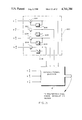
- FIG. 1 shows a block diagram of a transmitter of a modem of the present invention and the channel.
- FIG. 2A shows the upper two quadrants of the complex plane of the signal constellation used with the present invention.
- FIG. 2B shows the lower two quadrants of the complex plane of the signal constellation of the present invention.
- FIG. 3 shows a fragmented portion of the upper, right hand quadrant of the signal constellation and illustrates the distance properties in the constellation.
- FIG. 4 shows a data packet utilized in the present invention.
- FIG. 5 is a schematic diagram of a portion of the convolutional encoder which generates the subset-selecting bits.
- FIG. 6 shows a frame of the subset-selecting bits generated by the convolutional encoder.
- FIG. 7 shows the structure of the convolutional encoder.
- FIG. 8 shows two states of the trellis with the branches shown between the present state zero and the next state zero.
- FIG. 9 is a block diagram of the receiver of the present invention.
- FIG. 10 is a flow chart of the branch metric calculator of the present invention.
- FIG. 11 is a flow chart of the branch metric calculator of the present invention.
- FIG. 12 is a flow chart of the branch metric calculator of the present invention.
- FIG. 13 is a flow chart of the branch metric calculator of the present invention.
- FIG. 14 is a flow chart of the Viterbi decoder of the present invention.
- FIG. 15 is a schematic diagram of differential encoding for the convolutional encoder of FIG. 7.
- FIG. 16 is a schematic diagram of differential decoding for the convolutional decoder of FIG. 9.
- FIG. 1 there is shown a block diagram of the generalized structure of a transmitter 10 of a modem 12 in which the present invention is implemented.
- an information bit stream 14 is made up of serial digital data from a data source (not shown).
- bit sequences of fixed length are taken by a serial to parallel converter 16 to form packets of bits which are passed on to a convolutional encoder 18.
- a portion of the bits of each packet, symbol-selecting bits 20, are passed through the convolutional encoder 18 to a symbol generator 22.
- the remaining portion 24 of the bits of the packet are passed on to the convolutional encoder 18.
- the convolutional encoder 18 preferably, but not necessarily, is an encoder which allows for 2n dimensional coded modulation.
- a portion of the output of the convolutional encoder 18, i.e., subset-selecting bits 26, form a frame of an even number of bits, i.e, the subset-selection bits in a frame consist of 2n bits. In other implementations, the frame can have an odd number of bits.
- the subset-selecting bits 26 are passed to the symbol generator 22. For each received packet, the subset-selecting bits 26 and symbol-sselecting bits 20 form an output of the encoder 18 that will be identified as the expanded bit sequence.
- the symbol generator 22 typically uses a pair (i.e., bit group) of the 2n subset-selecting bits each baud (i.e., symbol interval/modulation period) to specify one of four subsets into which a symbol constellation is partitioned.
- the symbol-selecting bits 20 are used by the symbol generator 22 to select a symbol (i.e., signal point in constellation) from each subset. Consequently, each packet from the converter 16 is mapped onto a group of n 2-dimensional symbols in n bauds (one group interval), where n is >1 and defines a multidimensional point (symbol) 28.
- the multidimensional symbols 28, in a conventional manner, are filtered by bandwidth limiting filters and used to modulate a carrier in modulator and filter means 30 to provide a modulated carrier signal 32 to a band limited channel 34.
- the symbol generator 22 and modulator and filtering means 30 define a multidimensional coded modulation means 35.
- the modem 12 in which the present invention is preferably, but not necessarily, implemented transmits data at a rate of 19,200 bits per second.
- the symbol constellation 36 used by the symbol generator 22 of FIG. 1 is shown in FIGS. 2A and 2B, with upper two quadrants and lower two quadrants of the complex plane of the constellation 36 being shown, respectively, in FIGS. 2A and 2B.
- the transmitter 10 uses eight dimensional coded modulation.
- the baud rate is 2742.86 symbols per second with 7 bits per baud.
- the constellation 36 has 160 complex 2-dimensional symbols, i.e., signal points, with each symbol having a specific alphanumerical identifier.
- the symbols are divided into outer and inner points, with a circle around each signal point that is an outside point.
- the symbol constellation 36 also is divided into four subsets A0, A1, B0, B1, which are the first portion of the symbol identifier. After the subset identifier, separately for both inner or outer symbol groups, the symbols within each subset are designated in the symbol identifier by the number after the hyphen. For example, the symbol identifier "A0-5" for a circled point indicates an outer point from the subset A0, with that particular point being designated by number 5 within the outer points of the subset A0.
- the constellation is not only partitioned into four subsets of A0, A1, B0, and B1, but the constellation is also divided into a portion having inner points and a portion having outer points.
- the preferred embodiment has four subsets, different numbers and arrangements of subsets are possible.
- Each subset is represented by a two bit number shown in Table 1.
- the subset-selecting bits 26 of FIG. 1 form an output of the (m, m-1) convolutional encoder 18 of FIG. 1 which can be represented by n 2-dimensional subsets of the form shown in Table 1.
- the integer m is equal to 2n plus the number of symbol selecting bits.
- MSB and LSB stand for most significant bit and least significant bit, respectively.
- FIG. 3 To better illustrate the subset to symbol mapping provided by the symbol generator 22, a portion of the first quadrant of the symbol constellation 36 shown in FIG. 2A is enlarged and shown in FIG. 3.
- the symbols of the constellation 36 are on a square grid of the complex plane. From FIG. 3 it can be seen that the maximum Euclidean distance of 2 1/2 (d) occurs between A0 and A1 as well as between B0 and B1.
- the minimum distance of d is between A0 and B0, A0 and B1, A1 and B0 and A1 and B1.
- the maximum Hamming distance also occurs between A0 and A1, as well as between B0 and B1.
- FIG. 4 shows a packet of data generated by the serial to parallel converter 16 of FIG. 1 which comprises 28 bits which go to the convolutional encoder 18.
- the bits x 8 -x 28 are the symbol-selecting bits 20.
- bits x 1 , x 2 , x 3 , x 4 , x 5 , x 6 , and x 7 form the input bits 24 to convolutional encoder 18 of FIG. 1.
- FIGS. 1 , x 2 , x 3 , x 4 , x 5 , x 6 , and x 7 form the input bits 24 to convolutional encoder 18 of FIG. 1.
- bits y 7 , y 6 , y 5 , y 4 , y 3 , y 2 , y 1 , and y 0 of the encoder 18 are grouped into four bit groups (y 7 y 6 ), (y 5 y 4 ), (y 3 y 2 ) and (y 1 y 0 ) that defines a frame 48 of bits of FIG. 6.
- bits x 1 -x 7 form only a portion of the expanded bit sequence output of the encoder 18 of FIG. 1.
- FIGS. 5 and 6 shows the assignment of bit groups for each baud in the frame 48, with each bit group 50 defining a bit pair in the preferred embodiment.
- Each frame 48 has the duration of a group interval (time interval) that is four bauds in duration.
- each bit group 50 of FIG. 5 corresponds to one of the four 2-dimensional subsets A0, A1, B0 and B1.
- a symbol is transmitted from one of the 2-dimensional subsets in each of the four bauds.
- each frame 48 of FIG. 6 of eight bit output of the encoder 18 of FIG. 1 corresponds to one of 256 8 -dimensional symbol subsets, with each multidimensional symbol subset corresponding to a different combination of four 2-dimensional symbol subsets.
- the multidimensional symbol subset A1 B0 A0 B0 (11100010) corresponds to 2-dimensional symbol subsets (11), (10), (00) and (10).
- bit x 7 occurring in the nth frame will be referred to as x n 7 .
- Table 2 shows the assignment of points from inner and outer points of the constellation 36 shown in FIGS. 2A-2B for different values of x n 8 , x n 9 and x n 10 .
- Bit x n 8 indicates whether the frame 48 of FIG. 6 has any outer points or not.
- the dibit x n 9 x n 10 would indicate in which baud (and therefore bit group) the outer point would occur.
- "Inner” means inner point
- “Outer” means outer point.
- Table 3 shows how the symbol-selecting bits 20 of FIGS. 1 and 4 are assigned with each group of x n 8 , x n 9 , and x n 10 .
- FIG. 7 shows the convolutional encoder 18 of FIGS. 1 and 5 in detail.
- the encoder 18 is a 64 state (8, 7) encoder.
- the encoder adds one redundancy bit; however, in the preferred embodiment the encoder adds less than one bit per baud of redundancy into the system. Encoders with redundancies greater than one bit (and therefore redundancy of one or greater per baud) can be used with the present invention.
- Input bits x n 8 through x n 28 are passed through unchanged and unused to become output bits y n 8 though y n 28 .
- Inputs x n 4 -x n 7 are used but pass through the encoder 18 without being changed and become output bits y n 4 -y n 7 .
- the input bits x n 1 -x n 3 are expanded to create the output bits y n 0 -y n 3 .
- the output bits of y n 0 through y n 28 are identified as the expanded bit sequence, which includes the subset-selecting bits y n 0 -y n 7 and the symbol-selecting bits y n 8 -y.sub. n 28 .
- the convolutional encoder 18 includes four modulo 2 adders 52, 54, 56, and 58, each connected to receive at least some of the bits x n 3 , x n 2 , and x n 1 .
- the encoder 18 includes six delay elements 60, 62, 64, 66, 68, and 70, with each element providing a delay of one group interval (four bauds).
- the input bit x n 3 is fed to the modulo adders 52 and 58 via line 70a
- the input bit x n 2 is fed to the modulo adders 54 and 58 via line 70b
- the input bit x n 1 is fed to the modulo adders 56 and 58 via line 70c.
- the bit x n-1 3 is fed to the modulo adders 52 and 58 via line 70d
- the bit x n-1 2 is fed to the modulo adders 54 and 58 via line 70e
- the bit x n-1 1 is fed to the modulo adders 52, 54 and 56 via line 70f.
- the bit x n-2 3 is fed to the modulo adders 54 and 58 via line 70g
- the bit x n-2 2 is fed to the modulo adders 52 and 56 via line 70h
- the bit x n-2 1 is fed to the modulo adders 54 and 56 via line 70i.
- the bit x n 7 is fed to the modulo adders 52, 54, and 56 via line 70j.
- the bit x n 6 is fed to the modulo adders 52, 54, and 58 via line 70k.
- the 4 bit x n 5 is fed to the modulo adders 52, 56, and 58 via line 701.
- the bit x n 4 is fed to the modulo adders 54, 56 and 58 via line 70m.
- the input-output relationships of the subset-selecting bits 26 of the encoder 18 are as follows: ##EQU1## where D is a delay element and ⁇ + means an exclusive OR operation.
- the convolutional encoder 18 of FIG. 1 is a finite state device which passes through a succession of states, with each state being separated in time by one group interval. Referring to the trellis diagrams in FIG. 8, the encoder 18 of FIG. 1 has 64 possible states (not all shown). Due to the fact that the encoder 18 has three binary inputs, for a given present state, only 8 of the next states are permissible, i.e., can be reached from the present state. Which next state occurs is a function of the present state and on the combination of the x n 1 , x n 2 , and x n 3 bits received each group interval. Each permissible transition from one state to another state is identified by a coset of parallel branches.
- the trellis can be used to diagram all permissible transitions between the present state to the next state of the encoder, although only the parallel branches 74 between present state 0 and next state 0 are shown in FIG. 8.
- the branches from a present state to a next state can be either from one or the other group. Extending from the present state 0, 128 branches exist in the trellis 72, with 16 branches (one coset) going to each of 8 permissible next states (only one set of 16 is shown). Likewise, 128 branches can extend from each present state in the same manner and this is extended continuously between adjacent states separated by group intervals. In the preferred embodiment, the group used of the two groups of 128 branches alternates with the states, e.g., state 0 using one group and state 1 using the other group and so on.
- each branch is labeled by one of the 16 multidimensional symbol subsets of a given coset.
- 8 of the cosets are assigned to even number states and 8 are assigned to odd number states.
- the multidimensional symbol subsets associated with each branch can be indexed by integers ranging from 0 to 255. The index can be expressed as:
- Index of 8 dimensional subset 64(index of subset for baud 4)+16(index of subset for baud 3)+4(index of subset for baud 2)+index of subset for baud 1.
- the 2-dimensional subsets therein preferably, but not necessarily, are arranged as a frame of subsets for bauds 4, 3, 2, 1, in that order.
- the encoder 18 transmits 29 bits in 4 bauds or 7.25 bits per baud.
- a receiver 80 of the modem is generally shown in the block diagram of FIG. 9 and includes a demodulator 82.
- the noise affected modulated carrier signal is received over the channel 34 and in a conventional manner that will not be detailed herein is passed through the demodulator 82 (which is normally preceded by a Hilbert filter and passband equalizer) to produce a baseband signal consisting of a stream of received 2-dimensional symbol signals.
- the decoding process is repeated for each frame of received subset-defining bits (e.g., bits defining a multidimensional symbol subset), which is the received version of the frame transmitted and shown in FIG. 6.
- the receiver operation is synchronized to the frames of the incoming signal i.e., the receiver must know the beginning of each frame. In other words, the receiver must determine which bit group in the received frame of subset-defining bits corresponds to the bit group (y 1 y 0 ) in the transmitted subset-defining bits. Having found this starting bit group, the receiver frame of received subset-defining bits is synchronized with the transmitter frame of subset-defining bits.
- Each received multidimensional signal provides information in the form of the multidimensional subsets of the multidimensional points sent.
- the received 8-dimensionl signal can be decomposed into four 2-dimensional signals which occur consecutively. More specifically, each frame of the received multidimensional signal can be represented as R(1), R(2), R(3), and R(4), where:
- a symbol (ideal point) in the signal constellation can be represented as:
- N index of the point in the subset.
- the slicer 102 thus finds eight nearest points for the received signal of each baud. Of these eight ideal points, four are inner points and four are outer points. A pair of inner and outer points belong to each of the four subset A0, B0, B1 and A1. For each baud of the four baud frames, we can denote the Euclidean distance (metric) between each of the ideal point and the received point as d[J, K(J), L(J), N min (J)].
- the "K" terms are removed from the above equations, and the slider 102 thus finds the four nearest points to the received signal for each baud, regardless of whether the nearest point is an inner point or an outer point. Only the costs (metrics) of the four nearest points to the received signal are needed for the branch metric (cost) calculator 100 of the second embodiment and there is no need for keeping track of the points themselves.
- a branch metric (cost) is the distance between a received multidimensional signal and possible multidimensional symbol from the multidimensional symbol subset corresponding to the branch of the trellis.
- a Viterbi decoder (to be described hereinafter) computes a cumulative path metric for each of the survivor paths during each frame. This cumulative path metric (cost) is the arithmetic sum of the metrics of the individual branches which form the particular path.
- the branch metric calculator 100 selects for each coset (group of 16 parallel branches each) that branch, i.e., multidimensional symbol subset, which has the minimum branch metric, which results in reducing the number of contending branches from 256 to 16.
- each coset group of 16 parallel branches each
- multidimensional symbol subset which has the minimum branch metric, which results in reducing the number of contending branches from 256 to 16.
- only one branch of each coset can be a candidate to be part of one of the surviving paths of the trellis during the decoding process.
- the described reduction by a factor of 16 of the contending branches is based upon which branch of said coset represents the multidimensional symbol subset which is closest to the received multidimensional signal.
- the present invention concerns the computations performed by the branch cost calculator 100.
- the branch metric calculator 100 would compute the branch metric term, which can be either equal to or proportional to d BRANCH (I) where d BRANCH (I) is defined by:
- each branch of the trellis corresponds to a possible multidimensional symbol subset (therefore a four baud signal in the frame) and in this embodiment there are 256 branches, as identified by multidimensional symbol subsets A0 A0 A0 A0 through A1 A1 A1 A1.
- multidimensional symbol subset For each multidimensional symbol subset, five possible signal combinations of 2-dimensional symbols can be constructed having inner (In) and outer (Out) points (symbols) as shown in Table 4.
- the present invention is directed toward making it unnecessary to determine the branch metric for each branch and to directly compare all of the branch metrics (cost) during each group interval.
- the brute force approach can be avoided.
- the term "component” will be used in place of "2-dimensional symbol subset”.
- a branch is associated with a unique multidimensional symbol subset, which is a sequence of components and has n components.
- Each multidimensional symbol subset of a coset is defined as being a "member" of that coset.
- a submember of a member consists of part of the components of the member. The submember does not have all of the components of the member and only has components that form some part of the member in the same bauds. If two or more members (or submembers) have the same components for the same bauds, they are said to have common components, if not they are said to have non-common components in those bauds.
- the present invention makes use of the fact that several members have a common submember and the cost of this common submember (once calculated) can be used for all the members of any coset which has this common submember without having to be calculated repeatedly.
- FIG. 8 it is important to note that the parallel branches 74 between states are merely added to conceptually illustrate that when the convolutional encoder passes from one state to another, as shown by the lines connecting the states, one of a plurality of multidimensional symbol subsets have been generated. Of cource, the lines do not physically exist and what in fact exists is only a number representative of the multidimensional symbol subset.
- the 256 multidimensional symbol subsets (members) associated with 256 branches of the trellis for the encoder of FIG. 6 are provided in Table 5.
- the 256 multidimensional symbol subsets are tabulated into sixteen cosets, with there being 16 members for each coset.
- the left most component is that of the fourth baud, the next is that of third baud, the next is that of second baud and the right most is that of first baud.
- the order of the components within a given member are predetermined; however, it should be understood that this order can be reversed, i.e., the first component can be for the first baud and the last component for the fourth baud.
- the arrangement of cosets and the members in each coset brings out the commonality of the components.
- This commonality reduces the number of calculations needed to compute the value of the branch cost as given by Equation 6.
- use of this commonality reduces computations in two ways. First, it reduces the computations required to eliminate members within a coset. Second, costs calculated for one coset can be used in the other cosets.
- the preferred arrangement of the first embodiment of the present invention will be described, with the properties generated by such arrangements being also described.
- the cosets are grouped into four sets.
- the set of four cosets is identified as a supercoset.
- each coset is divided into four sets, with each set having four members. This set is identified as a subcoset.
- the members within a coset are arranged so that the four members of a subcoset have a property that the left most component is common for all.
- subcoset 1 belonging to coset 15 is as follows:
- the top most subcoset in each coset is identified as subcoset 1, with each one thereafter being progressively numbered until the bottom one, which is subcoset four.
- the four cosets which belong to the same supercoset have what is defined as a common three member property. This propery can be stated as follows. Any subcoset in a coset can be transformed to one of the subcoset in each of the other cosets belonging to the same supercoset by just changing the common components, i.e., the components within the same baud that are the same for all four members of the subcoset.
- belonging to coset 15 can be transformed to subcoset of coset 12.
- each subcoset there is commonality of two pairs of components in a second column. More particularly, for example, in coset 15, in the column for baud one, there are two common components of A1's and two common components of A0's. It is important to note that commonality is determined with reference to comparisons made between components of different members, not with components of the same member. Because each member has its components in a row, the commonality appears in the columns, although this could be reversed.
- each submember there are sixteen submembers containing the components for baud three and baud two, which can be split into eight sets of two submembers each.
- the component of each submember (consisting of two components) are the non-common components.
- the components of each submember are non-common components relative to the components of the other submember when a comparison is made between components of the two submembers of the same baud.
- Submember sets (1), (2), (3) and (4) of the first group are common to the supercoset 3 containing cosets 15, 12, 1 and 2, as well as to the supercoset 4 containing cosets 13, 14, 3 and 0.
- submember sets (5), (6), (7), and (8) of Group Two are common to supercoset 1 containing cosets 7, 4, 9, and 10 as well as supercoset 2 containing cosets 5, 6, 11 and 8.
- the subcosets in cosets 7, 4, 9, and 10 illustrate this point as follows in Table 7.
- each subcoset (two of the sets of Table 6) are common to the subcosets shown in Table 7. Additionally, the members of each subcoset are categorized into two pairs, with each pair having one of the sets. With respect only to the members of each pair of members, each submember forming part of the set is defined as the non-common portion of the member and the balance of each member that does not form part of the set is defined as the common portion of the member. In determining the member of each pair forming one of the sets with the minimum metric (cost), it can be determined by comparing only the summed costs of the two different components, thereby eliminating the need to sum the cost of all four components prior to comparing the cumulative metrics. Consequently, within each coset there are eight pairs of members having commonality, when compared with each other, in two common components. When further grouped into subcosets, each subcoset has common components for all members in one baud.
- the components for bauds three, two and one, which define four submembers are repeated four times. Therefore, the cost computations done for four submembers in one coset can be used for the submembers in three other cosets. Hence, the cost computation is reduced by a factor of four.
- the outer point occurs only in one baud of a multidimensional-symbol-subset.
- an algorithm to minimize the number of computations can be based on the following principle which we will denote as principle of algorithm one, which is used in the first embodiment.
- algorithm one as previously described, the slicer 102 of FIG. 9 computes the cost (metric or distance) of the nearest inner and outer point of each component (subset) to the received signal in each baud.
- the cost of baud three is added to baud two and the resulting cost is added to the cost of baud one and the second resulting cost is added to the cost of baud four.
- slicer 102 of FIG. 9 computes the distance of the received point from the closest inner and outer points for each component in each baud, as specified in Equations 3, 4 and 5.
- the determination is made as to whether the cost is smaller for the inner or outer point.
- the inner or outer point is chosen based upon whether inner cost is smaller or outer cost is smaller.
- the submember costs are calculated as follows. Referring to blocks 114, 116 and 118, if for any component in baud two, the minimum is for an outer point as determined at the block 114, then baud three is assumed to be an inner point at the block 118 and then for a submember containing that baud two component the cost of the inner point of the corresponding subset for baud three is added at the block 120. Otherwise, it is determined at the block 116 whether the inner or outer point of baud three has the minimum cost and at block 120 this minimum cost is added to the cost of the component at baud two. For example, for submember B0A0, component B0 represents baud three and component A0 represents baud two.
- the sixteen submembers (two components), as previously described, are separated into 8 set (pairs) of Table 6, at block 124.
- the cost for each has already been determined.
- the costs of each pair of compared and the surviving submember with the lowest cost is selected at block 126. Since these pairs of submembers are in every subcoset, comparing their cost to eliminate the submeber of higher cost thus reduces the total number of comparisons to be made.
- each of the two-component submembers for bauds three and two at block 132 a determination is made as to whether each two-component submember has an outer point in either component. If there is an outer point therein, then the component for baud one (as determined by a component counter) is assumed to be an inner point and one of four three-component members formed by use of the current two-component member is defined at block 136. If there is no outer point, then one of the four three-component members derived from a given two-component member is defined at block 138. Based upon the component values of 1, 2, 3, and 4, the baud one component added is A0, B1, B0 and A1, respectively, at the blocks 136 and 138.
- the costs of the inner and outer points for baud one are compared and the minimum cost component of the two is selected.
- the cost of the three-component submember is calculated at block 143 by adding the two-component member cost to the appropriate cost of the component for baud one.
- the component counter is incremented at block 144.
- each of the four components are used.
- Each of the four three-component submembers having as part thereof one of the eight two-component submembers is formed via loop 145. After all eight two-component submembers are processed through the loop 131, the program exits via decision block 146.
- the four three-component submembers of bauds three, two, and one found in each coset are repeated four times within a given supercoset.
- the four three-component submembers will be identified as a submember group. Consequently, within each supercoset, there are only four unique submember groups and among all the supercosets, there are 16 unique submember groups.
- the columns of submember groups are arranged in columns, going from left to right, from supercosets three, four, one, and two, respectively.
- the member of each subcoset with the least cost is formed by adding to the cost of the one surviving three-component submember to the cost of the corresponding component of baud four. At this point there is left four members and their associated cost for each coset, i.e., one for each subcoset. Three comparisons are made for each coset to obtain the minimum cost member for each coset with an allowable sequence.
- the rule is that, if the prior three-component submember contained an outer point as determined at block 154, then to the submember defined at block 156, the cost of the inner point for baud four is added at block 162. If there is no outer point, and for the member defined at block 156, the smaller cost of the two costs, one for the inner point and one for the outer point, is determined at block 150. As to the four-component members being defined in blocks 156 and 160, this is merely a matter of sequentially associating the baud four component (subset) to the appropriate submember.
- Each surviving three-component branch has the four components of baud four added thereo to generate the four members in four cosets of the same supercoset, as defined by the loops having blocks 164, 168 and 166. This is repeated for each surviving three-component submember as dictated by the loop having blocks 170 and 153. The cost of baud four is added to the three-component cost at block 162 and this is repeated for all 64 members.
- the branch metric calculator 100 of FIG. 9 does not take into account whether a point is an inner point or an outer point.
- a second algorithm is used which requires a lesser number of operations than algorithm one of the first embodiment and will be referred to as algorithm two.
- algorithm two no distinction is made between the cost of inner and outer points.
- the algorithm will now be described in detail and basically results in a simplified version of the first and has the following steps, with Tables 7 and 8 being again applicable. (1) For each baud, the cost of the closest point in each component (subset) to the received point in slicer 102 as previously described. (2).
- the cost of the component in baud two is added to the cost of the component in baud three to form sixteen costs for submembers with two-components.
- eight comparisons of the sixteen submembers are made, which leaves eight submembers. Each comparison involves a pair of submembers having the same common component in baud one.
- the cost of component of baud one is added to the cost of the surviving submembers. There are 32 additions and 32 new costs will be formed.
- Sixteen comparisons are made between pairs of three-component submembers of the same subcoset to come up with sixteen three-component member costs.
- the cost of the appropriate component in baud four is added to the three-component submember to form 64 costs of 64 branches. (7).
- the four costs in each coset are compared to find the lowest cost of each coset.
- the number of additions for algorithm two is the same as the number of additions for algorithm one.
- the number of comparisons for algorithm 2 is less than the number of comparisons for algorithm one by sixteen.
- the overall complexity of algorithm two is smaller than that of algorithm one.
- the slicer 102 of FIG. 9 for algorithm two has do half the number of computations as the slicer for algorithm one, since the former does not to search for inner and outer points separately.
- the members are needed during each addition. These members are tested to determine if the previous submember contains any outer point or not. Depending upon whether the previous submembers contained any outer point or not the subsequent instructions will have to be branched to the right location. This increases the number of instruction cycles needed to code the algorithm.
- the Viterbi decoder 104 for the first embodiment of the present invention in the receiver 80 uses the received multidimensional signals to estimate the original path of the encoder 18 through the trellis, such trellis being discussed with respect to FIG. 8.
- the maximum likelihood path is determined by finding the possible sequence of multidimensional symbol subsets (which trellis path) which is closest to the sequence of received multidimensional signals.
- the receiver computes the minimum cost path and from the path history, determines the estimated multidimensional symbol.
- the Viterbi decoder 104 during each frame (group interval) extends each of the surviving paths to their successor state at the next frame.
- the metric (cost) of the extended path is obtained by adding the metric of the survivor to the branch metric of the corresponding branch which extends the path.
- the survivor at the next frame at a given state is found by comparing the metrics of all the extended paths which connect to a given state and choosing the minimum.
- the path history of the surviving paths is extended.
- the decoder 104 finds the minimum cost path among the survivors, and from the path history outputs the best estimate of the multidimensional symbol subset for the group interval to a convolutional decoder 106.
- the delay between the present frame and the present estimate (of the past symbol) can be 3v frames, where v is the constraint length of the convolutional encoder 18 and in this case is 6.
- the convolutional decoder 106 From the retained knowledge of the received multidimensional signal sequence and from the knowledge of the closest multidimensional symbol subset of the maximum likelihood path, the best estimate of the transmitted multidimensional symbol (point) is obtained. From the estimated, transmitted multidimensional signal the convolutional decoder 106 produces the packet data. Finally a serial to parallel converter 108 converts this packet to serial data.
- the Viterbi decoder 104 of FIG. 9 for the second embodiment of the present invention is exactly the same conventional arrangement, except as follows. Once the minimum cost sequence is found and the corresponding member has been estimated at the receiver, it is necessary to determine (with knowledge of the corresponding received sequence, i.e., received multidimensional signal) which sequence of inner and outer points is closest to the received sequence which has just been estimated. As previously described and shown in Table 4, each member can be composed of five possible signal combinations of inner and outer points (2-dimensional symbols). The inner and outer points of the signal constellation are defined in Tables 2 and 3.
- the component costs of nearest ideal points can be used in the branch cost calculations (regardless of whether the nearest point is an inner or outer point) without significant loss in performance, if any resultant impermissible sequence of inner and outer signal points is corrected in the Viterbi decoder.
- the best estimate of a member which forms a part of the minimum cost path
- the received multidimensional signal i.e., multidimensional point (symbol) received
- the best estimate of the member i.e., a multidimensional symbol subset.
- the Viterbi decoder 104 calculates d BRANCH (I) of Equation 6 five times, one for each of the five combinations of Table 4.
- the "L” term is defined by the known member and the "K” term is defined by the particular sequence of inner and outer points. Consequently, there are five summed costs associated with the five combinations, and the combination with the minimum (smallest) summed cost is selected to be the multidimensional symbol provided to the convolutional decoder 106.
- the slicer output of the cost of the closest (in Euclidean distance) 2-dimensional symbol for each 2-dimensional symbol subset for each baud is used by the branch cost calculator.
- the slicer must provide for each best estimated member (multidimensional-symbol-subset) the cost of the closest inner point and outer point, but only for those 2-dimensional symbol subsets of the best estimated member. Referring to the flow chart of FIG. 16, this is done at block 182 for each best estimated member determined by the Viterbi decoder. Consequently, there are two 2-dimensional costs for each baud for a given best estimated member.
- five multidimensional symbols are selected from the best estimated multidimensional-symbol-subset (member) that have the sequences of inner and outer 2-dimensional symbols (components) shown in Table 4.
- the 2-dimensional cost provided above are summed to define a member (multidimensional cost), i.e. d BRANCH (I) of Equation 6, for each of the five multidimensional symbols.
- the multidimensional symbol with the minimum multidimensional cost (metric) is selected by the Viterbi decoder to be outputted to the convolutional decoder 106 and is defined as being the best estimated multidimensional symbol selected from the best estimated multidimensional-symbol-subset based upon the knowledge of the received multidimensional signal and the requirement of meeting one of the permissible sequences of Table 4.
- multidimensions shall mean more than 2-dimensions.
- the modem in which the present invention is implemented is a microprocessor based modem.
- the microprocessor-based modem control and data processing circuits also typically include the usual data storage element (e.g., ROM for program control storage and the like, and RAM for variable input/output/intermediate result data, etc.) conventionally associated with a microprocessor CPU for performing desired manipulation of digital signals in accordance with a stored program.
- data storage element e.g., ROM for program control storage and the like, and RAM for variable input/output/intermediate result data, etc.
- these already present microprocessor CPU, ROM and RAM elements are also utilized to perform the functions of the present invention.
- the modem functions are implemented in Texas Instrument's TMS 32020 processors. With respect to FIG.
- the transmitter modem functions therein are preferable, but not necessarily, performed by the digital signal processor.
- a D/A converter and antialasing filters are used.
- all of the receiver modem functions of FIG. 9 are preferably, but not necessarily, performed by the digital signal processor.
- the received signal is processed by an A/D converter and filters.
- Equation 1 the dependence of y n 3 , y n 2 , y n 1 and y n 0 on x n 7 , x n 6 , x n 5 and x n 4 in Equation 1 can be expressed by the vector: ##EQU3## where the first row corresponds to y n 3 , the second row to y n 2 , the third row to y n 1 and the fourth row to y n 0 . By interchanging the rows, a total of 24 different vectors can be obtained.
- the unchanged bits y n 4 through y n 28 are shown as being part of the inputs and outputs of the convolutional encoder, although they pass through the convolutional encoder unchanged and of that group only bits y n 4 through y n 7 are used by the encoder.
- the unchanged bits do not have to be considered as part of the convolutional encoder.
- the convolutional encoder outputs (y n 7 y n 6 y n 5 y n 4 y n 3 y n 2 y n 1 y n 0 ) satisfy the parity check equation:
- v is the constraint length of the encoder.
- the constraint length of the encoder is six, since there are six shift registers.
- the concept of the parity check equation and constraint length are well-known in the literature of convolutional codes as shown by U.S. Pat. No. 4,601,044 to Kromer et al.
- the parity check equation is given by ##EQU4##
- the total number of terms in the parity check equation is an even number.
- P is still zero, because of the even number of terms in the parity check equation.
- the received points are 180 degrees from the transmitted points. Under this condition, the received 2-dimensional subsets are changed as follows:
- the parity check equation P remains zero even though y n i goes to y n i . In other words, for all the various encoders, even with 180 degrees phase shift, the output sequence satisfies the parity check equation.
- the input to the convolutional encoder 18 of FIG. 1 can be differentially encoded by a differential encoder 200 as shown in FIG. 15, and the output to the convolutional decoder 106 of FIG. 9 can be differentially decoded by a differential decoder 202.
- this alternative embodiment is the same as the implementation shown in FIGS. 1 and 9.
- To differentially encode a sequence of bits x n-1 , x n , x n+1 . . . to a sequence of bits z n-1 , z n , z n+1 . . . the following operation is performed:
- Equation 12 From Equation 12 it can be seen that the sequence x n , x n+1 , . . . can be recovered from the sequence z n , z n+1 , . . . or the inverted sequence z n , z n+1 , . . .
- FIG. 7 illustrates one of these 24 possibilities. The other 23 possibilities would have the bits y n 4 through y n 7 of FIG. 7 connected to the modulo two adders in a manner dictated by Equation 8, with the remainder of the structure of the encoder remaining the same.
- x n 7 goes to x n 7
- x n 6 goes to x n 6
- x n 5 goes to x n 5
- x n 4 goes to x n 4
- x n 3 goes to x n 3
- x n 2 goes to x n 2
- x n 1 goes to x n 1 .
- differential encoder 200 takes x n 4 through x n 7 (the bits that are inverted in this example) and processes each through an Exclusive Or 204 and feedback loop with a delay element 206 of one group interval (labeled T F ) to perform the operation of Equation 11.
- the output bits (that can be inverted) of the convolutional decoder 106 are each differentially decoded by a feedforward loop with a delay element 208 of one group interval and an Exclusive Or 210.
Abstract
Description
m=pq
              TABLE 1
______________________________________
              Subset Index
Subset          MSB     LSB
______________________________________
A0              0       0
B1              0       1
B0              1       0
A1              1       1
______________________________________
              TABLE 2
______________________________________
x.sub.n.sup.8
      x.sub.n.sup.9
            x .sub.n.sup.10
                     baud 1 baud 2 baud 3 baud 4
______________________________________
0     X     X        Inner  Inner  Inner  Inner
1     0     0        Outer  Inner  Inner  Inner
1     0     1        Inner  Outer  Inner  Inner
1     1     0        Inner  Inner  Outer  Inner
1     1     1        Inner  Inner  Inner  Outer
______________________________________
              TABLE 3
______________________________________
x.sub.n.sup.8
      x.sub.n.sup.9
            x .sub.n.sup.10
                     baud 1
                           baud 2  baud 3
                                         baud 4
______________________________________
0     X     X        .sup. x.sub.n.sup.9 - x .sub.n.sup.13
                           x .sub.n.sup.14  - x .sub.n.sup.18
                                   x .sub.n.sup.19  - x .sub.n.sup. 23
                                         x .sub.n.sup.24  -
                                         x .sub.n.sup.28
1     0     0        x .sub.n.sup.11  - x .sub.n.sup.13
                           x .sub.n.sup.14  - x .sub.n.sup.18
                                   x .sub.n.sup.19  - x .sub.n.sup.23
                                         x .sub. n.sup.24  -
                                         x .sub.n.sup.8
1     0     1        x .sub.n.sup.11  - x .sub.n.sup.15
                           x .sub.n.sup.16  - x  .sub.n.sup.18
                                   x .sub.n.sup.19  - x .sub.n.sup.23
                                         x .sub. n.sup.24  -
                                         x .sub.n.sup.8
1     1     0        x .sub.n.sup.11  - x .sub.n.sup.15
                           x .sub.n.sup.16  - x .sub.n.sup.20
                                   x .sub.n.sup.21  - x .sub.n.sup.23
                                         x .sub. n.sup.24  -
                                         x .sub.n.sup.8
1     1     1        x .sub.n.sup.11  - x .sub.n.sup.15
                           x .sub.n.sup.16  - x .sub.n.sup.20
                                   x .sub.n.sup.21  - x .sub.n.sup.25
                                         x .sub. n.sup.26  -
                                         x .sub.n.sup.8
______________________________________
R(J)=[RX(J), RY(J)], 1<J<4 (Equation 2)
IDL(K, L, N)=[IDLX(K, L, N), IDLY(K, L, N)] (Equation 3)
|R(J)-IDL(K, L, N.sub.min)|<|R(J)-IDL(K, L, N)|
|R(J)-IDL(K, L, N)|.sup.2 =|RX(J)-IDLX(K, L, N)|.sup.2 +|RY(J)-IDLY(K, L, N)|.sup.2 (Equation 4)
d[J, K(J), L(J), N.sub.min (J)]=|R(J)=IDL[K(J), L(J), N.sub.min (J)]| (Equation 5)
d.sub.BRANCH (I)=[d.sup.2 (1, K(1), L(1), N.sub.min(1))+d.sup.2 (2, K(2), L(2), N.sub.min(2))+d.sup.2 (3, K(3), L(3), N.sub.min(3))+d.sup.2 (4, K(4),L(4), N.sub.min(4))] (Equation 6)
              TABLE 4
______________________________________
In          In         In         Out
In          In         Out        In
In          Out        In         In
Out         In         In         In
In          In         In         In
______________________________________
              TABLE 5
______________________________________
SUPERCOSET 1
Coset 7    Coset 4    Coset 9    Coset 10
______________________________________
A0A0B1A1   A0A0B1A0   A0A0B0B1   A0A0B0B0
A0B1A0A0   A0B1A0A1   A0B1A1B0   A0B1A1B1
A0B0A1A0   A0B0A1A1   A0B0A0B0   A0B0A0B1
A0A1B0A1   A0A1B0A0   A0A1B1B1   A0A1B1B0
B1A0B0B0   B1A0B0B1   B1A0B1A0   B1A0B1A1
B1B1A1B1   B1B1A1B0   B1B1A0A1   B1B1A0A0
B1B0A0B1   B1B0A0B0   B1B0A1A1   B1B0A1A0
B1A1B1B0   B1A1B1B1   B1A1B0A0   B1A1B0A1
B0A0B0B1   B0A0B0B0   B0A0B1A1   B0A0B1A0
B0B1A1B0   B0B1A1B1   B0B1A0A0   B0B1A0A1
B0B0A0B0   B0B0A0B1   B0B0A1A0   B0B0A1A1
B0A1B1B1   B0A1B1B0   B0A1B0A1   B0A1B0A0
A1A0B1A0   A1A0B1A1   A1A0B0B0   A1A0B0B1
A1B1A0A1   A1B1A0A0   A1B1A1B1   A1B1A1B0
A1B0A1A1   A1B0A1A0   A1B0A0B1   A1B0A0B0
A1A1B0A0   A1A1B0A1   A1A1B1B0   A1A1B1B1
______________________________________
SUPERCOSET 2
Coset 5    Coset 6    Coset 11   Coset 8
______________________________________
A0A0B1B1   A0A0B1B0   A0A0B0A1   A0A0B0A0
A0B1A0B0   A0B1A0B1   A0B1A1A0   A0B1A1A1
A0B0A1B0   A0B0A1B1   A0B0A0A0   A0B0A0A1
A0A1B0B1   A0A1B0B0   A0A1B1A1   A0A1B1A0
B1A0B0A0   B1A0B0A1   B1A0B1B0   B1A0B1B1
B1B1A1A1   B1B1A1A0   B1B1A0B1   B1B1A0B0
B1B0A0A1   B1B0A0A0   B1B0A1B1   B1B0A1B0
B1A1B1A0   B1A1B1A1   B1A1B0B0   B1A1B0B1
B0A0B0A1   B0A0B0A0   B0A0B1B1   B0A0B1B0
B0B1A1A0   B0B1A1A1   B0B1A0B0   B0B1A0B1
B0B0A0A0   B0B0A0A1   B0B0A1B0   B1B0A1B1
B0A1B1A1   B0A1B1A0   B0A1B0B1   B1A1B0B0
A1A0B1B0   A1A0B1B1   A1A0B0A0   A1A0B0A1
A1B1A0B1   A1B1A0B0   A1B1A1A1   A1B1A1A0
A1B0A1B1   A1B0A1B0   A1B0A0A1   A1B0A0A0
A1A1B0B0   A1A1B0B1   A1A1B1A0   A1A1B1A1
______________________________________
SUPERCOSET 3
Coset 15   Coset 12   Coset 1    Coset 2
______________________________________
A0A0A1A1   A0A0A1A0   A0A0A0B1   A0A0A0B0
A0B1B0A0   A0B1B0A1   A0B1B1B0   A0B1B1B1
A0B0B1A0   A0B0B1A1   A0B0B0B0   A0B0B0B1
A0A1A0A1   A0A1A0A0   A0A1A1B1   A0A1A1B0
B1A0A0B0   B1A0A0B1   B1A0A1A0   B1A0A1A1
B1B1B1B1   B1B1B1B0   B1B1B0A1   B1B1B0A0
B1B0B0B1   B1B0B0B0   B1B0B1A1   B1B0B1A0
B1A1A1B0   B1A1A1B1   B1A1A0A0   B1A1A0A1
B0A0A0B1   B0A0A0B0   B0A0A1A1   B0A0A1A0
B0B1B1B0   B0B1B1B1   B0B1B0A0   B0B1B0A1
B0B0B0B0   B0B0B0B1   B0B0B1A0   B0B0B1A1
B0A1A1B1   B0A1A1B0   B0A1A0A1   B0A1A0A0
A1A0A1A0   A1A0A1A1   A1A0A0B0   A1A0A0B1
A1B1B0A1   A1B1B0A0   A1B1B1B1   A1B1B1B0
A1B0B1A1   A1B0B1A0   A1B0B0B1   A1B0B0B0
A1A1A0A0   A1A1A0A1   A1A1A1B0   A1A1A1B1
______________________________________
SUPERCOSET 4
Coset 13   Coset 14   Coset 3    Coset 0
______________________________________
A0A0A1B1   A0A0A1B0   A0A0A0A1   A0A0A0A0
A0B1B0B0   A0B1B0B1   A0B1B1A0   A0B1B1A1
A0B0B1B0   A0B0B1B1   A0B0B0A0   A0B0B0A1
A0A1A0B1   A0A1A0B0   A0A1A1A1   A0A1A1A0
B1A0A0A0   B1A0A0A1   B1A0A1B0   B1A0A1B1
B1B1B1A1   B1B1B1A0   B1B1B0B1   B1B1B0B0
B1B0B0A1   B1B0B0A0   B1B0B1B1   B1B0B1B0
B1A1A1A0   B1A1A1A1   B1A1A0B0   B1A1A0B1
B0A0A0A1   B0A0A0A0   B0A0A1B1   B0A0A1B0
B0B1B1A0   B0B1B1A1   B0B1B0B0   B0B1B0B1
B0B0B0A0   B0B0B0A1   B0B0B1B0   B0B0B1B1
B0A1A1A1   B0A1A1A0   B0A1A0B1   B0A1A0B0
A1A0A1B0   A1A0A1B1   A1A0A0A0   A1A0A0A1
A1B1B0B1   A1B1B0B0   A1B1B1A1   A1B1B1A0
A1B0B1B1   A1B0B1B0   A1B0B0A1   A1B0B0A0
A1A1A0B0   A1A1A0B1   A1A1A1A0   A1A1A1A1
______________________________________
______________________________________
Fourth Baud
______________________________________
A0                   A0    A1    A1
A0                   B1    B0    A0
A0                   B0    B1    A0
A0                   A1    A0    A1
______________________________________
______________________________________
A0           A0         A1        A1
A0           B1         B0        A0
A0           B0         B1        A0
A0           A1         A0        A1
______________________________________
______________________________________
A1           A0         A1        A1
A1           B1         B0        A0
A1           B0         B1        A0
A1           A1         A0        A1
______________________________________
              TABLE 6
______________________________________
Baud Three
        Baud Two         Baud Three
                                  Baud Two
______________________________________
FIRST GROUP
A0      A1         (1)   A0       A0      (3)
A1      A0               A1       A1
B0      B1         (2)   B0       B0      (4)
B1      B0               B1       B1
SECOND GROUP
A0      B1         (5)   A0       B0      (7)
A1      B0               A1       B1
B0      A1         (6)   B0       A0      (8)
B1      A0               B1       A1
______________________________________
              TABLE 7
______________________________________
B0 A0B0
       B1    B0    A0B0  B0  A1  A0B0  B0  A1  A0B0  B1
B0 A1B1
       B1    B0    A1B1  B0  A1  A1B1  B0  A1  A1B1  B1
B0 B0A0
       B0    B0    B0A0  B1  A1  B0A0  B1  A1  B1A1  B0
B0 B1A1
       B0    B0    B1A1  B1  A1  B1A1  B1  A1  B0A0  B0
Coset 7  Coset 4     Coset 9     Coset 10
______________________________________
______________________________________
             A0  B0
             A1  B1
             B0  A0
             B1  A1
______________________________________
              TABLE 6
______________________________________
A0A0        A0B1       A0B0       A0A1
B1A0        B1B1       B1B0       B1A1
B0A0        B0B1       B0B0       B0A1
A1A0        A1B1       A1B0       A1A1
______________________________________
              TABLE 7
______________________________________
Minimum of (A0A0 and A1A1),
then add cost of [A0, B1, B0, and A1]
Minimum of (B1B1 and B0B0),
then add cost of [A0, B1, B0, and A1]
Minimum of (A0A1 and A1A0),
then add cost of [A0, B1, B0, and A1]
Minimum of (B0B1 and B1B0),
then add cost of [A0, B1, B0, and A1]
Minimum of (A0B0 and A1B1),
then add cost of [A0, B1, B0, and A1]
Minimum of (B1A1 and B0A0),
then add cost of [A0, B1, B0, and A1]
Minimum of (A0B1 and A1B0),
then add cost of [A0, B1, B0, and A1]
Minimum of (B1A0 and B0A1),
then add cost of [A0, B1, B0, and A1]
______________________________________
              TABLE 8
______________________________________
A0A1A1      A0A1B0     A0B1B0     A0B1A1
B1B0A0      B1B0B1     B1A0B1     B1A0A0
B0B1A0      B0B1B1     B0A1B1     B0A1A0
A1A0A1      A1A0B0     A1B0B0     A1B0A1
A0A0B0      A0A0A0     A0B0A0     A0B0B1
B1B1B1      B1B1A1     B1A1A1     B1A1B0
B0B0B1      B0B0A1     B0A0A1     B0A0B0
A1A1B0      A1A1A0     A1B1A0     A1B1B1
A0A0B1      A0A0A1     A0B0A1     A0B0B0
B1B1B0      B1B1A0     B1A1A0     B1A1B1
B0B0B0      B0B0A0     B0A0A0     B0A0B1
A1A1B1      A1A1A1     A1B1A1     A1B1B0
A0A1A0      A0A1B1     A0B1B1     A0B1A0
B1B0A1      B1B0B0     B1A0B0     B1A0A1
B0B1A1      B0B1B0     B0A1B0     B0A1A1
A1A0A0      A1A0B1     A1B0B1     A1B0A0
______________________________________
              TABLE 9
______________________________________
Operation            Addition Comparison
______________________________________
1.  If for baud two the  16       8
    inner point is chosen
    then add cost of baud
    two to minimum of (inner
    cost, outer cost) of
    baud three; else add cost
    of baud two to cost of
    inner point of baud three.
2.  Subdivide the sixteen         8
    two components to eight
    components of two each and
    choose the minimum in
    each component.
3.  If either baud two or baud
                         32       4
    three contains no outer
    point then add minimum of
    (inner cost, outer cost) of
    baud one to the combined
    costs of bauds two and three;
    else add the inner cost of
    baud one to combined costs of
    bauds two and three.
4.  Divide the 32 members         16
    into 16 components and compare
    the cost in each component.
5.  If either baud one, two or
                         64       4
    three contains no outer point
    then add minimum of (inner
    cost, outer cost) for baud
    four, else add inner cost
    for baud four.
6.  Compare the four members      48
    in each coset to choose the
    minimum cost in each coset.
    TOTALS               112      88
______________________________________
yH.sup.T =0 (Equation 9)
y=(y.sub.n.sup.7 y.sub.n.sup.6 y.sub.n.sup.5 y.sub.n.sup.4 y.sub.n.sup.3 y.sub.n.sup.2 y.sub.n.sup.1 y.sub.n.sup.0)
H=(H.sup.8 (D)H.sup.7 (D)H.sup.6 (D)H.sup.5 (D)H.sup.4 (D)H.sup.3 (D)H.sup.2 (D)H.sup.1 (D)H.sup.0 (D)
H.sup.i (D)=a.sub.v D.sup.v ⊕a.sub.v-1 D.sup.v-1 ⊕0 . . . a.sub.0
(y.sub.n.sup.2k-1 y.sub.n.sup.2k-2) goes to (y.sub.n.sup.2k-1 y.sub.n.sup.2k-2)
z.sub.n =z.sub.n-1 ⊕x.sub.n (Equation 11)
x.sub.n =z.sub.n ⊕z.sub.n-1 (Equation 12)
Claims (53)
Priority Applications (6)
| Application Number | Priority Date | Filing Date | Title |
|---|---|---|---|
| US07/004,389 US4761784A (en) | 1987-01-15 | 1987-01-15 | Modem and method using multidimensional coded modulation |
| JP63501077A JPH02504690A (en) | 1987-01-15 | 1987-12-16 | Modem and method using multidimensional code modulation |
| DE3751039T DE3751039T2 (en) | 1987-01-15 | 1987-12-16 | MODEM AND METHOD FOR USING MULTI-DIMENSIONAL CODED MODULATION. |
| PCT/US1987/003356 WO1988005571A1 (en) | 1987-01-15 | 1987-12-16 | Modem and method using multidimensional coded modulation |
| EP88900914A EP0341256B1 (en) | 1987-01-15 | 1987-12-16 | Modem and method using multidimensional coded modulation |
| CA000556101A CA1295741C (en) | 1987-01-15 | 1988-01-08 | Modem and method using multidimensional coded modulation |
Applications Claiming Priority (1)
| Application Number | Priority Date | Filing Date | Title |
|---|---|---|---|
| US07/004,389 US4761784A (en) | 1987-01-15 | 1987-01-15 | Modem and method using multidimensional coded modulation |
Publications (1)
| Publication Number | Publication Date |
|---|---|
| US4761784A true US4761784A (en) | 1988-08-02 |
Family
ID=21710565
Family Applications (1)
| Application Number | Title | Priority Date | Filing Date |
|---|---|---|---|
| US07/004,389 Expired - Lifetime US4761784A (en) | 1987-01-15 | 1987-01-15 | Modem and method using multidimensional coded modulation |
Country Status (6)
| Country | Link |
|---|---|
| US (1) | US4761784A (en) |
| EP (1) | EP0341256B1 (en) |
| JP (1) | JPH02504690A (en) |
| CA (1) | CA1295741C (en) |
| DE (1) | DE3751039T2 (en) |
| WO (1) | WO1988005571A1 (en) |
Cited By (26)
| Publication number | Priority date | Publication date | Assignee | Title |
|---|---|---|---|---|
| US4809277A (en) * | 1986-10-14 | 1989-02-28 | Nec Corporation | Convolutional encoder |
| US4809300A (en) * | 1988-04-05 | 1989-02-28 | General Datacomm, Inc. | Branch metric algorithm for eight-dimensional signal constellation |
| US5113401A (en) * | 1989-07-07 | 1992-05-12 | International Business Machines Corporation | Block coding scheme for fractional-bit transmission |
| US5119403A (en) * | 1991-04-09 | 1992-06-02 | Racal Data Communications Inc. | Superframes |
| US5181209A (en) * | 1989-04-03 | 1993-01-19 | Deutsche Forschungsanstalt Fur Luft- Und Raumfahrt E.V. | Method for generalizing the viterbi algorithm and devices for executing the method |
| US5185763A (en) * | 1991-04-09 | 1993-02-09 | Racal-Datacom, Inc. | Data bit to constellation symbol mapper |
| US5243605A (en) * | 1991-07-11 | 1993-09-07 | Storage Technology Corporation | Modified viterbi detector with run-length code constraint |
| US5263052A (en) * | 1991-09-30 | 1993-11-16 | Motorola, Inc. | Viterbi equalizer for radio receiver |
| US5675139A (en) * | 1995-05-18 | 1997-10-07 | Symbol Technologies, Inc. | Interface arrangement for use with consumer devices |
| US5754600A (en) * | 1994-08-29 | 1998-05-19 | Motorola, Inc. | Method and apparatus for optimum soft-decision viterbi decoding of convolutional-differential encoded QPSK data in coherent detection |
| US5841796A (en) * | 1995-03-14 | 1998-11-24 | Comsat Corporation | Apparatus and method for calculating viterbi path metric using exponentially-weighted moving average |
| US20030169830A1 (en) * | 2002-03-06 | 2003-09-11 | Nokia Corporation | Method and apparatus for modulation using an at least four-dimensional signal constellation |
| US6654928B1 (en) * | 2000-07-20 | 2003-11-25 | Nokia Mobile Phones Limited | Hybrid dimensional, spherical space-time coding and decoding apparatus, and associated method, for a communication system |
| US6760385B1 (en) * | 2000-05-30 | 2004-07-06 | Adtran, Inc. | Universal parallel processing decoder |
| US20040181419A1 (en) * | 2003-03-15 | 2004-09-16 | Davis Linda Mary | Spherical decoder for wireless communications |
| US7254167B2 (en) | 1998-10-30 | 2007-08-07 | Broadcom Corporation | Constellation-multiplexed transmitter and receiver |
| US20070230641A1 (en) * | 2006-03-29 | 2007-10-04 | Provigent Ltd. | Adaptive receiver loops with weighted decision-directed error |
| US20080130726A1 (en) * | 2006-12-05 | 2008-06-05 | Provigent Ltd. | Data rate coordination in protected variable-rate links |
| US20080254749A1 (en) * | 2007-04-13 | 2008-10-16 | Provigent Ltd. | Management of variable-rate communication links |
| US20080259901A1 (en) * | 2007-04-20 | 2008-10-23 | Provigent, Ltd. | Adaptive coding and modulation for synchronous connections |
| US20090049361A1 (en) * | 2007-08-13 | 2009-02-19 | Provigent Ltd | Protected communication link with improved protection indication |
| US20090092208A1 (en) * | 2007-10-09 | 2009-04-09 | Provigent Ltd | Decoding of forward error correction codes in the presence of phase noise |
| US7613260B2 (en) | 2005-11-21 | 2009-11-03 | Provigent Ltd | Modem control using cross-polarization interference estimation |
| US7643512B2 (en) | 2006-06-29 | 2010-01-05 | Provigent Ltd. | Cascaded links with adaptive coding and modulation |
| US20100018780A1 (en) * | 2008-07-25 | 2010-01-28 | Smith International, Inc. | Pdc bit having split blades |
| US7720136B2 (en) | 2006-12-26 | 2010-05-18 | Provigent Ltd | Adaptive coding and modulation based on link performance prediction |
Citations (7)
| Publication number | Priority date | Publication date | Assignee | Title |
|---|---|---|---|---|
| US4077021A (en) * | 1976-06-18 | 1978-02-28 | International Business Machines Corporation | Method and arrangement for coding binary signals and modulating a carrier signal |
| US4457004A (en) * | 1982-02-08 | 1984-06-26 | Bell Telephone Laboratories, Incorporated | Multidimensional channel coding |
| EP0154415A1 (en) * | 1984-02-06 | 1985-09-11 | Codex Corporation | Coded modulation system |
| US4581601A (en) * | 1984-06-25 | 1986-04-08 | At&T Bell Laboratories | Multi-dimensional coding for error reduction |
| US4597090A (en) * | 1983-04-14 | 1986-06-24 | Codex Corporation | Block coded modulation system |
| EP0200505A2 (en) * | 1985-04-25 | 1986-11-05 | Codex Corporation | Apparatus for transmitting streams of information bits and methods for estimating the most likely sequence sent |
| US4709377A (en) * | 1985-03-13 | 1987-11-24 | Paradyne | Viterbi decoder for wireline modems |
-
1987
- 1987-01-15 US US07/004,389 patent/US4761784A/en not_active Expired - Lifetime
- 1987-12-16 EP EP88900914A patent/EP0341256B1/en not_active Expired - Lifetime
- 1987-12-16 WO PCT/US1987/003356 patent/WO1988005571A1/en active IP Right Grant
- 1987-12-16 DE DE3751039T patent/DE3751039T2/en not_active Expired - Fee Related
- 1987-12-16 JP JP63501077A patent/JPH02504690A/en active Pending
-
1988
- 1988-01-08 CA CA000556101A patent/CA1295741C/en not_active Expired - Fee Related
Patent Citations (8)
| Publication number | Priority date | Publication date | Assignee | Title |
|---|---|---|---|---|
| US4077021A (en) * | 1976-06-18 | 1978-02-28 | International Business Machines Corporation | Method and arrangement for coding binary signals and modulating a carrier signal |
| US4457004A (en) * | 1982-02-08 | 1984-06-26 | Bell Telephone Laboratories, Incorporated | Multidimensional channel coding |
| US4597090A (en) * | 1983-04-14 | 1986-06-24 | Codex Corporation | Block coded modulation system |
| EP0154415A1 (en) * | 1984-02-06 | 1985-09-11 | Codex Corporation | Coded modulation system |
| US4700349A (en) * | 1984-02-06 | 1987-10-13 | Codex Corporation | Coded modulation system |
| US4581601A (en) * | 1984-06-25 | 1986-04-08 | At&T Bell Laboratories | Multi-dimensional coding for error reduction |
| US4709377A (en) * | 1985-03-13 | 1987-11-24 | Paradyne | Viterbi decoder for wireline modems |
| EP0200505A2 (en) * | 1985-04-25 | 1986-11-05 | Codex Corporation | Apparatus for transmitting streams of information bits and methods for estimating the most likely sequence sent |
Non-Patent Citations (2)
| Title |
|---|
| Forney, David G. et al., "Efficient Modulation for Band Limited Channels", IEEE Journal on Selected Areas in Communication, vol. SAC, Sep. 2, 1984, pp. 632-645. |
| Forney, David G. et al., Efficient Modulation for Band Limited Channels , IEEE Journal on Selected Areas in Communication, vol. SAC, Sep. 2, 1984, pp. 632 645. * |
Cited By (41)
| Publication number | Priority date | Publication date | Assignee | Title |
|---|---|---|---|---|
| US4809277A (en) * | 1986-10-14 | 1989-02-28 | Nec Corporation | Convolutional encoder |
| US4809300A (en) * | 1988-04-05 | 1989-02-28 | General Datacomm, Inc. | Branch metric algorithm for eight-dimensional signal constellation |
| US5181209A (en) * | 1989-04-03 | 1993-01-19 | Deutsche Forschungsanstalt Fur Luft- Und Raumfahrt E.V. | Method for generalizing the viterbi algorithm and devices for executing the method |
| US5113401A (en) * | 1989-07-07 | 1992-05-12 | International Business Machines Corporation | Block coding scheme for fractional-bit transmission |
| US5119403A (en) * | 1991-04-09 | 1992-06-02 | Racal Data Communications Inc. | Superframes |
| US5185763A (en) * | 1991-04-09 | 1993-02-09 | Racal-Datacom, Inc. | Data bit to constellation symbol mapper |
| US5243605A (en) * | 1991-07-11 | 1993-09-07 | Storage Technology Corporation | Modified viterbi detector with run-length code constraint |
| US5263052A (en) * | 1991-09-30 | 1993-11-16 | Motorola, Inc. | Viterbi equalizer for radio receiver |
| US5754600A (en) * | 1994-08-29 | 1998-05-19 | Motorola, Inc. | Method and apparatus for optimum soft-decision viterbi decoding of convolutional-differential encoded QPSK data in coherent detection |
| US5841796A (en) * | 1995-03-14 | 1998-11-24 | Comsat Corporation | Apparatus and method for calculating viterbi path metric using exponentially-weighted moving average |
| US5675139A (en) * | 1995-05-18 | 1997-10-07 | Symbol Technologies, Inc. | Interface arrangement for use with consumer devices |
| US7254167B2 (en) | 1998-10-30 | 2007-08-07 | Broadcom Corporation | Constellation-multiplexed transmitter and receiver |
| US8462837B2 (en) | 1998-10-30 | 2013-06-11 | Broadcom Corporation | Constellation-multiplexed transmitter and receiver |
| US6760385B1 (en) * | 2000-05-30 | 2004-07-06 | Adtran, Inc. | Universal parallel processing decoder |
| US6654928B1 (en) * | 2000-07-20 | 2003-11-25 | Nokia Mobile Phones Limited | Hybrid dimensional, spherical space-time coding and decoding apparatus, and associated method, for a communication system |
| US20030169830A1 (en) * | 2002-03-06 | 2003-09-11 | Nokia Corporation | Method and apparatus for modulation using an at least four-dimensional signal constellation |
| US7230993B2 (en) * | 2002-03-06 | 2007-06-12 | Nokia Corporation | Method and apparatus for modulation using an at least four-dimensional signal constellation |
| US20040181419A1 (en) * | 2003-03-15 | 2004-09-16 | Davis Linda Mary | Spherical decoder for wireless communications |
| US7822150B2 (en) * | 2003-03-15 | 2010-10-26 | Alcatel-Lucent Usa Inc. | Spherical decoder for wireless communications |
| US7613260B2 (en) | 2005-11-21 | 2009-11-03 | Provigent Ltd | Modem control using cross-polarization interference estimation |
| US7796708B2 (en) | 2006-03-29 | 2010-09-14 | Provigent Ltd. | Adaptive receiver loops with weighted decision-directed error |
| US20070230641A1 (en) * | 2006-03-29 | 2007-10-04 | Provigent Ltd. | Adaptive receiver loops with weighted decision-directed error |
| US7643512B2 (en) | 2006-06-29 | 2010-01-05 | Provigent Ltd. | Cascaded links with adaptive coding and modulation |
| US7839952B2 (en) | 2006-12-05 | 2010-11-23 | Provigent Ltd | Data rate coordination in protected variable-rate links |
| US20080130726A1 (en) * | 2006-12-05 | 2008-06-05 | Provigent Ltd. | Data rate coordination in protected variable-rate links |
| US7720136B2 (en) | 2006-12-26 | 2010-05-18 | Provigent Ltd | Adaptive coding and modulation based on link performance prediction |
| US8315574B2 (en) | 2007-04-13 | 2012-11-20 | Broadcom Corporation | Management of variable-rate communication links |
| US8364179B2 (en) | 2007-04-13 | 2013-01-29 | Provigent Ltd. | Feedback-based management of variable-rate communication links |
| US8385839B2 (en) | 2007-04-13 | 2013-02-26 | Provigent Ltd. | Message-based management of variable-rate communication links |
| US20100185918A1 (en) * | 2007-04-13 | 2010-07-22 | Provigent Ltd | Message-based management of variable-rate communication links |
| US20080254749A1 (en) * | 2007-04-13 | 2008-10-16 | Provigent Ltd. | Management of variable-rate communication links |
| US20080259901A1 (en) * | 2007-04-20 | 2008-10-23 | Provigent, Ltd. | Adaptive coding and modulation for synchronous connections |
| US7821938B2 (en) | 2007-04-20 | 2010-10-26 | Provigent Ltd. | Adaptive coding and modulation for synchronous connections |
| US20090049361A1 (en) * | 2007-08-13 | 2009-02-19 | Provigent Ltd | Protected communication link with improved protection indication |
| US8001445B2 (en) | 2007-08-13 | 2011-08-16 | Provigent Ltd. | Protected communication link with improved protection indication |
| US8040985B2 (en) | 2007-10-09 | 2011-10-18 | Provigent Ltd | Decoding of forward error correction codes in the presence of phase noise |
| WO2009047755A3 (en) * | 2007-10-09 | 2010-03-04 | Provigent Ltd. | Decoding of forward error correction codes in the presence of phase noise |
| US8351552B2 (en) | 2007-10-09 | 2013-01-08 | Provigent Ltd. | Decoding of forward error correction codes in the presence of phase noise and thermal noise |
| WO2009047755A2 (en) * | 2007-10-09 | 2009-04-16 | Provigent Ltd. | Decoding of forward error correction codes in the presence of phase noise |
| US20090092208A1 (en) * | 2007-10-09 | 2009-04-09 | Provigent Ltd | Decoding of forward error correction codes in the presence of phase noise |
| US20100018780A1 (en) * | 2008-07-25 | 2010-01-28 | Smith International, Inc. | Pdc bit having split blades |
Also Published As
| Publication number | Publication date |
|---|---|
| DE3751039D1 (en) | 1995-03-16 |
| DE3751039T2 (en) | 1995-05-24 |
| CA1295741C (en) | 1992-02-11 |
| EP0341256B1 (en) | 1995-02-01 |
| JPH02504690A (en) | 1990-12-27 |
| EP0341256A1 (en) | 1989-11-15 |
| EP0341256A4 (en) | 1991-09-11 |
| WO1988005571A1 (en) | 1988-07-28 |
Similar Documents
| Publication | Publication Date | Title |
|---|---|---|
| US4761784A (en) | Modem and method using multidimensional coded modulation | |
| US4748626A (en) | Viterbi decoder with reduced number of data move operations | |
| US4807230A (en) | Frame synchronization | |
| Calderbank | Multilevel codes and multistage decoding | |
| EP0237186B1 (en) | Decoding of lattices and codes | |
| US4597090A (en) | Block coded modulation system | |
| KR100262426B1 (en) | Transmitter, receiver and multilevel coding modulation method | |
| CA1239479A (en) | Coded modulation system | |
| US5539757A (en) | Error correction systems with modified Viterbi decoding | |
| US4583236A (en) | Modified absolute phase detector | |
| EP0200505A2 (en) | Apparatus for transmitting streams of information bits and methods for estimating the most likely sequence sent | |
| EP1031218B1 (en) | Time-varying trellis coded psk | |
| JPH028503B2 (en) | ||
| US7224743B2 (en) | Efficient decoding of trellis coded modulation waveforms | |
| CN1162873A (en) | Viterbi decoder | |
| US4755998A (en) | Coded modulation system | |
| US5594742A (en) | Bidirectional trellis coding | |
| EP0287586B1 (en) | Data transmission system and method for use therein | |
| JPH06338808A (en) | Addition comparison selector | |
| Pottie et al. | An approach to ungerboeck coding for rectangular signal sets (Corresp.) | |
| US7031408B2 (en) | Mechanism for reducing recovery time after path loss in coded data communication system having sequential decoder | |
| WO2002015411A2 (en) | Unified technique for multi-rate trellis coding and decoding | |
| JP3348303B2 (en) | Viterbi decoding method and device | |
| JPH0214622A (en) | Maximum likelihood decoding method | |
| JPH0818617A (en) | Multilevel encoding modulation system and decoding system therefor |
Legal Events
| Date | Code | Title | Description |
|---|---|---|---|
| AS | Assignment |
Owner name: RACAL DATA COMMUNICATIONS INC., 1601 N. HARRISON P Free format text: ASSIGNMENT OF ASSIGNORS INTEREST.;ASSIGNORS:SRINIVASAGOPALAN, RANGARAJAN;PRUETT, JAMES D.;KRISHNAN, VEDAVALLI G.;AND OTHERS;REEL/FRAME:004666/0277 Effective date: 19870114 |
|
| STCF | Information on status: patent grant |
Free format text: PATENTED CASE |
|
| FEPP | Fee payment procedure |
Free format text: PAYOR NUMBER ASSIGNED (ORIGINAL EVENT CODE: ASPN); ENTITY STATUS OF PATENT OWNER: LARGE ENTITY |
|
| FPAY | Fee payment |
Year of fee payment: 4 |
|
| AS | Assignment |
Owner name: RACAL-DATACOM, INC., FLORIDA Free format text: ASSIGNMENT OF ASSIGNORS INTEREST;ASSIGNOR:RACAL-DATA COMMUNCIATIONS INC.;REEL/FRAME:007722/0734 Effective date: 19910820 |
|
| FPAY | Fee payment |
Year of fee payment: 8 |
|
| AS | Assignment |
Owner name: PEH WORLDWIDE HOLDING, LLC, A DELAWARE LIMITED LIA Free format text: SECURITY AGREEMENT;ASSIGNOR:RACAL-DATACOM, INC., A DELAWARE CORPORATION;REEL/FRAME:009500/0081 Effective date: 19980911 |
|
| AS | Assignment |
Owner name: FOOTHILL CAPITAL CORPORATION, CALIFORNIA Free format text: SECURITY INTEREST;ASSIGNOR:RACAL- DATACOM, INC., A DELAWARE CORPORATION;REEL/FRAME:009525/0011 Effective date: 19980911 |
|
| FPAY | Fee payment |
Year of fee payment: 12 |
|
| AS | Assignment |
Owner name: FOOTHILL CAPITAL CORPORATION, AS AGENT, CALIFORNIA Free format text: AMENDMENT TO PATENT SECURITY AGREEMENT;ASSIGNOR:MILGO SOLUTIONS, LLC;REEL/FRAME:011700/0287 Effective date: 20010402 Owner name: FOOTHILL CAPITAL CORPORATION, AS AGENT, CALIFORNIA Free format text: SECURITY AGREEMENT;ASSIGNORS:DATA COMMUNICATIONS 2000, INC.;MILGO SOLUTIONS, LLC, A DELAWARE LIMITED LIABILITY COMPANY;MILGO HOLDINGS CANADA, LLC, A DELAWARE LIMITED LIABILITY COMPANY;AND OTHERS;REEL/FRAME:011742/0104 Effective date: 20010402 |
|
| AS | Assignment |
Owner name: FOOTHILL CAPITAL CORPORATION, CALIFORNIA Free format text: AMENDED & RESTATED GUARANTOR PATENT SECURITY AGREEMENT;ASSIGNORS:DATA COMMUNICATIONS 2000, INC., A CALIFORNIA CORPORATION;NEXTIRAONE SOLUTIONS, LLC A DELAWARE LIMITED LIABILITY COMPANY;MILGO HOLDINGS CANADA, LLC A DELAWARE LIMITED LIABILITY COMPANY;AND OTHERS;REEL/FRAME:013240/0185 Effective date: 20020903 |
|
| AS | Assignment |
Owner name: MILGO HOLDINGS CANADA, LLC, TEXAS Free format text: RELEASE OF SECURITY INTEREST IN PATENT COLLATERAL;ASSIGNOR:WELLS FARGO FOOTHILL, INC. (F/K/A FOOTHILL CAPITAL CORPORATION), AS AGENT;REEL/FRAME:017336/0767 Effective date: 20060321 Owner name: NEXTIRAONE SOLUTIONS, LLC, TEXAS Free format text: RELEASE OF SECURITY INTEREST IN PATENT COLLATERAL;ASSIGNOR:WELLS FARGO FOOTHILL, INC. (F/K/A FOOTHILL CAPITAL CORPORATION), AS AGENT;REEL/FRAME:017336/0767 Effective date: 20060321 Owner name: DATA COMMUNICATIONS 2000, INC., TEXAS Free format text: RELEASE OF SECURITY INTEREST IN PATENT COLLATERAL;ASSIGNOR:WELLS FARGO FOOTHILL, INC. (F/K/A FOOTHILL CAPITAL CORPORATION), AS AGENT;REEL/FRAME:017336/0767 Effective date: 20060321 Owner name: TIMEPLEX, LLC, TEXAS Free format text: RELEASE OF SECURITY INTEREST IN PATENT COLLATERAL;ASSIGNOR:WELLS FARGO FOOTHILL, INC. (F/K/A FOOTHILL CAPITAL CORPORATION), AS AGENT;REEL/FRAME:017336/0767 Effective date: 20060321 Owner name: NEXTIRAONE CALIFORNIA, L.P., TEXAS Free format text: RELEASE OF SECURITY INTEREST IN PATENT COLLATERAL;ASSIGNOR:WELLS FARGO FOOTHILL, INC. (F/K/A FOOTHILL CAPITAL CORPORATION), AS AGENT;REEL/FRAME:017336/0767 Effective date: 20060321 Owner name: NEXTIRAONE NEW YORK, LLC, TEXAS Free format text: RELEASE OF SECURITY INTEREST IN PATENT COLLATERAL;ASSIGNOR:WELLS FARGO FOOTHILL, INC. (F/K/A FOOTHILL CAPITAL CORPORATION), AS AGENT;REEL/FRAME:017336/0767 Effective date: 20060321 Owner name: NEXTIRAONE FEDERAL, LLC, TEXAS Free format text: RELEASE OF SECURITY INTEREST IN PATENT COLLATERAL;ASSIGNOR:WELLS FARGO FOOTHILL, INC. (F/K/A FOOTHILL CAPITAL CORPORATION), AS AGENT;REEL/FRAME:017336/0767 Effective date: 20060321 Owner name: NEXTIRAONE CANADA ULC, TEXAS Free format text: RELEASE OF SECURITY INTEREST IN PATENT COLLATERAL;ASSIGNOR:WELLS FARGO FOOTHILL, INC. (F/K/A FOOTHILL CAPITAL CORPORATION), AS AGENT;REEL/FRAME:017336/0767 Effective date: 20060321 Owner name: NEXTIRAONE LLC (F/K/A WCS ACQUISITION II, LLC), TE Free format text: RELEASE OF SECURITY INTEREST IN PATENT COLLATERAL;ASSIGNOR:WELLS FARGO FOOTHILL, INC. (F/K/A FOOTHILL CAPITAL CORPORATION), AS AGENT;REEL/FRAME:017336/0767 Effective date: 20060321 |
|
| AS | Assignment |
Owner name: NEXTIRAONE SOLUTIONS, LLC, TEXAS Free format text: RELEASE OF SECURITY INTEREST IN PATENT COLLATERAL;ASSIGNOR:WELLS FARGO FOOTHILL, INC., AS AGENT, FORMERLY FOOTHILL CAPITAL CORPORATION;REEL/FRAME:017507/0866 Effective date: 20050613 |