US4760385A - Electronic mosaic imaging process - Google Patents
Electronic mosaic imaging process Download PDFInfo
- Publication number
- US4760385A US4760385A US06/879,443 US87944386A US4760385A US 4760385 A US4760385 A US 4760385A US 87944386 A US87944386 A US 87944386A US 4760385 A US4760385 A US 4760385A
- Authority
- US
- United States
- Prior art keywords
- image
- display window
- mosaic
- stored
- field
- Prior art date
- Legal status (The legal status is an assumption and is not a legal conclusion. Google has not performed a legal analysis and makes no representation as to the accuracy of the status listed.)
- Expired - Fee Related
Links
Images


Classifications
-
- G—PHYSICS
- G02—OPTICS
- G02B—OPTICAL ELEMENTS, SYSTEMS OR APPARATUS
- G02B21/00—Microscopes
- G02B21/36—Microscopes arranged for photographic purposes or projection purposes or digital imaging or video purposes including associated control and data processing arrangements
- G02B21/365—Control or image processing arrangements for digital or video microscopes
- G02B21/367—Control or image processing arrangements for digital or video microscopes providing an output produced by processing a plurality of individual source images, e.g. image tiling, montage, composite images, depth sectioning, image comparison
-
- G—PHYSICS
- G06—COMPUTING; CALCULATING OR COUNTING
- G06T—IMAGE DATA PROCESSING OR GENERATION, IN GENERAL
- G06T11/00—2D [Two Dimensional] image generation
- G06T11/60—Editing figures and text; Combining figures or text
-
- G—PHYSICS
- G06—COMPUTING; CALCULATING OR COUNTING
- G06T—IMAGE DATA PROCESSING OR GENERATION, IN GENERAL
- G06T3/00—Geometric image transformation in the plane of the image
- G06T3/40—Scaling the whole image or part thereof
- G06T3/4038—Scaling the whole image or part thereof for image mosaicing, i.e. plane images composed of plane sub-images
-
- H—ELECTRICITY
- H04—ELECTRIC COMMUNICATION TECHNIQUE
- H04N—PICTORIAL COMMUNICATION, e.g. TELEVISION
- H04N1/00—Scanning, transmission or reproduction of documents or the like, e.g. facsimile transmission; Details thereof
- H04N1/04—Scanning arrangements, i.e. arrangements for the displacement of active reading or reproducing elements relative to the original or reproducing medium, or vice versa
- H04N1/19—Scanning arrangements, i.e. arrangements for the displacement of active reading or reproducing elements relative to the original or reproducing medium, or vice versa using multi-element arrays
- H04N1/195—Scanning arrangements, i.e. arrangements for the displacement of active reading or reproducing elements relative to the original or reproducing medium, or vice versa using multi-element arrays the array comprising a two-dimensional array or a combination of two-dimensional arrays
- H04N1/19594—Scanning arrangements, i.e. arrangements for the displacement of active reading or reproducing elements relative to the original or reproducing medium, or vice versa using multi-element arrays the array comprising a two-dimensional array or a combination of two-dimensional arrays using a television camera or a still video camera
-
- H—ELECTRICITY
- H04—ELECTRIC COMMUNICATION TECHNIQUE
- H04N—PICTORIAL COMMUNICATION, e.g. TELEVISION
- H04N5/00—Details of television systems
- H04N5/222—Studio circuitry; Studio devices; Studio equipment
- H04N5/262—Studio circuits, e.g. for mixing, switching-over, change of character of image, other special effects ; Cameras specially adapted for the electronic generation of special effects
- H04N5/2624—Studio circuits, e.g. for mixing, switching-over, change of character of image, other special effects ; Cameras specially adapted for the electronic generation of special effects for obtaining an image which is composed of whole input images, e.g. splitscreen
-
- H—ELECTRICITY
- H04—ELECTRIC COMMUNICATION TECHNIQUE
- H04N—PICTORIAL COMMUNICATION, e.g. TELEVISION
- H04N2201/00—Indexing scheme relating to scanning, transmission or reproduction of documents or the like, and to details thereof
- H04N2201/04—Scanning arrangements
- H04N2201/0402—Arrangements not specific to a particular one of the scanning methods covered by groups H04N1/04 - H04N1/207
- H04N2201/0426—Scanning an image in a series of contiguous zones
Definitions
- This invention relates to an imaging system with computer-controlled, multiple electronic image acquisition and assembly means for producing a high resolution, large-field electronic mosaic image from a series of smaller field image segments.
- a microscopist In the field of microscopy, a microscopist must select an objective lens that affords sufficient spatial resolution and photometric sensitivity to analyze a specimen. Having selected an objective, in many cases, the resulting microscopic field of view covers only a small region of the specimen. Consequently, in order to examine the entire specimen, it is necessary to move the microscope stage in a plurality of steps. A single view of the entire specimen, however, is necessary both for contextual appreciation and for communicating the results of the analysis.
- the classical solution to this problem has been to prepare photomicrographs of the fields of view containing the specimen and to assemble a montage or mosaic of the photomicrographs to present a view of the whole specimen. This procedure suffers from several disadvantages: it is both tedious and time-consuming and results in a final product that is either too large or has insufficient magnification.
- Microscope video systems by appropriate interfacing with computer-based hardware and software, permit the video image to be digitized and stored. Further operations, such as image processing and analysis, can then be performed on the digitized image.
- the present art is unable to process more than a single digitized microscope field of view at a time, which creates difficulties in analysis and display of the complete specimen.
- rapid, multiple-field acquisition is a necessity. Solutions to these problems have not previously been available.
- the present invention provides a means for the sequential capture and storage in a very large image memory of multiple digitized and frame-averaged small field image segments from adjacent fields of view.
- the invention provides means for matching the edges of the adjacent segments into a continuous field.
- Means are also provided for storage of the electronic mosaic image, and for real-time manipulation of the entire mosaic by the operator.
- the resulting composite digitized mosaic image simultaneously offers high resolution, high photometric sensitivity, and a wide field of view, while providing the advantages of electronic digital processing and analysis.
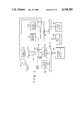
- FIG. 1 is a block diagram of one embodiment of the system of this invention.
- FIG. 2 is a graph of a typical image segment sequencing plan used to form a mosaic image.
- FIGS. 3A-3H are flow diagrams detailing the method of the invention.
- the concept of the invention herein described comprehends a computer-controlled, image processor system which automatically digitizes a sequence of magnified individual image segments from an object and composes the image segments into a single high-resolution wide-field-of-view mosaic image for recall and viewing on a CRT monitor. More specifically, the invention herein resides in a method for producing a high-resolution large-field-of-view electronic mosaic image of an object within an object plane by computer-controlled, multiple electronic image acquisition and assembly means, which method comprises in sequence:
- the invention also resides in a method of producing a graphical map from a stored wide-field-of-view high-resolution electronic image, the method comprising the steps:
- mapping marks under operator control from the fixed cursor position within the display window, said marks being stored in juxtaposition with the image, made visible on the display, and roamed in coincidence with the image portion visible in the display window such that accurate juxtaposition of the marks with the image is maintained;
- the operator first selects parameters which will govern acquisition of the mosaic image, including the x,y coordinates of, for example, the lower-left corner of the mosaic image, correspondingly, the x,y coordinates of the upper right corner of the image, and the objective magnification.
- the basic pixel size in x and y are then automatically computed, as well as the number of mosaic image pixels in x and y and the number of image segments in x and y.
- the computer-driven microscope stage is then automatically advanced to the coordinates corresponding to the lower left corner of the mosaic image.
- a video image of this field of view is then digitized, and a previously defined central portion (called a "vignette”) is transferred to contiguous addresses within a large image memory which correspond to the lower left region of the image.
- the stage is then advanced by a distance which exactly equals the spatial extent of one vignette image, and the process is repeated in a predetermined path in x and y until the entire mosaic image has been acquired.
- the operator is able to interactively manipulate the mosaic image in various ways, including zooming and roaming, much as he would do with the live image on the microscope by changing objectives and manipulating the stage.
- the invention permits viewing the high-resolution mosaic image on a standard-resolution monitor by means of pixel sampling. For example, a 4096 ⁇ 4096 pixel mosaic image can be displayed on a 512 ⁇ 512 pixel display monitor using a sampling ratio of 1:8. Thus, zoom up to a one-to-one sampling ratio is achieved without the loss in resolution that would accompany pixel replication methods.
- a benefit of the method is that of preserving the high-resolution image of a specimen obtained from high numerical aperture (N.A.) optics over the wide field of view image normally seen through low power, low N.A. objectives.
- Another benefit of using high N.A. objectives is their improved light collection efficiency.
- the invention minimizes the time that the specimen needs to be exposed to illumination. This combination is particularly applicable to those cases where the microscopic specimen is so light-sensitive that prolonged viewing of the live image through microscope occulars would have an adverse effect on the specimen, for example, in the case where rapidly-fading fluorescent tags are used.
- a further benefit results from the fact that because the mosaic image is displayed on a video monitor by pixel sampling, the contribution of the camera's point spread function to overall image blur is significantly reduced and the displayed image appears much more crisply resolved.
- FIG. 1 includes a microscope 10, typically a Nikon Fluophot, with an ultrawide Optiphot head 12 that is modified for mounting two standard format video cameras 14 and 16 with the oculars.
- Video camera 14 is a DAGE/MTI Model 68 silicon diode array vidicon
- video camera 16 is a DAGE/MTI Corporation Model 66 with a silicon intensified target (SIT) tube for low light level sensing.
- the outputs of cameras 14 and 16 are connected to the analog-to-digital (A/D) input terminals of image processor 18, typically an Imaging Technology, Inc.
- A/D analog-to-digital
- IP-512 system that includes three FB-512 boards, two AP-512 boards and an arithmetic logic unit (ALU) board, which communicates with the other components of the imaging system over the 22-bit Digital Equipment Co. (DEC) Q-bus 20.
- Image processor 18 functions to synchronize the input and output flow of digital image data, to digitize the analog camera output information, and to convert the processed digital data into analog form for viewing on display monitors 24 and 24A. Both displays are high-resolution color monitors (Mitsubishi Electronics of America, Inc. Model No. 3919).
- the microscope stage assembly 30 comprises a Nikon Diaphot stage on which are mounted two Burleigh Instruments Inc. IW-502 inchworm, x,y micropositioners and EN-372 optical encoders 34 and 36.
- Stage controller 38 comprises an Intel Corporation Model No. 8085 microprocessor for providing closed-loop control for both sets of positioners and encoders with I/O codes on an STD bus.
- the microprocessor is also programmed to communicate with a host computer system 40 over Q-bus 20.
- the inchworm micropositioners enable the operator to rapidly and smoothly move the stage across its full range of travel. Typical performance yields 1.0 micrometer absolute accuracy on 2 axes bidirectionally over a range of 50 mm on each axis.
- Both axes' positions are under simultaneous closed loop control, with position feedback derived from 1 micrometer linear optical encoders. Consequently, the stage can be moved and returned to its initial position with 1 micrometer accuracy and with no backlash.
- the communications interface with the host processor is able to support at least 150 coordinate pair updates per second.
- Computer system 40 comprises: a DEC LSI 11/23 computer which includes Q-bus 20; a 256 Kbyte main memory; a DLV-11J quad serial data interface; a Data Systems Design, Inc. Model No. DSD 880 30 Mbyte Winchester disk drive with a 1/2 Mbyte floppy disk; a Cipher Data Products Inc. M891, 9-track 3200 bpi cache streamer magnetic tape drive; a Microline hard copy printer manufactured by Okidata Corporation; a Hewlett Packard 7475A six pen plotter; and a DEC Model No. DRV 11 parallel interface to the stage controller 38.
- Communicating with computer 40 is a DEC Model No. VT100 Terminal 42.
- Image memory 50 and direct memory access (DMA) data-mover controller 52 are hardwired circuits that communicate directly with the I/O section of the host computer on Q-bus 20 to speed up the delivery of image size and stage position coordinate data, with the result that the display of the respective vignettes on the monitor 24 is rapidly achieved.
- DMA direct memory access
- the image memory 50 comprises a stack of four addressable memory boards, each with a 4 Mbyte (8 bits per byte) capacity, to provide storage for a 16 Mbyte, 4096 ⁇ 4096 pixel image with full eight bits/pixel resolution.
- Datamover controller 52 is a direct memory access (DMA) device capable of transferring data at high speed from a source address to a destination address on Q-bus 20. It is also responsible for selecting, as directed, an N ⁇ N pixel segment from image memory 50 for full display on the monitor 24.
- DMA direct memory access
- the operator places a specimen on the microscope stage assembly 30, selects a 1X objective lens, and selects either the normal 14 or low-light-level video camera 16. Live video from the camera is displayed on monitor 24, and the operator uses this low-magnification low-resolution live video image to focus and frame the desired section of the specimen.
- the stage is then fixed, the image on the monitor 24 is digitized, transferred to a static frame buffer, and displayed as a low-magnification static image on monitor 24A.
- the operator selects an objective lens with suitable resolution to acquire each image segment.
- the calibrated image pixel size DX and DY for this objective are obtained from a look-up table, and the maximum mosaic image size is computed and displayed as a rectangular mosaic image marker (MIM) that is drawn superimposed on the static low-magnification low-resolution image on monitor 24A.
- MIM rectangular mosaic image marker
- the operator manipulates, in this case, the lower-left and upper-right corners of the MIM independently to frame the area of interest.
- the stage coordinates of the lower left starting position are computed, as well as the number and positions of full and partial vignettes required to fill the MIM, as schematized in FIG. 2.
- the operator then may choose to eliminate partial vignettes at the right and top edges in order to significantly reduce the time required to capture the mosaic image.
- VT100 terminal 42 the operator activates the mosaic imaging sequence via the VT100 terminal 42.
- computer 40 advances the stage assembly 30 to a starting position and then steps it through a sequence of positions via stage controller 38.
- Each programmed position is precisely located in the center of its respective vignette.
- image processor 18 At each position, the acquired image segment from either video cameras 14 or 16 passes through image processor 18 to monitor 24, which the operator observes while critically focussing the stage.
- Image processor 18 then digitizes, frame-averages, and temporarily stores the 512 ⁇ 512 pixel video image for viewing on monitor 24A. A rectangular central portion of this video image, called a vignette, is transferred to image memory 50, as directed by the image DMA controller 52.
- the mosaic imaging sequence is complete when the assigned portion of the full 4096 ⁇ 4096 pixel image memory has been filled by the sequence of vignettes that have been acquired and stored in their respective image memory locations.
- FIG. 2 is a representation of a mosaic image which has been resolved in into an exemplary sequence of thirty-six image segments for digitization and storage in image memory 50. Note that the sequence depicted starts with the first image segment at the lower left corner of the mosaic and after following a serpentine path, ends in the upper left corner. This particular image segment sequence appears to be one of several efficient ways to proceed in that it minimizes stage motion.
- i, j column and row indexes are conventional right-hand coordinate system first quadrant descriptors and refer to a corresponding indexed image segment location in the mosaic.
- Fortran 77 syntax has been used to express the equations to facilitate their comprehension.
- FIGS. 3A through 3D detail the preliminary steps and FIGS. 3E through 3H describe the automatic sequencing steps of the method that can be implemented in the system of FIG. 1.
- Steps 111 and 112 of FIG. 3A initialize the system and specify mosaic and vignette dimensions (pixels) preparatory to capturing a mosaic image.
- Specification of vignette dimensions in Step 111 eliminates portions of the video camera raster that suffer from excessive geometrical distortion.
- Choice of the vignette dimensions in pixels dictates the dimensions in pixels of the image segments.
- Steps 113 through 118 allow the operator to capture a low-magnification low resolution image using a 1X objective, and to display the digitized image on monitor 24A. This static low-magnification image will be used to allow the operator to interactively specify the location and extent of the mosaic image.
- FIG. 3B shows steps 211 through 221 that enable the operator to: (1) select an appropriate microscope objective (step 212) and scale pixel size accordingly (step 213) using a look-up table set of values obtained by prior calibration; (2) compute the maximum size of the resulting mosaic image that can be stored in image memory (step 214) given the pixel NICOL, NIROW parameters (previous step 111) and the selected pixel size (step 213); (3) display the computed mosaic (x,y) limits with a mosaic image marker (MIM) on the low-magnification low-resolution static image (step 215); and (4) compute remainder pixels (NXPIX, NYPIX) (step 220) and establish the number of vignettes in x and y directions (NX, NY) needed to produce the complete mosaic (step 221).
- MIM mosaic image marker
- the mosaic image marker displays the boundary outlining the mosaic on the static low-magnification low-resolution image on monitor 24A and is positionable on the screen using keyboard commands from terminal 42.
- the operator designates the lower left (step 216) and upper right (step 217) limits of the mosaic for establishing values of the starting coordinates (IXBEG, IYBEG) and the coordinates of succeeding vignettes and for determining the total number of pixels in the x and y directions needed to cover the extent of the mosaic image (NICOL, NIROW).
- Entry points 211a, 215a and 217a of FIG. 3B are available to the operator to make changes to the objective lens selection, and to the starting and ending points on the mosaic, from choices detailed in FIG. 3D.
- the steps in the flow diagram of FIG. 3C are provided to enable the operator to make the decision whether the NXPIX and NYPIX remainder pixels need to be included in the mosaic. If these pixels are not needed (steps 312 through 315), vignette processing time is considerably shortened. For example, with reference to FIG. 2, should SNAP be elected (i.e., discard the remainder pixels) then the vignette sequence from the 36 possibles in this example would run 1, 2, 3, 4, 5, 8, 9, 10, 11, 12, 13, 14, 15, 16, 17, 20, 21, 22, 23, 24, 25, 26, 27, 28 and 29 (a savings of about 1/3 the processing time).
- Steps 316 through 321 the full sequence of 36 vignettes are recorded, with unfilled pixel bits appearing black in the digitized image displayed on monitor 24.
- Step 322 provides an opportunity for the operator to change the input parameters should he see that the display of the MIM (step 315) on monitor 24A does not cover the region required. Recall that the MIM characterizes the size of the mosaic image relative to the low-magnification low-resolution image of the specimen.
- FIG. 3E shows a set of steps, including the use of two subroutines, that provide for the sequential stepping of the microscope stage 30 on a serpentine path through the object plane of microscope 10 and digitizing for storage in image memory 50, a corresponding vignette at each step.
- next line is sequence from right to left with subroutine "GO -- LEFT" as soon as the (j) loop counter is incremented at the conclusion of digitizing the last vignette on the line.
- the process terminates.
- Steps 612 through 615 comprise a simple loop to acquire the horizontal sequence of vignettes.
- Step 612 tests for the final vignette on the row. If the current one is the final one, then steps 616 and 617 account for the possibility that the last vignette is a partial one.
- the GO -- LEFT sequence in FIG. 3G is similar, with the exception that the possible partial vignette is the first one encountered in this case, rather than the last.
- Step 811 uses the (i, j) indices passed from the calling routine to compute the stage coordinates for the current vignette, while step 812 drives the stage to the computed coordinates.
- Step 813 computes the corresponding image memory x and y addresses.
- Step 814 allows the operator to focus the live video image on viewing monitor 24.
- step 815 the image is digitized and in step 816 the vignette is transferred to the image memory with coordinates that were computed in step 813.
- the mosaic image may be recalled for viewing and manipulation using a variety of techniques, including roam and zoom, contrast enhancement, false coloring and spatial filtering, or even automatic feature detection and analysis.
- the large high-resolution mosaic image can be stored on disk, requiring a storage capacity of up to 16 Mbytes per image.
- An alternative for archival storage is a high performance 9-track tape drive system.
- mapping In addition to providing means for automatic digital analysis of wide-field high-resolution images, the present invention also comprehends manually driven scene analysis, herein referred to as mapping. This method relies on the ability of the system to electronically superimpose graphical marks over the electronically captured image.
- mapping marks may be continously generated from the cursor coordinates, analogous to ink flowing from a pen.
- the marks are displayed by replacing the image pixel value in image memory by a new value which is displayed as a high contrast color.
- Alternative means for storage of the marks is possible, for example, storage in the image memory bits unoccupied by image data or in a graphics overlay plane.
- the coordinates of the marks are also stored numerically as a vector list for further processing and analysis.
- mapping in the context of a high-resolution wide-field-of-view electronic mosaic image, it will also be appreciated that high-resolution wide-field images sensed and stored by any means whatsoever (for example, laser scanner, remote sensor, scanning electron microscope, or line scan camera) lend themselves to this method of electronic mapping.
- any means whatsoever for example, laser scanner, remote sensor, scanning electron microscope, or line scan camera
- the video camera Since electronic mosaic imaging requires that the edges of adjacent vignettes be precisely matched, the video camera must be one that produces a raster that is accurately aligned with the translation axes and generates a pixel size that is accurately known. A shading correction may be needed to eliminate the edge effects between adjacent image segments, particularly if quantitative photometric density measurements are to be made directly from the image.
- microscope embodiment described herein comprises a positionable stage with fixed microscope optics, it may be beneficial under some circumstances to fix the specimen stage and obtain vignette positioning by translating the microscope optics themselves. It will be understood that this method is within the spirit of the invention.
- the method described herein has already been found useful for imaging a field of fluorescently labeled cells in which the labeled cells could be accurately discerned only by using high-magnification, high N.A. objectives, while the object field of interest containing such cells extended over multiple, high-magnification microscope fields-of-view across the section.
Abstract
This invention relates to an imaging system with computer-controlled, multiple electronic image acquisition and assembly means for producing a graphical map from a stored wide-field-of-view high-resolution electronic image. The invention displays a contiguous small portion of the stored image within a display window and a cursor is superimposed on the image at a fixed position within the display window. The window can be roamed over the stored image for generating mapping marks from the fixed cursor and the mapping marks a stored in a separate memory.
Description
This is a division of application Ser. No. 725,636, filed Apr. 22, 1985, U.S. Pat. No. 4,673,988.
1. Field of the Invention
This invention relates to an imaging system with computer-controlled, multiple electronic image acquisition and assembly means for producing a high resolution, large-field electronic mosaic image from a series of smaller field image segments.
2. Background
In the field of microscopy, a microscopist must select an objective lens that affords sufficient spatial resolution and photometric sensitivity to analyze a specimen. Having selected an objective, in many cases, the resulting microscopic field of view covers only a small region of the specimen. Consequently, in order to examine the entire specimen, it is necessary to move the microscope stage in a plurality of steps. A single view of the entire specimen, however, is necessary both for contextual appreciation and for communicating the results of the analysis. The classical solution to this problem has been to prepare photomicrographs of the fields of view containing the specimen and to assemble a montage or mosaic of the photomicrographs to present a view of the whole specimen. This procedure suffers from several disadvantages: it is both tedious and time-consuming and results in a final product that is either too large or has insufficient magnification.
In current practice one often needs to acquire a video image of a microscopically-viewed specimen. Microscope video systems, by appropriate interfacing with computer-based hardware and software, permit the video image to be digitized and stored. Further operations, such as image processing and analysis, can then be performed on the digitized image. The present art, however, is unable to process more than a single digitized microscope field of view at a time, which creates difficulties in analysis and display of the complete specimen. In addition, in cases where the microscopic specimen is only briefly visible, as in the case where rapidly-fading fluorescent tags are used, rapid, multiple-field acquisition is a necessity. Solutions to these problems have not previously been available.
The present invention provides a means for the sequential capture and storage in a very large image memory of multiple digitized and frame-averaged small field image segments from adjacent fields of view. In addition, the invention provides means for matching the edges of the adjacent segments into a continuous field. Means are also provided for storage of the electronic mosaic image, and for real-time manipulation of the entire mosaic by the operator. The resulting composite digitized mosaic image simultaneously offers high resolution, high photometric sensitivity, and a wide field of view, while providing the advantages of electronic digital processing and analysis.
FIG. 1 is a block diagram of one embodiment of the system of this invention.
FIG. 2 is a graph of a typical image segment sequencing plan used to form a mosaic image.
FIGS. 3A-3H are flow diagrams detailing the method of the invention.
The concept of the invention herein described comprehends a computer-controlled, image processor system which automatically digitizes a sequence of magnified individual image segments from an object and composes the image segments into a single high-resolution wide-field-of-view mosaic image for recall and viewing on a CRT monitor. More specifically, the invention herein resides in a method for producing a high-resolution large-field-of-view electronic mosaic image of an object within an object plane by computer-controlled, multiple electronic image acquisition and assembly means, which method comprises in sequence:
(a) selecting a field of interest within the object plane;
(b) defining the pixel size in the object plane;
(c) computing the number of image pixels in the x and y directions required to cover the field of interest in the object plane;
(d) determining the number of pixels in the x and y directions of each image segment;
(e) computing image segment size in the object plane;
(f) determining the position of each image segment in the object plane and the sequence in which the image segments will be acquired;
(g) positioning the object with respect to an image sensor so that the initial image segment position in the sequence lies on the image sensor optical axis;
(h) digitizing the field of view of the image sensor;
(i) transferring the digitized field of view to a contiguous set of x,y locations in a mosaic image storage means corresponding to the image segment position in the object plane;
(j) positioning the object with respect to the image sensor so that the next image segment position in the sequence lies on the image sensor optical axis;
(k) digitizing the field of view of the image sensor;
(l) transferring the digitized field of view to a contiguous set of x,y locations in the mosaic image storage means corresponding to the image segment position in the object plane, said correspondence being chosen such that the boundaries of adjacent image segments in the mosaic image storage means are in substantial abutment and alignment;
(m) repeating steps (j), (k), and (l) until all image segments in the sequence have been digitized and stored in the mosaic image storage means; and
(n) recalling the mosaic image from the mosaic image storage means.
The invention also resides in a method of producing a graphical map from a stored wide-field-of-view high-resolution electronic image, the method comprising the steps:
(a) displaying a contiguous small portion of the stored wide-field-of-view high-resolution electronic image on a display monitor, said portion at any instant in time being within a display window as displayed on the display monitor;
(b) displaying an electronic visible cursor, superimposed on the displayed image, at a fixed location within the display window;
(c) roaming the display window within the stored wide-field-of-view high-resolution electronic image under operator control;
(d) generating mapping marks under operator control from the fixed cursor position within the display window, said marks being stored in juxtaposition with the image, made visible on the display, and roamed in coincidence with the image portion visible in the display window such that accurate juxtaposition of the marks with the image is maintained; and
(e) storing the x,y coordinates of the marks in a separate memory.
The operator first selects parameters which will govern acquisition of the mosaic image, including the x,y coordinates of, for example, the lower-left corner of the mosaic image, correspondingly, the x,y coordinates of the upper right corner of the image, and the objective magnification. The basic pixel size in x and y are then automatically computed, as well as the number of mosaic image pixels in x and y and the number of image segments in x and y. The computer-driven microscope stage is then automatically advanced to the coordinates corresponding to the lower left corner of the mosaic image. A video image of this field of view is then digitized, and a previously defined central portion (called a "vignette") is transferred to contiguous addresses within a large image memory which correspond to the lower left region of the image. The stage is then advanced by a distance which exactly equals the spatial extent of one vignette image, and the process is repeated in a predetermined path in x and y until the entire mosaic image has been acquired.
Once assembled, the operator is able to interactively manipulate the mosaic image in various ways, including zooming and roaming, much as he would do with the live image on the microscope by changing objectives and manipulating the stage. The invention permits viewing the high-resolution mosaic image on a standard-resolution monitor by means of pixel sampling. For example, a 4096×4096 pixel mosaic image can be displayed on a 512×512 pixel display monitor using a sampling ratio of 1:8. Thus, zoom up to a one-to-one sampling ratio is achieved without the loss in resolution that would accompany pixel replication methods.
A benefit of the method is that of preserving the high-resolution image of a specimen obtained from high numerical aperture (N.A.) optics over the wide field of view image normally seen through low power, low N.A. objectives. Another benefit of using high N.A. objectives is their improved light collection efficiency. Further, the invention minimizes the time that the specimen needs to be exposed to illumination. This combination is particularly applicable to those cases where the microscopic specimen is so light-sensitive that prolonged viewing of the live image through microscope occulars would have an adverse effect on the specimen, for example, in the case where rapidly-fading fluorescent tags are used. A further benefit results from the fact that because the mosaic image is displayed on a video monitor by pixel sampling, the contribution of the camera's point spread function to overall image blur is significantly reduced and the displayed image appears much more crisply resolved.
For purposes of illustration, the embodiment of FIG. 1 includes a microscope 10, typically a Nikon Fluophot, with an ultrawide Optiphot head 12 that is modified for mounting two standard format video cameras 14 and 16 with the oculars. Video camera 14 is a DAGE/MTI Model 68 silicon diode array vidicon, and video camera 16 is a DAGE/MTI Corporation Model 66 with a silicon intensified target (SIT) tube for low light level sensing. The outputs of cameras 14 and 16 are connected to the analog-to-digital (A/D) input terminals of image processor 18, typically an Imaging Technology, Inc. IP-512 system that includes three FB-512 boards, two AP-512 boards and an arithmetic logic unit (ALU) board, which communicates with the other components of the imaging system over the 22-bit Digital Equipment Co. (DEC) Q-bus 20. Image processor 18 functions to synchronize the input and output flow of digital image data, to digitize the analog camera output information, and to convert the processed digital data into analog form for viewing on display monitors 24 and 24A. Both displays are high-resolution color monitors (Mitsubishi Electronics of America, Inc. Model No. 3919).
The microscope stage assembly 30 comprises a Nikon Diaphot stage on which are mounted two Burleigh Instruments Inc. IW-502 inchworm, x,y micropositioners and EN-372 optical encoders 34 and 36. Stage controller 38 comprises an Intel Corporation Model No. 8085 microprocessor for providing closed-loop control for both sets of positioners and encoders with I/O codes on an STD bus. The microprocessor is also programmed to communicate with a host computer system 40 over Q-bus 20. The inchworm micropositioners enable the operator to rapidly and smoothly move the stage across its full range of travel. Typical performance yields 1.0 micrometer absolute accuracy on 2 axes bidirectionally over a range of 50 mm on each axis. Both axes' positions are under simultaneous closed loop control, with position feedback derived from 1 micrometer linear optical encoders. Consequently, the stage can be moved and returned to its initial position with 1 micrometer accuracy and with no backlash. The communications interface with the host processor is able to support at least 150 coordinate pair updates per second.
The image memory 50 comprises a stack of four addressable memory boards, each with a 4 Mbyte (8 bits per byte) capacity, to provide storage for a 16 Mbyte, 4096× 4096 pixel image with full eight bits/pixel resolution.
In the operation of the system, the operator places a specimen on the microscope stage assembly 30, selects a 1X objective lens, and selects either the normal 14 or low-light-level video camera 16. Live video from the camera is displayed on monitor 24, and the operator uses this low-magnification low-resolution live video image to focus and frame the desired section of the specimen. The stage is then fixed, the image on the monitor 24 is digitized, transferred to a static frame buffer, and displayed as a low-magnification static image on monitor 24A. The operator then selects an objective lens with suitable resolution to acquire each image segment. The calibrated image pixel size DX and DY for this objective are obtained from a look-up table, and the maximum mosaic image size is computed and displayed as a rectangular mosaic image marker (MIM) that is drawn superimposed on the static low-magnification low-resolution image on monitor 24A. The operator manipulates, in this case, the lower-left and upper-right corners of the MIM independently to frame the area of interest. Once the MIM is set, the stage coordinates of the lower left starting position are computed, as well as the number and positions of full and partial vignettes required to fill the MIM, as schematized in FIG. 2. At this point, the operator then may choose to eliminate partial vignettes at the right and top edges in order to significantly reduce the time required to capture the mosaic image.
Finally, the operator activates the mosaic imaging sequence via the VT100 terminal 42. Automatically, computer 40 advances the stage assembly 30 to a starting position and then steps it through a sequence of positions via stage controller 38. Each programmed position is precisely located in the center of its respective vignette. At each position, the acquired image segment from either video cameras 14 or 16 passes through image processor 18 to monitor 24, which the operator observes while critically focussing the stage. Image processor 18 then digitizes, frame-averages, and temporarily stores the 512×512 pixel video image for viewing on monitor 24A. A rectangular central portion of this video image, called a vignette, is transferred to image memory 50, as directed by the image DMA controller 52.
The mosaic imaging sequence is complete when the assigned portion of the full 4096×4096 pixel image memory has been filled by the sequence of vignettes that have been acquired and stored in their respective image memory locations.
To one skilled in the art, the following flow charts and description are sufficient to develop software needed to operate the microscope system disclosed herein.
FIG. 2 is a representation of a mosaic image which has been resolved in into an exemplary sequence of thirty-six image segments for digitization and storage in image memory 50. Note that the sequence depicted starts with the first image segment at the lower left corner of the mosaic and after following a serpentine path, ends in the upper left corner. This particular image segment sequence appears to be one of several efficient ways to proceed in that it minimizes stage motion.
In the definitions following, the i, j column and row indexes are conventional right-hand coordinate system first quadrant descriptors and refer to a corresponding indexed image segment location in the mosaic. Fortran 77 syntax has been used to express the equations to facilitate their comprehension.
__________________________________________________________________________
TABLE OF VARIABLE DEFINITIONS
__________________________________________________________________________
NVCOL, NVROW
            vignette format (pixels) - indicates the
            number of pixels comprising a vignette in
            the x, y directions respectively
            (e.g., 340 × 320)
NICOL, NIROW
            mosaic format (pixels) - indicates the
            number of pixels assigned to store the
            mosaic in image memory. Given in terms of
            numbers in the x, y directions,
            respectively. (e.g., 4096 × 4096)
DX, DY      pixel size (microns) - in x, y directions.
 DX * NVCOL  vignette size (microns) - in x, y
DY * NVROW  directions.
 DX * NICOL
            mosaic size (microns) - in x, y directions.
DY * NIROW
IXBEG, IYBEG
            mosaic starting location (microns) - the x,
            y coordinates of the lower left corner of
            the first vignette of the sequence to be
            digitized.
IXSTAGE (i) vignette location (microns) - the position
IYSTAGE (j) of the lower left corner of the (i, j)
            vignette in the stage coordinate system.
IXMEM (i)   vignette location (image memory coordinates)
IYMEM (j)
the storage location in memory of the
            lower left corner of the (i, j) vignette
            corresponding to values of IXSTAGE (i) and
            IYSTAGE (j) above.
NXPIX, NYPIX
            remainder pixels - the number of pixels in
            the x, y directions comprising the partial
            vignettes at both the upper- and right-hand
            edges of the mosaic. Specifically,
            NXPIX=ININT((FLOATI(NICOL)/FLOATI(NVCOL)-
            FLOATI(NICOL/NVCOL))*FLOATI(NVCOL))
            NYPIX=ININT((FLOATI(NIROW)/FLOATI(NVROW)-
            FLOATI(NIROW/NVROW))*FLOATI(NVROW))
NX, NY      total number of vignettes (complete or
            partial) to be recorded in the x and y
            directions, respectively. More
            specifically,
                   ((NICOL/NVCOL) + 1, NXPIX > 0
            NX =
                  NICOL/NVCOL, NXPIX = 0
                   (NIROW/NVROW) + 1, NYPIX > 0
            NY =
                  NIROW/NVROW, NYPIX = 0
__________________________________________________________________________
FIGS. 3A through 3D detail the preliminary steps and FIGS. 3E through 3H describe the automatic sequencing steps of the method that can be implemented in the system of FIG. 1.
FIG. 3B shows steps 211 through 221 that enable the operator to: (1) select an appropriate microscope objective (step 212) and scale pixel size accordingly (step 213) using a look-up table set of values obtained by prior calibration; (2) compute the maximum size of the resulting mosaic image that can be stored in image memory (step 214) given the pixel NICOL, NIROW parameters (previous step 111) and the selected pixel size (step 213); (3) display the computed mosaic (x,y) limits with a mosaic image marker (MIM) on the low-magnification low-resolution static image (step 215); and (4) compute remainder pixels (NXPIX, NYPIX) (step 220) and establish the number of vignettes in x and y directions (NX, NY) needed to produce the complete mosaic (step 221).
The mosaic image marker (MIM) displays the boundary outlining the mosaic on the static low-magnification low-resolution image on monitor 24A and is positionable on the screen using keyboard commands from terminal 42. By positioning the MIM, the operator designates the lower left (step 216) and upper right (step 217) limits of the mosaic for establishing values of the starting coordinates (IXBEG, IYBEG) and the coordinates of succeeding vignettes and for determining the total number of pixels in the x and y directions needed to cover the extent of the mosaic image (NICOL, NIROW).
The steps in the flow diagram of FIG. 3C are provided to enable the operator to make the decision whether the NXPIX and NYPIX remainder pixels need to be included in the mosaic. If these pixels are not needed (steps 312 through 315), vignette processing time is considerably shortened. For example, with reference to FIG. 2, should SNAP be elected (i.e., discard the remainder pixels) then the vignette sequence from the 36 possibles in this example would run 1, 2, 3, 4, 5, 8, 9, 10, 11, 12, 13, 14, 15, 16, 17, 20, 21, 22, 23, 24, 25, 26, 27, 28 and 29 (a savings of about 1/3 the processing time). On the other hand, should SNAP not be selected (steps 316 through 321), then the full sequence of 36 vignettes are recorded, with unfilled pixel bits appearing black in the digitized image displayed on monitor 24. Step 322 provides an opportunity for the operator to change the input parameters should he see that the display of the MIM (step 315) on monitor 24A does not cover the region required. Recall that the MIM characterizes the size of the mosaic image relative to the low-magnification low-resolution image of the specimen.
FIG. 3E shows a set of steps, including the use of two subroutines, that provide for the sequential stepping of the microscope stage 30 on a serpentine path through the object plane of microscope 10 and digitizing for storage in image memory 50, a corresponding vignette at each step. After j=1 initialization of a loop counter in step 512, step 515 tests to determine whether the vignette recording sequence moves from left to right with subroutine "GO-- RIGHT", step 517, or from right to left with subroutine "GO-- LEFT", step 516. Since j=1 is odd the former subroutine "GO-- RIGHT" is selected. Similarly, the next line is sequence from right to left with subroutine "GO-- LEFT" as soon as the (j) loop counter is incremented at the conclusion of digitizing the last vignette on the line. When the last row is encountered in step 518, the process terminates.
Subroutines GO-- RIGHT and GO-- LEFT are detailed in FIGS. 3F and 3G, respectively. In FIG. 3F, the vignette column counter is initialized in step 611. Steps 612 through 615 comprise a simple loop to acquire the horizontal sequence of vignettes. Step 612 tests for the final vignette on the row. If the current one is the final one, then steps 616 and 617 account for the possibility that the last vignette is a partial one. The GO-- LEFT sequence in FIG. 3G is similar, with the exception that the possible partial vignette is the first one encountered in this case, rather than the last.
Both directional sequences use subroutine GET-- DATA, FIG. 3H, to carry out stage motion, image digitization, and data transfer to image memory. Step 811 uses the (i, j) indices passed from the calling routine to compute the stage coordinates for the current vignette, while step 812 drives the stage to the computed coordinates. Step 813 computes the corresponding image memory x and y addresses. Step 814 allows the operator to focus the live video image on viewing monitor 24. In step 815 the image is digitized and in step 816 the vignette is transferred to the image memory with coordinates that were computed in step 813.
Once the mosaic image has been composed in image memory 50, it may be recalled for viewing and manipulation using a variety of techniques, including roam and zoom, contrast enhancement, false coloring and spatial filtering, or even automatic feature detection and analysis. The large high-resolution mosaic image can be stored on disk, requiring a storage capacity of up to 16 Mbytes per image. An alternative for archival storage is a high performance 9-track tape drive system.
In addition to providing means for automatic digital analysis of wide-field high-resolution images, the present invention also comprehends manually driven scene analysis, herein referred to as mapping. This method relies on the ability of the system to electronically superimpose graphical marks over the electronically captured image.
Note that if a given display pixel corresponds with exactly one stored mosaic image pixel, in general, a very small spatial extent of the mosaic image appears on the display monitor. This portion is referred to herein as the "display window"; as noted earlier, it is possible to roam the window throughout the stored mosaic image. The operator proceeds to create a map by "flying" the display window within the context of the mosaic image. Displayed on the monitor will be a fixed video cursor superimposed on the image, indicating the current addressed cartesian coordinates in the stored image. When the operator so indicates, mapping marks may be continously generated from the cursor coordinates, analogous to ink flowing from a pen. The marks are displayed by replacing the image pixel value in image memory by a new value which is displayed as a high contrast color. Alternative means for storage of the marks is possible, for example, storage in the image memory bits unoccupied by image data or in a graphics overlay plane. The coordinates of the marks are also stored numerically as a vector list for further processing and analysis. Optionally, it is possible for the operator to indicate discrete objects by discrete rather than continuous generation of mapping marks.
In addition to allowing mapping in the context of a high-resolution wide-field-of-view electronic mosaic image, it will also be appreciated that high-resolution wide-field images sensed and stored by any means whatsoever (for example, laser scanner, remote sensor, scanning electron microscope, or line scan camera) lend themselves to this method of electronic mapping.
There are two sources of geometrical distortion in an individual digitized image. They are distortion in the camera raster and in microscope optics. Each of them must be made small for accurate matching at the vignette boundaries. Solid state video cameras offer low geometrical distortion, although many other devices for image scanning can be readily applied, such as, e.g., line scan cameras, laser scanners, and flying spot scanners. Plan-apochromatic objectives appear to be adequate to minimize distortion. In cases where high photometric sensitivity is required, a high-sensitivity vidicon-based camera (such as a silicon intensified target (SIT) camera) is appropriate.
Since electronic mosaic imaging requires that the edges of adjacent vignettes be precisely matched, the video camera must be one that produces a raster that is accurately aligned with the translation axes and generates a pixel size that is accurately known. A shading correction may be needed to eliminate the edge effects between adjacent image segments, particularly if quantitative photometric density measurements are to be made directly from the image.
Although the microscope embodiment described herein comprises a positionable stage with fixed microscope optics, it may be beneficial under some circumstances to fix the specimen stage and obtain vignette positioning by translating the microscope optics themselves. It will be understood that this method is within the spirit of the invention.
Although the principle of this invention has been described in the context of a monochromatic optical microscopical imaging system, further applications of electronic mosaic imaging are envisioned, including other forms of microscopy, such as electron, X-ray, infrared, and acoustical imaging schemes, as well as assemblage from a non-microscopic two-dimensional image source such as, for example, a photographic image or series of images, thermographic images, or printed circuit boards.
The method described herein has already been found useful for imaging a field of fluorescently labeled cells in which the labeled cells could be accurately discerned only by using high-magnification, high N.A. objectives, while the object field of interest containing such cells extended over multiple, high-magnification microscope fields-of-view across the section.
Another example in which the technique has been found useful is the imaging of receptor autoradiographic material in which the radioactive label covers essentially the entire tissue section, yet the grains in the photographic emulsion forming the analytical signal can only be resolved at relatively high magnification. Accurate distinction between the autoradiographic analytical signal and light absorption in the underlying tissue section requires this level of magnification. Thus, accuracy in the quantitation of receptor autoradiograms is improved by the method of the present invention in comparison with methods relying on a single low-magnification field-of-view.
Claims (4)
1. Method of producing a graphical map from a stored wide-field-of-view high-resolution electronic image, the method comprising the steps:
(a) displaying a contiguous small portion of the stored wide-field-of-view high-resolution electronic image on a display monitor, said displayed image portion at any instant in time being within a display window as displayed on the display monitor;
(b) displaying an electronic visible cursor, superimposed on the displayed image portion, at a fixed position within the display window;
(c) roaming the display window within the stored wide-field-of-view high-resolution electronic image under operator control;
(d) generating mapping marks under operator control from the fixed cursor position within the display window, said mapping marks being stored in spatial relationship in juxtaposition with said stored image, made visible on said display monitor, and roamed in coincidence with the displayed image portion visible in the display window such that accurate juxtaposition of the marks with the image is maintained; and
(e) storing the x,y coordinates of the mapping marks in a separate memory.
2. The method of claim 1 wherein the wide-field-of-view high-resolution electronic image is acquired using non-mosaic imaging means.
3. The method of claim 1 wherein the mapping marks generated from the fixed cursor position within the display window are generated in a stream, the stream being switched on or off under operator control and being substantially continuous when switched on.
4. The method of claim 1 wherein the marks generated from the fixed cursor position within the display window are generated discretely, one or more at a time, under operator control.
Priority Applications (1)
| Application Number | Priority Date | Filing Date | Title |
|---|---|---|---|
| US06/879,443 US4760385A (en) | 1985-04-22 | 1986-06-27 | Electronic mosaic imaging process |
Applications Claiming Priority (2)
| Application Number | Priority Date | Filing Date | Title |
|---|---|---|---|
| US06/725,636 US4673988A (en) | 1985-04-22 | 1985-04-22 | Electronic mosaic imaging process |
| US06/879,443 US4760385A (en) | 1985-04-22 | 1986-06-27 | Electronic mosaic imaging process |
Related Parent Applications (1)
| Application Number | Title | Priority Date | Filing Date |
|---|---|---|---|
| US06/725,636 Division US4673988A (en) | 1985-04-22 | 1985-04-22 | Electronic mosaic imaging process |
Publications (1)
| Publication Number | Publication Date |
|---|---|
| US4760385A true US4760385A (en) | 1988-07-26 |
Family
ID=27111194
Family Applications (1)
| Application Number | Title | Priority Date | Filing Date |
|---|---|---|---|
| US06/879,443 Expired - Fee Related US4760385A (en) | 1985-04-22 | 1986-06-27 | Electronic mosaic imaging process |
Country Status (1)
| Country | Link |
|---|---|
| US (1) | US4760385A (en) |
Cited By (59)
| Publication number | Priority date | Publication date | Assignee | Title |
|---|---|---|---|---|
| WO1991005336A1 (en) * | 1989-09-29 | 1991-04-18 | The Regents Of The University Of California | Power-modulated laser devices |
| US5117112A (en) * | 1989-11-21 | 1992-05-26 | Jeol Ltd. | Method and apparatus for monitoring astigmatism and focus in electron microscope |
| US5260562A (en) * | 1989-09-29 | 1993-11-09 | Regents Of The University Of California | High-resolution light microscope using coherent light reflected from a target to modulate the power output from a laser |
| EP0533330B1 (en) * | 1991-09-17 | 1998-04-22 | Hitachi, Ltd. | A scanning microscope and a method of operating such a scanning microscope |
| US5859649A (en) * | 1995-05-15 | 1999-01-12 | Motorola, Inc. | Data processing system having display controller with bursting direct memory access |
| US6226392B1 (en) * | 1996-08-23 | 2001-05-01 | Bacus Research Laboratories, Inc. | Method and apparatus for acquiring and reconstructing magnified specimen images from a computer-controlled microscope |
| WO2001084209A2 (en) * | 2000-05-03 | 2001-11-08 | Dirk Soenksen | Fully automatic rapid microscope slide scanner |
| US20020051287A1 (en) * | 2000-07-25 | 2002-05-02 | Olympus Optical Co., Ltd. | Imaging apparatus for microscope |
| WO2002037159A2 (en) * | 2000-11-03 | 2002-05-10 | Arcturus Engineering, Inc. | Road map image for automated microdissection |
| US6404906B2 (en) | 1997-03-03 | 2002-06-11 | Bacus Research Laboratories,Inc. | Method and apparatus for acquiring and reconstructing magnified specimen images from a computer-controlled microscope |
| US20020097898A1 (en) * | 2001-01-16 | 2002-07-25 | Brown Carl S. | Coordinate calibration for scanning systems |
| EP1247246A1 (en) * | 1999-11-10 | 2002-10-09 | Lucid, Inc. | System for optically sectioning and mapping surgically excised tissue |
| US20030002746A1 (en) * | 2000-09-28 | 2003-01-02 | Yosuke Kusaka | Image creating device and image creating method |
| US20030039384A1 (en) * | 2000-12-19 | 2003-02-27 | Bacus Research Laboratories, Inc. | Method and apparatus for processing an image of a tissue sample microarray |
| US6633685B1 (en) * | 1998-08-05 | 2003-10-14 | Canon Kabushiki Kaisha | Method, apparatus, and storage media for image processing |
| US20040004614A1 (en) * | 2002-02-22 | 2004-01-08 | Bacus Laboratories, Inc. | Focusable virtual microscopy apparatus and method |
| US20040008894A1 (en) * | 1998-06-01 | 2004-01-15 | Zeineh Jack A. | Compression packaged image transmission for telemicroscopy |
| US6687419B1 (en) * | 1998-12-08 | 2004-02-03 | Synoptics Limited | Automatic image montage system |
| US20040027556A1 (en) * | 1997-02-07 | 2004-02-12 | Baer Thomas M. | Laser capture microdissection translation stage joystick |
| US20040113050A1 (en) * | 2002-12-17 | 2004-06-17 | Olszak Artur G. | Method and apparatus for limiting scanning imaging array data to characteristics of interest |
| US6775402B2 (en) | 1997-03-03 | 2004-08-10 | Bacus Laboratories, Inc. | Method and apparatus for creating a virtual microscope slide |
| US20040167806A1 (en) * | 2000-05-03 | 2004-08-26 | Aperio Technologies, Inc. | System and method for viewing virtual slides |
| US20040170325A1 (en) * | 2003-02-28 | 2004-09-02 | Aperio Technologies, Inc. | Systems and methods for image pattern recognition |
| US20040256538A1 (en) * | 2000-05-03 | 2004-12-23 | Allen Olson | Method and apparatus for pre-focus in a linear array based slide scanner |
| US6870625B1 (en) | 1999-11-04 | 2005-03-22 | Arcturus Bioscience, Inc. | Automated laser capture microdissection |
| US20060007345A1 (en) * | 2000-05-03 | 2006-01-12 | Allen Olson | System and method for assessing virtual slide image quality |
| US20060034543A1 (en) * | 2004-08-16 | 2006-02-16 | Bacus James V | Method and apparatus of mechanical stage positioning in virtual microscopy image capture |
| WO2006023675A2 (en) * | 2004-08-18 | 2006-03-02 | Tripath Imaging, Inc. | Microscopy system having automatic and interactive modes for forming a magnified mosaic image and associated method |
| US20060139621A1 (en) * | 2001-11-05 | 2006-06-29 | Baer Thomas M | Automated microdissection instrument |
| DE102005024063B3 (en) * | 2005-05-25 | 2006-07-06 | Soft Imaging System Gmbh | Method for optical scanning sample involves recording of individual image whereby in each case, it is evaluated by means of adaptive sensor unit with respect to contrast totally or partly |
| US20060171582A1 (en) * | 2005-01-27 | 2006-08-03 | Ole Eichhorn | Systems and methods for viewing three dimensional virtual slides |
| WO2006125466A1 (en) | 2005-05-25 | 2006-11-30 | Olympus Soft Imaging Solutions Gmbh | Method for optical scanning of a sample |
| US20060276974A1 (en) * | 2003-07-14 | 2006-12-07 | Trestle Acquisition Corp. | System for remote viewing and display of a slide |
| US7194118B1 (en) | 2000-11-10 | 2007-03-20 | Lucid, Inc. | System for optically sectioning and mapping surgically excised tissue |
| US20070147673A1 (en) * | 2005-07-01 | 2007-06-28 | Aperio Techologies, Inc. | System and Method for Single Optical Axis Multi-Detector Microscope Slide Scanner |
| US20070258114A1 (en) * | 2004-05-17 | 2007-11-08 | Jurgen Tumpner | Method and Device for Optically Scanning a Sample |
| US20080065645A1 (en) * | 2006-06-30 | 2008-03-13 | Aperio Technologies, Inc. | System and Method for Managing Images Over a Network |
| US20080124002A1 (en) * | 2006-06-30 | 2008-05-29 | Aperio Technologies, Inc. | Method for Storing and Retrieving Large Images Via DICOM |
| US7463761B2 (en) | 2004-05-27 | 2008-12-09 | Aperio Technologies, Inc. | Systems and methods for creating and viewing three dimensional virtual slides |
| US20090208134A1 (en) * | 2003-02-28 | 2009-08-20 | Aperio Technologies, Inc. | Image Processing and Analysis Framework |
| US20090244697A1 (en) * | 2005-08-26 | 2009-10-01 | Tuempner Juergen | Optical recording and/or reproduction unit |
| WO2010049651A1 (en) * | 2008-10-31 | 2010-05-06 | Novacyt | Procecure for preparing a processed virtual analysis image |
| US20100149364A1 (en) * | 2008-12-12 | 2010-06-17 | Keyence Corporation | Imaging Device |
| US20100149362A1 (en) * | 2008-12-12 | 2010-06-17 | Keyence Corporation | Imaging Device |
| WO2012024627A1 (en) * | 2010-08-20 | 2012-02-23 | Sakura Finetek U.S.A., Inc. | Digital microscope |
| CN102665031A (en) * | 2012-04-28 | 2012-09-12 | 华为技术有限公司 | Video signal processing method and photographic equipment |
| US20120314116A1 (en) * | 2006-11-20 | 2012-12-13 | Red.Com, Inc. | Focus assist system and method |
| US8571286B2 (en) | 2007-05-04 | 2013-10-29 | Leica Biosystems Imaging, Inc. | System and method for quality assurance in pathology |
| US8705825B2 (en) | 2009-12-11 | 2014-04-22 | Leica Biosystems Imaging, Inc. | Signal to noise ratio in digital pathology image analysis |
| US8715955B2 (en) | 2004-09-09 | 2014-05-06 | Life Technologies Corporation | Laser microdissection apparatus and method |
| US8743195B2 (en) | 2008-10-24 | 2014-06-03 | Leica Biosystems Imaging, Inc. | Whole slide fluorescence scanner |
| US20140160264A1 (en) * | 2012-12-10 | 2014-06-12 | The Johns Hopkins University | Augmented field of view imaging system |
| US9310598B2 (en) | 2009-03-11 | 2016-04-12 | Sakura Finetek U.S.A., Inc. | Autofocus method and autofocus device |
| US9692958B2 (en) | 2006-11-20 | 2017-06-27 | Red.Com, Inc. | Focus assist system and method |
| US20170242235A1 (en) * | 2014-08-18 | 2017-08-24 | Viewsiq Inc. | System and method for embedded images in large field-of-view microscopic scans |
| US10007102B2 (en) | 2013-12-23 | 2018-06-26 | Sakura Finetek U.S.A., Inc. | Microscope with slide clamping assembly |
| US10156501B2 (en) | 2001-11-05 | 2018-12-18 | Life Technologies Corporation | Automated microdissection instrument for determining a location of a laser beam projection on a worksurface area |
| US10269094B2 (en) | 2013-04-19 | 2019-04-23 | Sakura Finetek U.S.A., Inc. | Method for generating a composite image of an object composed of multiple sub-images |
| US11280803B2 (en) | 2016-11-22 | 2022-03-22 | Sakura Finetek U.S.A., Inc. | Slide management system |
Citations (3)
| Publication number | Priority date | Publication date | Assignee | Title |
|---|---|---|---|---|
| US4355805A (en) * | 1977-09-30 | 1982-10-26 | Sanders Associates, Inc. | Manually programmable video gaming system |
| USRE31200E (en) * | 1976-01-19 | 1983-04-05 | Xtrak Corporation | Raster scan display apparatus for dynamically viewing image elements stored in a random access memory array |
| US4517658A (en) * | 1979-11-06 | 1985-05-14 | Tokyo Shibaura Denki Kabushiki Kaisha | Picture information filing system for permanently storing portions of previously permanently stored data logically combining the portions |
-
1986
- 1986-06-27 US US06/879,443 patent/US4760385A/en not_active Expired - Fee Related
Patent Citations (4)
| Publication number | Priority date | Publication date | Assignee | Title |
|---|---|---|---|---|
| USRE31200E (en) * | 1976-01-19 | 1983-04-05 | Xtrak Corporation | Raster scan display apparatus for dynamically viewing image elements stored in a random access memory array |
| USRE31200F1 (en) * | 1976-01-19 | 1990-05-29 | Raster scan display apparatus for dynamically viewing image elements stored in a random access memory array | |
| US4355805A (en) * | 1977-09-30 | 1982-10-26 | Sanders Associates, Inc. | Manually programmable video gaming system |
| US4517658A (en) * | 1979-11-06 | 1985-05-14 | Tokyo Shibaura Denki Kabushiki Kaisha | Picture information filing system for permanently storing portions of previously permanently stored data logically combining the portions |
Non-Patent Citations (2)
| Title |
|---|
| Kaehler, Carol et al. "McParnt", Apple Computer, Inc. 1983, pp. 1-17. |
| Kaehler, Carol et al. McParnt , Apple Computer, Inc. 1983, pp. 1 17. * |
Cited By (210)
| Publication number | Priority date | Publication date | Assignee | Title |
|---|---|---|---|---|
| WO1991005336A1 (en) * | 1989-09-29 | 1991-04-18 | The Regents Of The University Of California | Power-modulated laser devices |
| AU639496B2 (en) * | 1989-09-29 | 1993-07-29 | Regents Of The University Of California, The | Power-modulated laser devices |
| US5260562A (en) * | 1989-09-29 | 1993-11-09 | Regents Of The University Of California | High-resolution light microscope using coherent light reflected from a target to modulate the power output from a laser |
| US5029023A (en) * | 1989-09-29 | 1991-07-02 | Regents Of The University Of California | Laser-amplified motion detector and method |
| US5117112A (en) * | 1989-11-21 | 1992-05-26 | Jeol Ltd. | Method and apparatus for monitoring astigmatism and focus in electron microscope |
| EP0533330B1 (en) * | 1991-09-17 | 1998-04-22 | Hitachi, Ltd. | A scanning microscope and a method of operating such a scanning microscope |
| US5859649A (en) * | 1995-05-15 | 1999-01-12 | Motorola, Inc. | Data processing system having display controller with bursting direct memory access |
| US7110586B2 (en) | 1996-08-23 | 2006-09-19 | Bacus Laboratories, Inc. | Apparatus for remote control of a microscope |
| US6674884B2 (en) | 1996-08-23 | 2004-01-06 | Bacus Laboratories, Inc. | Apparatus for remote control of a microscope |
| US6226392B1 (en) * | 1996-08-23 | 2001-05-01 | Bacus Research Laboratories, Inc. | Method and apparatus for acquiring and reconstructing magnified specimen images from a computer-controlled microscope |
| US20040136582A1 (en) * | 1996-08-23 | 2004-07-15 | Bacus Laboratories, Inc. | Apparatus for remote control of a microscope |
| US6924889B2 (en) | 1997-02-07 | 2005-08-02 | Arcturus Bioscience, Inc. | Laser capture microdissection vacuum hold-down |
| US7012676B2 (en) | 1997-02-07 | 2006-03-14 | Arcturus Bioscience, Inc. | Laser capture microdissection translation stage joystick |
| US20040106206A1 (en) * | 1997-02-07 | 2004-06-03 | Baer Thomas M. | Laser capture microdissection vacuum hold-down |
| US20040027556A1 (en) * | 1997-02-07 | 2004-02-12 | Baer Thomas M. | Laser capture microdissection translation stage joystick |
| US6775402B2 (en) | 1997-03-03 | 2004-08-10 | Bacus Laboratories, Inc. | Method and apparatus for creating a virtual microscope slide |
| US7146372B2 (en) | 1997-03-03 | 2006-12-05 | Olympus America Inc. | Method and apparatus for creating a virtual microscope slide |
| US20050254696A1 (en) * | 1997-03-03 | 2005-11-17 | Bacus Laboratories, Inc. | Method and apparatus for creating a virtual microscope slide |
| US8625920B2 (en) | 1997-03-03 | 2014-01-07 | Olympus America Inc. | Method and apparatus for creating a virtual microscope slide |
| US20040236773A1 (en) * | 1997-03-03 | 2004-11-25 | Bacus Laboratories, Inc. | Method and apparatus for creating a virtual microscope slide |
| US6404906B2 (en) | 1997-03-03 | 2002-06-11 | Bacus Research Laboratories,Inc. | Method and apparatus for acquiring and reconstructing magnified specimen images from a computer-controlled microscope |
| US8036868B2 (en) | 1998-06-01 | 2011-10-11 | Carl Zeiss Microimaging Gmbh | Intergrated systems and methods of virtual or live microscope slide presentation |
| US7505616B2 (en) | 1998-06-01 | 2009-03-17 | Carl Zeiss Microimaging Ais, Inc. | System and method for reconstructing a diagnostic trajectory |
| US20100073472A1 (en) * | 1998-06-01 | 2010-03-25 | Carl Zeiss Microlmaging Ais, Inc. | Intergrated virtual slide and live microscope system |
| US7916913B2 (en) | 1998-06-01 | 2011-03-29 | Carl Zeiss Microimaging Gmbh | System and method for reconstructing a diagnostic trajectory |
| US7224839B2 (en) | 1998-06-01 | 2007-05-29 | Clarient, Inc. | Compression packaged image transmission for telemicroscopy |
| US20060251331A1 (en) * | 1998-06-01 | 2006-11-09 | Trestle Acquisition Corp. | System and method for reconstructing a diagnostic trajectory |
| US7391894B2 (en) | 1998-06-01 | 2008-06-24 | Carl Zeiss Microimaging Ais, Inc. | System and method for remote navigation of a specimen |
| US20100067759A1 (en) * | 1998-06-01 | 2010-03-18 | Zeineh Jack A | System and Method for Remote Navigation of a Specimen |
| US7916916B2 (en) | 1998-06-01 | 2011-03-29 | Carl Zeiss Microimaging Gmbh | System and method for remote navigation of a specimen |
| US20040008894A1 (en) * | 1998-06-01 | 2004-01-15 | Zeineh Jack A. | Compression packaged image transmission for telemicroscopy |
| US20060251309A1 (en) * | 1998-06-01 | 2006-11-09 | Trestle Acquisition Corp. | System and method for remote navigation of a specimen |
| US6633685B1 (en) * | 1998-08-05 | 2003-10-14 | Canon Kabushiki Kaisha | Method, apparatus, and storage media for image processing |
| US7809732B2 (en) * | 1998-08-05 | 2010-10-05 | Canon Kabushiki Kaisha | Method, apparatus, and storage media for image processing |
| US20040022453A1 (en) * | 1998-08-05 | 2004-02-05 | Canon Kabukshiki Kaisha | Method, apparatus, and storage media for image processing |
| US6687419B1 (en) * | 1998-12-08 | 2004-02-03 | Synoptics Limited | Automatic image montage system |
| US6870625B1 (en) | 1999-11-04 | 2005-03-22 | Arcturus Bioscience, Inc. | Automated laser capture microdissection |
| US20050089949A1 (en) * | 1999-11-04 | 2005-04-28 | Baer Thomas M. | Automated laser capture microdissection |
| US7148966B2 (en) | 1999-11-04 | 2006-12-12 | Arcturus Bioscience, Inc. | Automated laser capture microdissection |
| US20060114456A1 (en) * | 1999-11-04 | 2006-06-01 | Baer Thomas M | Automated laser capture microdissection |
| US7027133B2 (en) | 1999-11-04 | 2006-04-11 | Arcturus Bioscience, Inc. | Automated laser capture microdissection |
| EP1247246A1 (en) * | 1999-11-10 | 2002-10-09 | Lucid, Inc. | System for optically sectioning and mapping surgically excised tissue |
| EP1247246A4 (en) * | 1999-11-10 | 2006-06-07 | Lucid Inc | System for optically sectioning and mapping surgically excised tissue |
| US8731260B2 (en) | 2000-05-03 | 2014-05-20 | Leica Biosystems Imaging, Inc. | Data management in a linear-array-based microscope slide scanner |
| EP2282230A2 (en) | 2000-05-03 | 2011-02-09 | Aperio Technologies, Inc. | Fully automatic rapid microscope slide scanner |
| JP2019056917A (en) * | 2000-05-03 | 2019-04-11 | ライカ バイオシステムズ イメージング インコーポレイテッドLeica Biosystems Imaging, Inc. | Fully automatic rapid microscope slide scanner |
| US20060007345A1 (en) * | 2000-05-03 | 2006-01-12 | Allen Olson | System and method for assessing virtual slide image quality |
| US7978894B2 (en) | 2000-05-03 | 2011-07-12 | Aperio Technologies, Inc. | Fully automatic rapid microscope slide scanner |
| US7035478B2 (en) | 2000-05-03 | 2006-04-25 | Aperio Technologies, Inc. | System and method for data management in a linear-array-based microscope slide scanner |
| US20110141263A1 (en) * | 2000-05-03 | 2011-06-16 | Aperio Technologies, Inc. | Achieving Focus in a Digital Pathology System |
| US20050270638A1 (en) * | 2000-05-03 | 2005-12-08 | Soenksen Dirk G | Fully automatic rapid microscope slide scanner |
| US20040256538A1 (en) * | 2000-05-03 | 2004-12-23 | Allen Olson | Method and apparatus for pre-focus in a linear array based slide scanner |
| EP2282230A3 (en) * | 2000-05-03 | 2011-05-25 | Aperio Technologies, Inc. | Fully automatic rapid microscope slide scanner |
| US7949168B2 (en) | 2000-05-03 | 2011-05-24 | Aperio Technologies, Inc. | Data management in a linear-array-based microscope slide scanner |
| US20040252875A1 (en) * | 2000-05-03 | 2004-12-16 | Aperio Technologies, Inc. | System and method for data management in a linear-array-based microscope slide scanner |
| US9851550B2 (en) | 2000-05-03 | 2017-12-26 | Leica Biosystems Imaging, Inc. | Fully automatic rapid microscope slide scanner |
| JP2017194700A (en) * | 2000-05-03 | 2017-10-26 | ライカ バイオシステムズ イメージング インコーポレイテッド | Fully automatic rapid microscope slide scanner |
| US20110221882A1 (en) * | 2000-05-03 | 2011-09-15 | Aperio Technologies, Inc. | Data Management in a Linear-Array-Based Microscope Slide Scanner |
| US20040167806A1 (en) * | 2000-05-03 | 2004-08-26 | Aperio Technologies, Inc. | System and method for viewing virtual slides |
| US6711283B1 (en) | 2000-05-03 | 2004-03-23 | Aperio Technologies, Inc. | Fully automatic rapid microscope slide scanner |
| JP2017194699A (en) * | 2000-05-03 | 2017-10-26 | ライカ バイオシステムズ イメージング インコーポレイテッド | Fully automatic rapid microscope slide scanner |
| US8055042B2 (en) | 2000-05-03 | 2011-11-08 | Aperio Technologies, Inc. | Fully automatic rapid microscope slide scanner |
| US8094902B2 (en) | 2000-05-03 | 2012-01-10 | Aperio Technologies, Inc. | Data management in a linear-array-based microscope slide scanner |
| WO2001084209A3 (en) * | 2000-05-03 | 2002-12-19 | Dirk Soenksen | Fully automatic rapid microscope slide scanner |
| US20070036462A1 (en) * | 2000-05-03 | 2007-02-15 | Crandall Greg J | System and Method for Data Management in a Linear-Array-Based Microscope Slide Scanner |
| US7893988B2 (en) | 2000-05-03 | 2011-02-22 | Aperio Technologies, Inc. | Method for pre-focus of digital slides |
| US8103082B2 (en) | 2000-05-03 | 2012-01-24 | Aperio Technologies, Inc. | Optimizing virtual slide image quality |
| US9729749B2 (en) | 2000-05-03 | 2017-08-08 | Leica Biosystems Imaging, Inc. | Data management in a linear-array-based microscope slide scanner |
| JP2019049751A (en) * | 2000-05-03 | 2019-03-28 | ライカ バイオシステムズ イメージング インコーポレイテッドLeica Biosystems Imaging, Inc. | Fully automatic rapid microscope slide scanner |
| US8755579B2 (en) | 2000-05-03 | 2014-06-17 | Leica Biosystems Imaging, Inc. | Fully automatic rapid microscope slide scanner |
| US7826649B2 (en) | 2000-05-03 | 2010-11-02 | Aperio Technologies, Inc. | Data management in a linear-array-based microscope slide scanner |
| US9723036B2 (en) | 2000-05-03 | 2017-08-01 | Leica Biosystems Imaging, Inc. | Viewing digital slides |
| US9535243B2 (en) | 2000-05-03 | 2017-01-03 | Leica Biosystems Imaging, Inc. | Optimizing virtual slide image quality |
| US8582849B2 (en) | 2000-05-03 | 2013-11-12 | Leica Biosystems Imaging, Inc. | Viewing digital slides |
| US7428324B2 (en) | 2000-05-03 | 2008-09-23 | Aperio Technologies, Inc. | System and method for data management in a linear-array-based microscope slide scanner |
| US9521309B2 (en) | 2000-05-03 | 2016-12-13 | Leica Biosystems Imaging, Inc. | Data management in a linear-array-based microscope slide scanner |
| EP1990667A1 (en) | 2000-05-03 | 2008-11-12 | Dirk Soenksen | Fully automatic rapid microscope slide scanner |
| US7457446B2 (en) | 2000-05-03 | 2008-11-25 | Aperio Technologies, Inc. | Fully automatic rapid microscope slide scanner |
| US8456522B2 (en) | 2000-05-03 | 2013-06-04 | Aperio Technologies, Inc. | Achieving focus in a digital pathology system |
| US20090028414A1 (en) * | 2000-05-03 | 2009-01-29 | Aperio Technologies, Inc. | Data Management in a Linear-Array-Based Microscope Slide Scanner |
| US8385619B2 (en) | 2000-05-03 | 2013-02-26 | Aperio Technologies, Inc. | Fully automatic rapid microscope slide scanner |
| US7518652B2 (en) | 2000-05-03 | 2009-04-14 | Aperio Technologies, Inc. | Method and apparatus for pre-focus in a linear array based slide scanner |
| WO2001084209A2 (en) * | 2000-05-03 | 2001-11-08 | Dirk Soenksen | Fully automatic rapid microscope slide scanner |
| US20090141126A1 (en) * | 2000-05-03 | 2009-06-04 | Aperio Technologies, Inc. | Fully Automatic Rapid Microscope Slide Scanner |
| JP2016167080A (en) * | 2000-05-03 | 2016-09-15 | ライカ バイオシステムズ イメージング インコーポレイテッドAperio Technologies, Inc. | Fully automatic rapid microscope slide scanner |
| US8805050B2 (en) | 2000-05-03 | 2014-08-12 | Leica Biosystems Imaging, Inc. | Optimizing virtual slide image quality |
| US7738688B2 (en) | 2000-05-03 | 2010-06-15 | Aperio Technologies, Inc. | System and method for viewing virtual slides |
| US9386211B2 (en) | 2000-05-03 | 2016-07-05 | Leica Biosystems Imaging, Inc. | Fully automatic rapid microscope slide scanner |
| US9213177B2 (en) | 2000-05-03 | 2015-12-15 | Leica Biosystems Imaging, Inc. | Achieving focus in a digital pathology system |
| US7646495B2 (en) | 2000-05-03 | 2010-01-12 | Aperio Technologies, Inc. | System and computer readable medium for pre-focus of digital slides |
| US20100027856A1 (en) * | 2000-05-03 | 2010-02-04 | Aperio Technologies, Inc. | Method for Pre-focus of Digital Slides |
| US7668362B2 (en) | 2000-05-03 | 2010-02-23 | Aperio Technologies, Inc. | System and method for assessing virtual slide image quality |
| US20020051287A1 (en) * | 2000-07-25 | 2002-05-02 | Olympus Optical Co., Ltd. | Imaging apparatus for microscope |
| US7260270B2 (en) * | 2000-09-28 | 2007-08-21 | Nikon Corporation | Image creating device and image creating method |
| US20030002746A1 (en) * | 2000-09-28 | 2003-01-02 | Yosuke Kusaka | Image creating device and image creating method |
| WO2002037159A2 (en) * | 2000-11-03 | 2002-05-10 | Arcturus Engineering, Inc. | Road map image for automated microdissection |
| US20020090122A1 (en) * | 2000-11-03 | 2002-07-11 | Baer Thomas M. | Road map image guide for automated microdissection |
| WO2002037159A3 (en) * | 2000-11-03 | 2002-08-29 | Arcturus Eng Inc | Road map image for automated microdissection |
| US7194118B1 (en) | 2000-11-10 | 2007-03-20 | Lucid, Inc. | System for optically sectioning and mapping surgically excised tissue |
| US7031507B2 (en) | 2000-12-19 | 2006-04-18 | Bacus Laboratories, Inc. | Method and apparatus for processing an image of a tissue sample microarray |
| US20030039384A1 (en) * | 2000-12-19 | 2003-02-27 | Bacus Research Laboratories, Inc. | Method and apparatus for processing an image of a tissue sample microarray |
| US20020097898A1 (en) * | 2001-01-16 | 2002-07-25 | Brown Carl S. | Coordinate calibration for scanning systems |
| US7062091B2 (en) * | 2001-01-16 | 2006-06-13 | Applied Precision, Llc | Coordinate calibration for scanning systems |
| US10156501B2 (en) | 2001-11-05 | 2018-12-18 | Life Technologies Corporation | Automated microdissection instrument for determining a location of a laser beam projection on a worksurface area |
| US8722357B2 (en) | 2001-11-05 | 2014-05-13 | Life Technologies Corporation | Automated microdissection instrument |
| US20060139621A1 (en) * | 2001-11-05 | 2006-06-29 | Baer Thomas M | Automated microdissection instrument |
| US20100074489A1 (en) * | 2002-02-22 | 2010-03-25 | Olympus America Inc. | Focusable virtual microscopy apparatus and method |
| US20110181622A1 (en) * | 2002-02-22 | 2011-07-28 | Olympus America Inc. | Focusable virtual microscopy apparatus and method |
| US8306300B2 (en) | 2002-02-22 | 2012-11-06 | Olympus America Inc. | Focusable virtual microscopy apparatus and method |
| US7925067B2 (en) | 2002-02-22 | 2011-04-12 | Olympus America Inc. | Focusable virtual microscopy apparatus and method |
| US20040004614A1 (en) * | 2002-02-22 | 2004-01-08 | Bacus Laboratories, Inc. | Focusable virtual microscopy apparatus and method |
| US7596249B2 (en) | 2002-02-22 | 2009-09-29 | Olympus America Inc. | Focusable virtual microscopy apparatus and method |
| US20040113050A1 (en) * | 2002-12-17 | 2004-06-17 | Olszak Artur G. | Method and apparatus for limiting scanning imaging array data to characteristics of interest |
| US7034317B2 (en) * | 2002-12-17 | 2006-04-25 | Dmetrix, Inc. | Method and apparatus for limiting scanning imaging array data to characteristics of interest |
| US20040170325A1 (en) * | 2003-02-28 | 2004-09-02 | Aperio Technologies, Inc. | Systems and methods for image pattern recognition |
| US8780401B2 (en) | 2003-02-28 | 2014-07-15 | Leica Biosystems Imaging, Inc. | Systems and methods for analyzing digital slide images using algorithms constrained by parameter data |
| US8199358B2 (en) | 2003-02-28 | 2012-06-12 | Aperio Technologies, Inc. | Digital slide image analysis |
| US7602524B2 (en) | 2003-02-28 | 2009-10-13 | Aperio Technologies, Inc. | Image processing and analysis framework |
| US7257268B2 (en) | 2003-02-28 | 2007-08-14 | Aperio Technologies, Inc. | Systems and methods for image pattern recognition |
| US8467083B2 (en) | 2003-02-28 | 2013-06-18 | Aperio Technologies, Inc. | Framework for processing the content of a digital image of a microscope sample |
| US7844125B2 (en) | 2003-02-28 | 2010-11-30 | Aperio Technologies, Inc. | Systems and methods for image pattern recognition |
| US9019546B2 (en) | 2003-02-28 | 2015-04-28 | Leica Biosystems Imaging, Inc. | Image processing of digital slide images based on a macro |
| US20090208134A1 (en) * | 2003-02-28 | 2009-08-20 | Aperio Technologies, Inc. | Image Processing and Analysis Framework |
| US20110187846A1 (en) * | 2003-07-14 | 2011-08-04 | Carl Zeiss Microimaging Gmbh | System for remote viewing and display of a slide |
| US20060276974A1 (en) * | 2003-07-14 | 2006-12-07 | Trestle Acquisition Corp. | System for remote viewing and display of a slide |
| US8139105B2 (en) | 2004-05-17 | 2012-03-20 | Olympus Soft Imaging Solutions Gmbh | Method and device for optically scanning a sample |
| US20070258114A1 (en) * | 2004-05-17 | 2007-11-08 | Jurgen Tumpner | Method and Device for Optically Scanning a Sample |
| EP1747421B1 (en) * | 2004-05-17 | 2018-10-10 | Olympus Soft Imaging Solutions GmbH | Method and device for optically scanning a sample |
| US20100177166A1 (en) * | 2004-05-27 | 2010-07-15 | Aperio Technologies, Inc. | Creating and Viewing Three Dimensional Virtual Slides |
| US20110090223A1 (en) * | 2004-05-27 | 2011-04-21 | Aperio Technologies, Inc. | Creating and viewing three dimensional virtual slides |
| US8923597B2 (en) | 2004-05-27 | 2014-12-30 | Leica Biosystems Imaging, Inc. | Creating and viewing three dimensional virtual slides |
| US9069179B2 (en) | 2004-05-27 | 2015-06-30 | Leica Biosystems Imaging, Inc. | Creating and viewing three dimensional virtual slides |
| US8565480B2 (en) | 2004-05-27 | 2013-10-22 | Leica Biosystems Imaging, Inc. | Creating and viewing three dimensional virtual slides |
| US7463761B2 (en) | 2004-05-27 | 2008-12-09 | Aperio Technologies, Inc. | Systems and methods for creating and viewing three dimensional virtual slides |
| US7860292B2 (en) | 2004-05-27 | 2010-12-28 | Aperio Technologies, Inc. | Creating and viewing three dimensional virtual slides |
| US20090116733A1 (en) * | 2004-05-27 | 2009-05-07 | Aperio Technologies, Inc. | Systems and Methods for Creating and Viewing Three Dimensional Virtual Slides |
| US7689024B2 (en) | 2004-05-27 | 2010-03-30 | Aperio Technologies, Inc. | Systems and methods for creating and viewing three dimensional virtual slides |
| US7792338B2 (en) | 2004-08-16 | 2010-09-07 | Olympus America Inc. | Method and apparatus of mechanical stage positioning in virtual microscopy image capture |
| US20060034543A1 (en) * | 2004-08-16 | 2006-02-16 | Bacus James V | Method and apparatus of mechanical stage positioning in virtual microscopy image capture |
| WO2006023675A3 (en) * | 2004-08-18 | 2006-04-20 | Tripath Imaging Inc | Microscopy system having automatic and interactive modes for forming a magnified mosaic image and associated method |
| US20090196526A1 (en) * | 2004-08-18 | 2009-08-06 | Tripath Imaging, Inc. | Microscopy system having automatic and interactive modes for forming a magnified mosaic image and associated method |
| WO2006023675A2 (en) * | 2004-08-18 | 2006-03-02 | Tripath Imaging, Inc. | Microscopy system having automatic and interactive modes for forming a magnified mosaic image and associated method |
| US20060133657A1 (en) * | 2004-08-18 | 2006-06-22 | Tripath Imaging, Inc. | Microscopy system having automatic and interactive modes for forming a magnified mosaic image and associated method |
| US8715955B2 (en) | 2004-09-09 | 2014-05-06 | Life Technologies Corporation | Laser microdissection apparatus and method |
| US11703428B2 (en) | 2004-09-25 | 2023-07-18 | Life Technologies Corporation | Automated microdissection instrument and method for processing a biological sample |
| US11175203B2 (en) | 2004-09-25 | 2021-11-16 | Life Technologies Corporation | Automated microdissection instrument using tracking information |
| US10605706B2 (en) | 2004-09-25 | 2020-03-31 | Life Technologies Corporation | Automated microdissection instrument with controlled focusing during movement of a laser beam across a tissue sample |
| US20100321387A1 (en) * | 2005-01-27 | 2010-12-23 | Aperio Technologies, Inc. | Viewing Three Dimensional Digital Slides |
| US20060171582A1 (en) * | 2005-01-27 | 2006-08-03 | Ole Eichhorn | Systems and methods for viewing three dimensional virtual slides |
| US9349208B2 (en) | 2005-01-27 | 2016-05-24 | Leica Biosystems Imaging, Inc. | Viewing three dimensional digital slides |
| US8620047B2 (en) | 2005-01-27 | 2013-12-31 | Leica Biosystems Imaging, Inc. | Viewing three dimensional digital slides |
| US8189891B2 (en) | 2005-01-27 | 2012-05-29 | Aperio Technologies, Inc. | Viewing three dimensional digital slides |
| US8953859B2 (en) | 2005-01-27 | 2015-02-10 | Leica Biosystems Imaging, Inc. | Viewing three dimensional digital slides |
| US7787674B2 (en) | 2005-01-27 | 2010-08-31 | Aperio Technologies, Incorporated | Systems and methods for viewing three dimensional virtual slides |
| US20080240528A1 (en) * | 2005-05-25 | 2008-10-02 | Jurgen Tumpner | Method and Device for Scanning a Sample with Contrast Evaluation |
| US7991209B2 (en) * | 2005-05-25 | 2011-08-02 | Olympus Soft Imaging Solutions Gmbh | Method and device for scanning a sample with contrast evaluation |
| DE102005024063B3 (en) * | 2005-05-25 | 2006-07-06 | Soft Imaging System Gmbh | Method for optical scanning sample involves recording of individual image whereby in each case, it is evaluated by means of adaptive sensor unit with respect to contrast totally or partly |
| WO2006125466A1 (en) | 2005-05-25 | 2006-11-30 | Olympus Soft Imaging Solutions Gmbh | Method for optical scanning of a sample |
| US9235041B2 (en) | 2005-07-01 | 2016-01-12 | Leica Biosystems Imaging, Inc. | System and method for single optical axis multi-detector microscope slide scanner |
| US20070147673A1 (en) * | 2005-07-01 | 2007-06-28 | Aperio Techologies, Inc. | System and Method for Single Optical Axis Multi-Detector Microscope Slide Scanner |
| US8164622B2 (en) | 2005-07-01 | 2012-04-24 | Aperio Technologies, Inc. | System and method for single optical axis multi-detector microscope slide scanner |
| US20090244697A1 (en) * | 2005-08-26 | 2009-10-01 | Tuempner Juergen | Optical recording and/or reproduction unit |
| US8805791B2 (en) | 2006-06-30 | 2014-08-12 | Leica Biosystems Imaging, Inc. | System and method for managing images over a network |
| US8010555B2 (en) | 2006-06-30 | 2011-08-30 | Aperio Technologies, Inc. | System and method for managing images over a network |
| US8086077B2 (en) | 2006-06-30 | 2011-12-27 | Aperio Technologies, Inc. | Method for storing and retrieving large images via DICOM |
| US8781261B2 (en) | 2006-06-30 | 2014-07-15 | Leica Biosystems Imaging, Inc. | Storing and retrieving large images via DICOM |
| US20080065645A1 (en) * | 2006-06-30 | 2008-03-13 | Aperio Technologies, Inc. | System and Method for Managing Images Over a Network |
| US9305023B2 (en) | 2006-06-30 | 2016-04-05 | Leica Biosystems Imaging, Inc | Storing and retrieving large images via DICOM |
| US20080124002A1 (en) * | 2006-06-30 | 2008-05-29 | Aperio Technologies, Inc. | Method for Storing and Retrieving Large Images Via DICOM |
| US9152654B2 (en) | 2006-06-30 | 2015-10-06 | Leica Biosystems Imaging, Inc. | System and method for managing images over a network |
| US9633043B2 (en) | 2006-06-30 | 2017-04-25 | Leica Biosystems Imaging, Inc. | Storing and retrieving large images via DICOM |
| US9690168B2 (en) * | 2006-11-20 | 2017-06-27 | Red.Com, Inc. | Focus assist system and method |
| US20120314116A1 (en) * | 2006-11-20 | 2012-12-13 | Red.Com, Inc. | Focus assist system and method |
| US9692958B2 (en) | 2006-11-20 | 2017-06-27 | Red.Com, Inc. | Focus assist system and method |
| US10203585B2 (en) | 2006-11-20 | 2019-02-12 | Red.Com, Llc | Focus assist system and method |
| US9122905B2 (en) | 2007-05-04 | 2015-09-01 | Leica Biosystems Imaging, Inc. | System and method for quality assurance in pathology |
| US8885900B2 (en) | 2007-05-04 | 2014-11-11 | Leica Biosystems Imaging, Inc. | System and method for quality assurance in pathology |
| US9349036B2 (en) | 2007-05-04 | 2016-05-24 | Leica Biosystems Imaging, Inc. | System and method for quality assurance in pathology |
| US8571286B2 (en) | 2007-05-04 | 2013-10-29 | Leica Biosystems Imaging, Inc. | System and method for quality assurance in pathology |
| US8743195B2 (en) | 2008-10-24 | 2014-06-03 | Leica Biosystems Imaging, Inc. | Whole slide fluorescence scanner |
| US9523844B2 (en) | 2008-10-24 | 2016-12-20 | Leica Biosystems Imaging, Inc. | Whole slide fluorescence scanner |
| WO2010049651A1 (en) * | 2008-10-31 | 2010-05-06 | Novacyt | Procecure for preparing a processed virtual analysis image |
| FR2938064A1 (en) * | 2008-10-31 | 2010-05-07 | Novacyt | PROCESS FOR PREPARING A PROCESSED VIRTUAL ANALYSIS PLATE |
| CN101750726A (en) * | 2008-12-12 | 2010-06-23 | 株式会社其恩斯 | Imaging device |
| US8451335B2 (en) * | 2008-12-12 | 2013-05-28 | Keyence Corporation | Imaging device |
| US8508587B2 (en) | 2008-12-12 | 2013-08-13 | Keyence Corporation | Imaging device |
| CN101750726B (en) * | 2008-12-12 | 2013-12-04 | 株式会社其恩斯 | Imaging device |
| US20100149364A1 (en) * | 2008-12-12 | 2010-06-17 | Keyence Corporation | Imaging Device |
| US20100149362A1 (en) * | 2008-12-12 | 2010-06-17 | Keyence Corporation | Imaging Device |
| US10495867B2 (en) | 2009-03-11 | 2019-12-03 | Sakura Finetek U.S.A., Inc. | Autofocus method and autofocus device |
| US9310598B2 (en) | 2009-03-11 | 2016-04-12 | Sakura Finetek U.S.A., Inc. | Autofocus method and autofocus device |
| US8705825B2 (en) | 2009-12-11 | 2014-04-22 | Leica Biosystems Imaging, Inc. | Signal to noise ratio in digital pathology image analysis |
| US20120044342A1 (en) * | 2010-08-20 | 2012-02-23 | Sakura Finetek U.S.A., Inc. | Digital microscope |
| CN103140789A (en) * | 2010-08-20 | 2013-06-05 | 美国樱花检验仪器株式会社 | Digital microscope |
| CN107255863B (en) * | 2010-08-20 | 2020-06-05 | 美国樱花检验仪器株式会社 | Digital microscope |
| CN107255863A (en) * | 2010-08-20 | 2017-10-17 | 美国樱花检验仪器株式会社 | Digital microscope |
| EP3018520A1 (en) * | 2010-08-20 | 2016-05-11 | Sakura Finetek U.S.A., Inc. | Digital microscope |
| EP2910993A1 (en) * | 2010-08-20 | 2015-08-26 | Sakura Finetek U.S.A., Inc. | Digital microscope |
| US10139613B2 (en) * | 2010-08-20 | 2018-11-27 | Sakura Finetek U.S.A., Inc. | Digital microscope and method of sensing an image of a tissue sample |
| WO2012024627A1 (en) * | 2010-08-20 | 2012-02-23 | Sakura Finetek U.S.A., Inc. | Digital microscope |
| AU2011291517B2 (en) * | 2010-08-20 | 2015-09-24 | Sakura Finetek U.S.A., Inc. | Digital microscope |
| US9369636B2 (en) | 2012-04-28 | 2016-06-14 | Huawei Technologies Co., Ltd. | Video signal processing method and camera device |
| WO2013159587A1 (en) * | 2012-04-28 | 2013-10-31 | 华为技术有限公司 | Video signal processing method and photographic device |
| CN102665031B (en) * | 2012-04-28 | 2016-09-07 | 华为技术有限公司 | Video signal processing method and picture pick-up device |
| CN102665031A (en) * | 2012-04-28 | 2012-09-12 | 华为技术有限公司 | Video signal processing method and photographic equipment |
| US20140160264A1 (en) * | 2012-12-10 | 2014-06-12 | The Johns Hopkins University | Augmented field of view imaging system |
| US10269094B2 (en) | 2013-04-19 | 2019-04-23 | Sakura Finetek U.S.A., Inc. | Method for generating a composite image of an object composed of multiple sub-images |
| US10007102B2 (en) | 2013-12-23 | 2018-06-26 | Sakura Finetek U.S.A., Inc. | Microscope with slide clamping assembly |
| US20170242235A1 (en) * | 2014-08-18 | 2017-08-24 | Viewsiq Inc. | System and method for embedded images in large field-of-view microscopic scans |
| US11280803B2 (en) | 2016-11-22 | 2022-03-22 | Sakura Finetek U.S.A., Inc. | Slide management system |
Similar Documents
| Publication | Publication Date | Title |
|---|---|---|
| US4760385A (en) | Electronic mosaic imaging process | |
| US4673988A (en) | Electronic mosaic imaging process | |
| US4777525A (en) | Apparatus and method for a multi-resolution electro-optical imaging, display and storage/retrieval system | |
| US7050087B2 (en) | Data acquisition and display system and method | |
| US4672559A (en) | Method for operating a microscopical mapping system | |
| US9851550B2 (en) | Fully automatic rapid microscope slide scanner | |
| US6201574B1 (en) | Motionless camera orientation system distortion correcting sensing element | |
| US5185667A (en) | Omniview motionless camera orientation system | |
| US6271890B1 (en) | Chromakeying system | |
| EP0687401A4 (en) | Imaging apparatus and method for determining range from focus and focus information | |
| US6259473B1 (en) | Section image obtaining apparatus and method of obtaining section image | |
| CN107678154A (en) | A kind of super-resolution Micro CT imaging system | |
| US5067020A (en) | Dual sensor film scanner having coupled optics and a video viewfinder | |
| EP0605402B1 (en) | Color separation scanning of an input picture and fitting a picture into a layout page | |
| JP4653041B2 (en) | System and method for synthesizing image blocks and creating a seamless enlarged image of a microscope slide | |
| US6944326B1 (en) | Video microscopy method | |
| JPH063597A (en) | Microscope still picture observing system | |
| JPH024237A (en) | Stereoscopic image display device | |
| JP3152747B2 (en) | Microscope system with macroscopic image function | |
| JP2020088507A (en) | Image processing device and image processing method | |
| EP1394739A1 (en) | Mosaicing from microscopic images of a specimen | |
| GB2273410A (en) | Higher definition video signals from lower definition sources | |
| CN114071021B (en) | Processing method, device and system for improving resolution of image formed by camera | |
| Wetzel et al. | Design of a high-speed slide imaging system for pathology | |
| CN113933984A (en) | Method and microscope for generating an image composed of a plurality of microscope subimages |
Legal Events
| Date | Code | Title | Description |
|---|---|---|---|
| FPAY | Fee payment |
Year of fee payment: 4 |
|
| REMI | Maintenance fee reminder mailed | ||
| LAPS | Lapse for failure to pay maintenance fees | ||
| FP | Lapsed due to failure to pay maintenance fee |
Effective date: 19960731 |
|
| STCH | Information on status: patent discontinuation |
Free format text: PATENT EXPIRED DUE TO NONPAYMENT OF MAINTENANCE FEES UNDER 37 CFR 1.362 |