US4757348A - High speed electronic reprographic/printing machine - Google Patents
High speed electronic reprographic/printing machine Download PDFInfo
- Publication number
- US4757348A US4757348A US06/931,484 US93148486A US4757348A US 4757348 A US4757348 A US 4757348A US 93148486 A US93148486 A US 93148486A US 4757348 A US4757348 A US 4757348A
- Authority
- US
- United States
- Prior art keywords
- job
- documents
- machine
- control
- scanning
- Prior art date
- Legal status (The legal status is an assumption and is not a legal conclusion. Google has not performed a legal analysis and makes no representation as to the accuracy of the status listed.)
- Expired - Lifetime
Links
- 238000012545 processing Methods 0.000 claims description 34
- 238000000034 method Methods 0.000 claims description 13
- 230000008569 process Effects 0.000 claims description 7
- 230000004044 response Effects 0.000 claims description 3
- 239000000872 buffer Substances 0.000 description 20
- 230000007704 transition Effects 0.000 description 9
- 230000006870 function Effects 0.000 description 8
- 238000004891 communication Methods 0.000 description 6
- 108091008695 photoreceptors Proteins 0.000 description 5
- 230000005540 biological transmission Effects 0.000 description 3
- 230000007547 defect Effects 0.000 description 3
- 238000001514 detection method Methods 0.000 description 3
- 239000000463 material Substances 0.000 description 3
- 238000012360 testing method Methods 0.000 description 3
- 238000012935 Averaging Methods 0.000 description 2
- 230000001276 controlling effect Effects 0.000 description 2
- 238000003384 imaging method Methods 0.000 description 2
- 230000002441 reversible effect Effects 0.000 description 2
- 238000005070 sampling Methods 0.000 description 2
- 238000012546 transfer Methods 0.000 description 2
- 230000032258 transport Effects 0.000 description 2
- 238000012795 verification Methods 0.000 description 2
- 229910001370 Se alloy Inorganic materials 0.000 description 1
- BUGBHKTXTAQXES-UHFFFAOYSA-N Selenium Chemical class [Se] BUGBHKTXTAQXES-UHFFFAOYSA-N 0.000 description 1
- 238000003491 array Methods 0.000 description 1
- 230000008859 change Effects 0.000 description 1
- 230000002596 correlated effect Effects 0.000 description 1
- 230000000875 corresponding effect Effects 0.000 description 1
- 230000009977 dual effect Effects 0.000 description 1
- 230000000694 effects Effects 0.000 description 1
- 230000002708 enhancing effect Effects 0.000 description 1
- 239000008187 granular material Substances 0.000 description 1
- 238000004519 manufacturing process Methods 0.000 description 1
- 238000005259 measurement Methods 0.000 description 1
- 238000012986 modification Methods 0.000 description 1
- 230000004048 modification Effects 0.000 description 1
- 230000003287 optical effect Effects 0.000 description 1
- 239000002245 particle Substances 0.000 description 1
- 239000000843 powder Substances 0.000 description 1
- 230000009467 reduction Effects 0.000 description 1
- 230000000284 resting effect Effects 0.000 description 1
- 239000012536 storage buffer Substances 0.000 description 1
- 230000000007 visual effect Effects 0.000 description 1
Images


Classifications
-
- G—PHYSICS
- G03—PHOTOGRAPHY; CINEMATOGRAPHY; ANALOGOUS TECHNIQUES USING WAVES OTHER THAN OPTICAL WAVES; ELECTROGRAPHY; HOLOGRAPHY
- G03G—ELECTROGRAPHY; ELECTROPHOTOGRAPHY; MAGNETOGRAPHY
- G03G15/00—Apparatus for electrographic processes using a charge pattern
- G03G15/50—Machine control of apparatus for electrographic processes using a charge pattern, e.g. regulating differents parts of the machine, multimode copiers, microprocessor control
- G03G15/5066—Machine control of apparatus for electrographic processes using a charge pattern, e.g. regulating differents parts of the machine, multimode copiers, microprocessor control by using information from an external support, e.g. magnetic card
- G03G15/507—Machine control of apparatus for electrographic processes using a charge pattern, e.g. regulating differents parts of the machine, multimode copiers, microprocessor control by using information from an external support, e.g. magnetic card being interleaved with the original or directly written on he original, e.g. using a control sheet
-
- H—ELECTRICITY
- H04—ELECTRIC COMMUNICATION TECHNIQUE
- H04N—PICTORIAL COMMUNICATION, e.g. TELEVISION
- H04N1/00—Scanning, transmission or reproduction of documents or the like, e.g. facsimile transmission; Details thereof
- H04N1/00962—Input arrangements for operating instructions or parameters, e.g. updating internal software
- H04N1/00968—Input arrangements for operating instructions or parameters, e.g. updating internal software by scanning marks on a sheet
-
- H—ELECTRICITY
- H04—ELECTRIC COMMUNICATION TECHNIQUE
- H04N—PICTORIAL COMMUNICATION, e.g. TELEVISION
- H04N1/00—Scanning, transmission or reproduction of documents or the like, e.g. facsimile transmission; Details thereof
- H04N1/32—Circuits or arrangements for control or supervision between transmitter and receiver or between image input and image output device, e.g. between a still-image camera and its memory or between a still-image camera and a printer device
- H04N1/32561—Circuits or arrangements for control or supervision between transmitter and receiver or between image input and image output device, e.g. between a still-image camera and its memory or between a still-image camera and a printer device using a programmed control device, e.g. a microprocessor
Definitions
- the invention relates to high speed electronic reprographic/printing machines, and particularly to an improved high speed electronic printing machine employing job and page separators to enhance machine throughput and improve operator efficiency.
- machines of this type because of their high capacity, speed, and versatility, are deemed to be particularly suitable for use in commercial printing establishments, inplant printers, etc., machine throughput capability represents an important and indeed critical factor. This requirement further enhances the need to reduce operator involvement in the process to the barest minimum. Accordingly, to enhance machine desirability and reduce operator involvement, machines of this type must be designed to not only to handle a large number of documents at once but to also provide a wide variety of document and image processing options, such as document input/output characteristics, image cropping, image enlargement or reduction, image merging, etc.
- the present invention seeks to address and overcome the problems presented by the prior art by providing an electronic reprographics/printing machine having in combination: single document scanning means for scanning documents to provide image signals representative of the document image control means for controlling operation of the machine in response to control instructions; a control sheet having at least one coded image which when scanned as a document by the scanning means provides control instructions for operating the machine to carry out a preset cycle, the control sheet being associated with the documents to be scanned so that the control sheet is scanned with the documents; and control sheet recognition means for distinguishing the control sheet from the other documents and converting the image signals derived from the control sheet to control instructions for input to the control means.
- the invention further provides a method of operating an electronic reprographics/printing machine having a single scanning unit for scanning documents and converting the document images to image signals, means for processing the image signals to provide a desired output, and control means responsive to job control instructions for controlling the machine to provide the desired output, comprising the steps of: programming the machine with a preset job program for processing documents assembled in a job batch together with a job code; providing a special document in the form of a job separator having an image thereon representing the job code for combination with the documents in the job batch; combining the job separator with the documents in the job batch at a predetermined location in the job batch; sequentially scanning the documents in the job batch and converting the document images to image signals; identifying image signals derived from scanning the image on the job separator from image signals derived from scanning images on the other documents in the job batch; and converting the image signals from the job separator to the job code for input to the control means, the control means matching the job code derived from scanning the job separator with the job code previously programmed into the
- FIG. 1 is an isometric view of an electronic reprographics/printing machine of the type adapted for use with the present invention
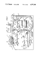
- FIG. 3 is an enlarged view depicting the system for processing image signals together with details of the output scanning apparatus of the machine shown in FIG. 1;
- FIG. 4 is an isometric view showing a stack of documents arranged for scanning with the stack being segregated into individual jobs by job separators with individual jobs further subdivided by page separators;
- FIG. 6 is an enlarged view showing details of the bar code shown in FIG. 5;
- FIG. 7 is a timing chart depicting sampled video from an exemplary bar code and the resulting interrupt signals that are derived therefrom;
- FIG. 8 is a schematic view of logic for reading bar codes on the job and page separators, distinguishing the bar code signals from document image signals, and processing and transmitting the bar code signals to provide programming control signals for a particular job function;
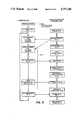
- FIG. 9 is a flow chart depicting overall program flow
- FIG. 11 is a flow chart depicting the Serial I/O initialization routine
- FIGS. 12a and 12b comprise a flow chart depicting the Received Message routine
- FIG. 14 is a flow chart depicting the Serial Port Interrupt Service routine
- FIGS. 15a and 15b comprise a flow chart depicting the Bar and Space Width Measurement routine
- FIG. 16 is a flow chart depicting the Timer Interrupt Service routine
- FIGS. 17a, 17b and 17c comprise a flow chart depicting the Reconstruction Of Character routine
- FIGS. 18a and 18b comprise a flow chart depicting the Parity Check, bit encoding routine
- FIG. 19 is a flow chart depicting the Checksum Verification routine
- FIG. 21 is a flow chart depicting the Exit Procedure.
- a control panel 14 allows the user or operator to select various machine functions and function combinations which the machine is capable of performing such as copy size, copy contrast, number of copies, the manner (duplex, for example) in which the copies are to be made, etc.
- Panel 14 includes programming means in the form of a numeric keyboard 15 ordinarily used by the operator for programming in the number of copies to be made. Other additional selection selectors (not shown) may be provided for programming in various operating features of which machine 5 is capable, such as duplex copying, etc.
- One or more display panels, such as a multi-digit (i.e. eight) numeric display array 18 which displays the number programmed by keyboard 15, are provided for informing the operator of the operating status of machine 5, identifying machine faults, etc.
- a Start/Print button 19 is provided on control panel 14 for starting a machine print cycle.
- operator programming/information devices such as a mouse, touch display, etc. may instead be contemplated either in addition to or in place of the machine programming/information devices described above. Further, as will be understood, operator programming/information devices may be integral with machine 5 or may be separate from and remotely located with respect to machine 5.
- a plurality of sheet transports 31, 32, 33, 34, 35, 36, and 37 which are suitably driven from main drive motor 29, cooperate with suitable sheet guides to form a paper path through which the copy sheets 21, drawn from either main or auxiliary paper supply trays 27 or 27', or from duplex paper supply tray 28, pass during processing. Finished copies are output by gate 38 to either top tray 39 or through a discharge path 30 to an external copy sheet handler such as a sorter (not shown). Suitable copy sheet sensors are provided at discrete points along the copy sheet path to provide control information and identify sheet jams.
- the latent electrostatic image formed on the photoconductive surface of photoreceptor 22 is developed at a developing station C by means of a pair of magnetic brush developer rollers 40, 41 which bring a suitable developer material into contact with the electrostatic latent image.
- the latent image attracts toner particles from the carrier granules of the developer material to form a toner powder image on the photoconductive surface of belt 22.
- the developed image is transferred to a copy sheet 21 at transfer station D following which the copy sheet is transported to fusing station E where the developed image is permanently fixed on the copy sheet by cooperating heated fuser roller 42 and backup roller 44.
- Input scanner section 7 employs one or more linear scanning arrays 60 which may for example comprise charge couple devices (CCD) supported below and in scanning relation to a transparent platen 62 by a carriage 64.
- Carriage 64 is in turn supported for reciprocating movement along a path paralleling platen 62 by rails 63.
- a drive screw 65 serves to move carriage 64 along rails 63, screw 65 being driven by a reversible motor 66 which selectively moves carriage 64 in either a forward or reverse scanning direction.
- a suitable lens 68 is provided to focus array 60 on a line-like segment of platen 62 and the document 70 resting thereon.
- a suitable lamp 71 illuminates the document line being scanned.
- Array 60 provides electrical image signals or pixels representative of the document image scanned which, after suitable processing, are input to a suitable memory where the signals are stored pending use.
- the image signals may be used for purposes other than printing copies, as for example, the signals may be sent via a communication channel (not shown) to another location, or stored, etc.
- Documents 70 to be scanned are brought from a document tray 88 forward by the document handler section 10 into position on platen 62 for scanning. Following scanning, the document handler returns the documents back to the document stack in the document tray 88.
- Machine controller section 9 which controls operation of machine 5, has one or more microprocessors 55 together with suitable memory, 56 for storing machine operating programs and operator program instructions.
- the various operating components and sections of machine 5 are linked together as by means of communication channel 57.
- raster output scanner section 8 includes a suitable source of high intensity light such as laser 77 modulated in accordance with the content of the image signals as by an acousto-optic modulator 78 to provide zero and first order imaging beams 80, 81.
- Beam 80 is impinged against a beam stop 83 while beam 81 is scanned across photoreceptor 22 at exposure station B by a scanning polygon 84 to expose the previously charged photoreceptor and create a latent electrostic image of the document represented by the image signals input to modulator 78.
- Suitable optical means such as lens 85 is provided to focus beam 81 on photoreceptor 22.
- control sheets in the form of special documents are employed to segregate selected ones of the documents 70 in document handler 10 from one another and to input control or programming instructions to machine 5 for the particular documents associated with each control sheet. More specifically, the documents 70 in document handler 10 are batched, each batch 125 representing a particular job for machine 5. Batches 125 are segregated from one another by control sheets which are referred to herein as job separators 127, separators 127 bearing machine readable data in the form of an optically detectable code such as bar code 130 identifying the specific job to be performed by machine 5 on the batch 125 of documents with which the job separator 127 is associated.
- job separators 127 separators 127 bearing machine readable data in the form of an optically detectable code such as bar code 130 identifying the specific job to be performed by machine 5 on the batch 125 of documents with which the job separator 127 is associated.
- Job exceptions which represent a change in the programming parameters for one or more documents in a job batch 125, are handled by special documents termed page separators 129.
- Page separators 129 similarly bear machine readable data in the form of code 130, separators 129 typically providing control instructions which cause the machine 5 to process one or more documents within a batch 125 in a manner different from or as an exception to the rest of the batch.
- the machine reverts back to processing the remaining documents of the batch in accordance with the control instructions of the job separator 127 for that particular batch until either the end of the batch is reached or another page separator 129 is encountered.
- page separators 129 can be programmed to interrupt further machine operation for the purpose of allowing the operator to intervene. Such operator intervention may be for the purpose of processing an oversized document such as a large drawing, or processing a book, etc.
- the bar codes on separators 127, 129 when scanned by array 60, provide image signals identifying the specific job program represented by the job or page separator 127, 129 being scanned.
- the coded information on job and page separators 127, 129 respectively vary with different job programs, with the appropriate separator 127 or 129 being matched with the specific job program desired, and located within the document stack at the proper point.
- the operator When using job and page separators, the operator first programs the particular job or job exception into the machine through the machine controller illustrated here by control panel 14 where the job program is stored in the machine memory.
- a specific job identifier (e.g., a job number) which is the same as that represented by the image appearing on the job or page separator after decoding is also input to the machine by the operator with the job.
- the job or page separator is then placed, i.e., interleaved, with the documents at the correct position in the document tray 88.
- the image signals are decoded and matched with the job identifier previously programmed into the machine.
- the machine then operates under the previously input job program instructions to carry out the job or job exception.
- job and page separators 127, 129 are placed in tray 88 so as to be scanned ahead of the document or documents that are associated with the job or job exception represented by the individual separators.
- separators 127, 129 By using job and page separators 127, 129 and the machine controller, the operator is able to pre-program different jobs which can be stacked in the document handler tray 88 at the same time. Since the present invention allows the job and page separators to be detected, read, and to be correlated or cross-referenced to pre-programmed machine features and functions, the machine controller 9, to which the control instructions derived from scanning a job and/or page separator interleaved with documents in tray 88 are input, can identify and separate jobs and electronically respond to different job parameters. As a result, separators 127, 129 provide a means for pre-programmed job batching and input batching, enhancing machine productivity and throughput. Additional uses for separators 127, 129 may be envisioned such as customer billing, user identification, etc.
- Job and page separators may be generated by printing machine 5 itself or other suitable offsite devices capable of generating bar codes compatible with machine 5 may be used. Further, printing machine 5 or some other suitable bar code generating device may be used to in effect create one or more master job and/or sheet separators representing various job and exception programs which may then be reproduced as needed.
- Job and page separators 127, 129 preferably comprise a sheet 132 having in the body thereof visual and readable information 135 which allows the operator to read and determine the job identifier (e.g., the job number) represented by the bar code 130 thereon.
- the various job functions which the operator may select i.e., paper tray to be used, number of prints, etc.
- separators 127, 129 are also printed on separators 127, 129 to allow the operator, when inputting the job program to the machine 5, to mark or write (i.e., as by checking off) the particular job programmed.
- each bar code 130 is preferably placed at several points on sheet 132, i.e.
- the bar codes 130 are preferably placed on both sides of the sheet 132.
- Job and page separators 127, 129 are brought by document handler 10 to platen 62 and located thereon in the same manner as are documents 70.
- Separators 127, 129 are optically scanned by array 60 in the same manner as are the documents 70.
- the image signals obtained by array 60 from scanning the bar code on separators 127, 129 are discriminated from the image signals obtained by scanning the documents 70, decoded, and the resulting control data input to the machine controller as will appear.
- the exemplary code 130 shown and described herein provides a pre-programmed list of job/page parameters that are referenced to a five digit number, termed a ⁇ matrix 2 of 5 code ⁇ .
- the ⁇ matrix 2 of 5 code ⁇ is composed of a series of wide and narrow black bars 140, 141 respectively and intervening wide and narrow white spaces 144, 145 therebetween.
- a wide bar narrow white spaces 144, 145 therebetween In this code type, a wide bar 140 or wide space 144 is used to represent a binary "1" while a narrow bar 141 or space 145 is used to represent a binary "0".
- Characteristics of this type code include 3 black spaces for each character, inter-character spaces, an even parity bit, a checksum character, and a unique start and stop pattern. Each character is five bits, with the least significant bit on the left (as shown in the drawing) and the parity bit following the most significant bit.
- One complete bar code 130 consists of a start pattern 147, five message characters 148, and a checksum character 149 followed by a stop pattern 150.
- code 130 can encode up to 100,000 unique numbers.
- the bulk of decoding the bar code is done in software, minimizing hardware requirements.
- the prime function of the hardware (shown in FIG. 8) is to sense the black-to-white and white-to-black transitions within the bar code. Sampling is done only in a specific section of each coded separator 127, 129, preferably, in the approximate center of the bar code 130. In the exemplary arrangement shown, the sampling width is a block 5 pixels wide as shown at 131 in FIG. 6.
- one pixel of scanned video is used for decoding.
- each block of pixels 131 is averaged to provide the one pixel sample per scanline.
- the pixels are input to a suitable serial to parallel converter 152, the output of which is fed to a 5-bit encoder 154 which averages the block of pixels to provide one bit (i.e. either a "1" or "0") to flip flop 155.
- a pixel counter 175 with decoding logic 176 is provided.
- Decoding logic 176 is programmed to provide an enabling signal (END SAMPLE) to flip flop 155 when counter 175 reaches a preset start scan count representing the first pixel sample of block 131 and to disable flip flop 155 when the count on counter 175 reaches a preset end scan count.
- flip flop 155 passes the pixel output of encoder 154 to a suitable transition sensor 158 such as a dual monostable multi-vibrator.
- transition sensor 158 outputs a low pulse signal 159 at each transition from "1" to "0” (i.e. from black-to-white) and from “0" to "1” (i.e. from white-to-black) in the signal input from flip flop 155 to provide interrupt signals 162.
- Signals 162, which serve as an external interrupt are input to a microcontroller chip 160 such as an Intel Model 8051 microcontroller.
- chip 160 is programmed with decoding software which identifies the presence of a job or page separator 127, 129 bearing bar code 130. Where a coded separator 127, 129 is present, the bar code 130 is decoded to provide program control signals to the machine controller section 9. In this process, the software measures the time between interrupts to distinguish wide and narrow bars 140, 141 and spaces 144, 145 from one another, thus decoding the interrupts into binary "1's" and "0's”.
- I/O ports 165, 166, 167, 168 of microcontroller chip 160 are used for data transmission, with port 165 being for input of the interrupt signals 162 from transition sensor 158 to chip 160, port 166 for outputting serial data from chip 160 via a universal asynchronous receiver-transmitter (UART) 164 to the machine controller section 9, port 167 for inputting serial data from the machine controller section 9 via receiver-transmitter 164 to chip 160, and port 168 for inputting enabling Clear To Send (CTS) signals to chip 160 from receiver-transmitter 164.
- UART universal asynchronous receiver-transmitter
- CTS Clear To Send
- Receiver-transmitter 164 converts serial data output of chip 160 from port 166 to parallel data that can be read by the machine controller section 9 and converts parallel data from controller section 9 to asynchronous serial data for transmission back to chip 160 through port 167.
- An additional port 169 receives a page condition (Page Active) signal from the machine controller section allowing chip 160 to know when to begin processing.
- the chip interrupt service routine and chip on-board timers 170 and 171 and RAM buffer 174 handle data transfer timing.
- the characters in the bar code 130 are reconstructed by converting the width counts to binary values of "1" or "0" based on whether the width is greater than or less than a threshold value T.
- the counts stored in buffer 174 are compared with a threshold T which is continuously updated to compensate for differences in scanning speed as well as random errors such as video noise or copy quality defects within the scanned code by averaging the width counts of the last logic "0" and logic "1".
- the five message characters are then converted to standard 7 bit ASCII format plus an even parity bit by adding a constant of 30 HEX to the weighted sum of each character's bits.
- the five ASCII message characters are transmitted serially to the machine controller.
- Decoding software also performs the tasks of recognizing start and stop patterns 147, 150 in the bar code, error checking including a parity check on each character, a checksum character check, and serial transmission of the decoded message to the machine controller section in standard 7 bit ASCII plus even parity format.
- a wait loop (Wait for end of page, poll serial reception) is entered waiting until the end of the current scanned page.
- This loop is held until the end of the current page following which a second wait loop (Wait for start of page, poll serial reception) is entered waiting for an active page to begin processing.
- communication port 169 of chip 160 is polled for serial reception of a message (Active Page?).
- the loop is exited, the timer 170 interrupt enabled (Timer 170 Interrupt Service--FIG. 16), and the "Call Width Count" routine (FIGS. 15a,b and c) is entered.
- timer 170 which functions as a variable count timer, is initialized to zero and to operate as an 8-bit auto-reload counter set to over flow every 100 usec.
- the address (I) of buffer 174 which functions as a count buffer, is initialized to zero.
- Timer 170 is turned on and a loop test variable is initialized.
- a loop (COUNT LOOP) is made until the width of the start margin is checked to determine if there is a bar code 130 present on the page, or if the count buffer 174 has filled up, or if a valid bar code end margin has been identified.
- the loop is interrupted by an external interrupt on each video transition 159 or on each overflow of timer 170 on expiration of the 100 usec. interval.
- the count buffer 174 contains time interval counts representing the widths of the bars 140, 141 and spaces 144, 145 in the entire message from the "Width Count" routine.
- a check is made to see if the start margin detected is too wide by comparing the count in the count buffer with a preselected number (Temp Cnt>46?). If so, the EXIT routine (FIG. 21) is called and the message "No Bar Code" sent.
- the message characters are then reconstructed by converting the width counts to binary values of 1 or 0.
- the counts are sorted into wide and narrow elements depending on whether their width is greater than or less than a threshold value (Next$Cnt>T?).
- the bar code start 147 (1st Char) and stop 150 (CHR$Cnt>6) character are verified (i.e. Start Char. Verify). If either the start or stop the characters do not verify, the routine is exited (Call Exit) and the message "No Bar Code" sent.
- the Send Message routine (FIG. 13) is called.
- the message is saved in case re-transmission is needed.
- a wait loop is entered while polling the port bit 169 for a CTS signal from receiver/transmitter 164. When the CTS signal goes low, the message is transmitted from port 166 to the machine controller section 9 via receiver/transmitter 162. Then a loop is entered testing a test variable which will be set false by occurrence of the Serial Interrupt Service Routine, indicating the end of the character has been sent.
Abstract
Description
Claims (19)
Priority Applications (2)
| Application Number | Priority Date | Filing Date | Title |
|---|---|---|---|
| US06/931,484 US4757348A (en) | 1986-11-17 | 1986-11-17 | High speed electronic reprographic/printing machine |
| JP62284082A JPS63139467A (en) | 1986-11-17 | 1987-11-10 | High speed electronic copier/printer |
Applications Claiming Priority (1)
| Application Number | Priority Date | Filing Date | Title |
|---|---|---|---|
| US06/931,484 US4757348A (en) | 1986-11-17 | 1986-11-17 | High speed electronic reprographic/printing machine |
Publications (1)
| Publication Number | Publication Date |
|---|---|
| US4757348A true US4757348A (en) | 1988-07-12 |
Family
ID=25460850
Family Applications (1)
| Application Number | Title | Priority Date | Filing Date |
|---|---|---|---|
| US06/931,484 Expired - Lifetime US4757348A (en) | 1986-11-17 | 1986-11-17 | High speed electronic reprographic/printing machine |
Country Status (2)
| Country | Link |
|---|---|
| US (1) | US4757348A (en) |
| JP (1) | JPS63139467A (en) |
Cited By (84)
| Publication number | Priority date | Publication date | Assignee | Title |
|---|---|---|---|---|
| US4847656A (en) * | 1987-04-16 | 1989-07-11 | Ricoh Company, Ltd. | Method and apparatus for controlling copying operation |
| US4876571A (en) * | 1987-04-11 | 1989-10-24 | Ricoh Company, Ltd. | Copying machine having a bar code reader |
| US4970554A (en) * | 1988-10-24 | 1990-11-13 | Xerox Corporation | Job processing system for high speed electronic copying/printing machines |
| US4987447A (en) * | 1989-09-18 | 1991-01-22 | Eastman Kodak Company | Control sheet generation for copiers and printers |
| US5053814A (en) * | 1986-12-24 | 1991-10-01 | Minolta Camera Kabushiki Kaisha | Image forming apparatus |
| US5060980A (en) * | 1990-05-30 | 1991-10-29 | Xerox Corporation | Form utilizing encoded indications for form field processing |
| US5067835A (en) * | 1989-11-27 | 1991-11-26 | Brother Kogyo Kabushiki Kaisha | Printing apparatus |
| US5081494A (en) * | 1990-06-15 | 1992-01-14 | Xerox Corporation | Job supplement for electronic printing machines |
| EP0478355A2 (en) * | 1990-09-28 | 1992-04-01 | Xerox Corporation | Electronic reprographic systems |
| EP0478336A2 (en) * | 1990-09-28 | 1992-04-01 | Xerox Corporation | Document imaging system |
| US5119213A (en) * | 1990-07-27 | 1992-06-02 | Xerox Corporation | Scanner document absence code system |
| US5119472A (en) * | 1990-12-10 | 1992-06-02 | Fuji Xerox Co., Ltd. | Printer control device |
| US5124748A (en) * | 1990-10-10 | 1992-06-23 | Fuji Xerox Co., Ltd. | Picture image processing system |
| US5126858A (en) * | 1990-10-10 | 1992-06-30 | Fuji Xerox Co., Ltd. | Picture image processing system |
| EP0508098A2 (en) * | 1991-03-11 | 1992-10-14 | Sharp Kabushiki Kaisha | Image forming apparatus |
| US5168371A (en) * | 1990-12-14 | 1992-12-01 | Fuji Xerox Co., Ltd. | Image processing system for generating, storing, and transmitting image datafiles associated with enciphered identification information |
| EP0523634A2 (en) * | 1991-07-15 | 1993-01-20 | Canon Kabushiki Kaisha | Image processing apparatus being capable of setting processing mode by sheet for setting processing mode |
| US5207412A (en) * | 1991-11-22 | 1993-05-04 | Xerox Corporation | Multi-function document integrater with control indicia on sheets |
| EP0547788A1 (en) | 1991-12-16 | 1993-06-23 | Xerox Corporation | Removable set retaining system for copy sheets |
| US5225900A (en) * | 1990-12-31 | 1993-07-06 | Xerox Corporation | Method of storing information within a reproduction system |
| US5243381A (en) * | 1993-01-04 | 1993-09-07 | Xerox Corporation | Method for compiling multiple jobs with job reference sheets |
| US5247371A (en) * | 1990-10-10 | 1993-09-21 | Fuji Xerox Co., Ltd. | Image processing system using job control sheets with attributes |
| US5272511A (en) * | 1992-04-30 | 1993-12-21 | Xerox Corporation | Sheet inserter and methods of inserting sheets into a continuous stream of sheets |
| US5331140A (en) * | 1992-04-02 | 1994-07-19 | Xerox Corporation | Code reading systems |
| US5506663A (en) * | 1994-11-07 | 1996-04-09 | Xerox Corporation | Scanner mounting apparatus for an electrostatographic printing machine |
| US5534975A (en) * | 1995-05-26 | 1996-07-09 | Xerox Corporation | Document processing system utilizing document service cards to provide document processing services |
| US5563966A (en) * | 1991-11-22 | 1996-10-08 | Hitachi, Ltd. | Method and apparatus for processing coded image data |
| WO1996041463A1 (en) * | 1995-06-07 | 1996-12-19 | Geshwind David M | A method for utilizing point-to-point communication devices including fax machines as bi-directional internet terminals |
| US5608493A (en) * | 1994-06-07 | 1997-03-04 | Sharp Kabushiki Kaisha | Image forming apparatus capable of setting an operational mode by reading image of a predetermined format |
| US5640647A (en) * | 1995-11-27 | 1997-06-17 | Xerox Corporation | Method and apparatus for selectively scanning pages within a document stack |
| US5644408A (en) * | 1990-01-05 | 1997-07-01 | Symbol Technologies, Inc. | Apparatus for processing human-readable and machine-readable documents |
| US5710874A (en) * | 1995-10-25 | 1998-01-20 | Xerox Corporation | System for managing printing system memory with machine readable code |
| US5715380A (en) * | 1995-08-14 | 1998-02-03 | Samsung Electronics Co., Ltd. | Image forming apparatus and multiuser identification printing method therefor |
| US5794099A (en) * | 1994-11-22 | 1998-08-11 | Eastman Kodak Company | Copier apparatus and method with flexible source document entry scanning with display of options for selection of source |
| US5848325A (en) * | 1996-05-16 | 1998-12-08 | Ricoh Company, Ltd. | Image forming apparatus |
| US5901224A (en) * | 1996-10-21 | 1999-05-04 | Xerox Corporation | Quasi-reprographics with variable embedded data with applications to copyright management, and distribution control |
| EP0929176A2 (en) * | 1998-01-08 | 1999-07-14 | Xerox Corporation | Recognizing job separator pages in a document scanning device |
| US5974202A (en) * | 1990-01-05 | 1999-10-26 | Symbol Technologies, Inc. | Apparatus and method for processing a machine readable document with embedded machine instructions |
| US6000621A (en) * | 1995-12-21 | 1999-12-14 | Xerox Corporation | Tilings of mono-code and dual-code embedded data pattern strips for robust asynchronous capture |
| US6002491A (en) * | 1990-01-05 | 1999-12-14 | Symbol Technologies, Inc. | Apparatus for processing human-readable and machine-readable documents |
| US6043899A (en) * | 1997-03-24 | 2000-03-28 | Olympus Optical Co., Ltd. | Code pattern image recording apparatus |
| US6118544A (en) * | 1996-12-26 | 2000-09-12 | Kabushiki Kaisha Toshiba | Image forming apparatus for processing according to separation sheet |
| US6188430B1 (en) * | 1997-04-18 | 2001-02-13 | Canon Kabushiki Kaisha | Digital camera and ink-jet printing apparatus |
| US6295144B1 (en) * | 1997-05-08 | 2001-09-25 | Samsung Electronics Co., Ltd. | Pre-scanning method and apparatus for shuttle scanning system |
| US6563598B1 (en) | 1999-09-07 | 2003-05-13 | Hewlett-Packard Development Company, L.P. | Method and apparatus for digital document control |
| US6666605B2 (en) | 2000-12-20 | 2003-12-23 | Xerox Corporation | Method for improved security in the handling of printer bin output |
| US20040050854A1 (en) * | 2002-09-13 | 2004-03-18 | Avery Dennison Corporation | Versatile label sheet and dispenser |
| US20040050497A1 (en) * | 2002-09-13 | 2004-03-18 | Avery Dennison Corporation | Versatile label sheet and dispenser |
| US6734999B1 (en) * | 1996-12-24 | 2004-05-11 | Minolta Co., Ltd. | Image forming apparatus and image forming method |
| DE10315449A1 (en) * | 2003-04-04 | 2004-10-14 | Heidelberger Druckmaschinen Ag | Method for sequence control of a device for handling sheet-like printing materials |
| US6957025B1 (en) * | 2004-05-17 | 2005-10-18 | Xerox Corporation | Ordered sets printing with automatic dual trays sheet feeding |
| JP2006174462A (en) * | 2004-12-17 | 2006-06-29 | Ricoh Co Ltd | Method and apparatus for information processing |
| US20060228137A1 (en) * | 2005-04-12 | 2006-10-12 | Xerox Corporation | Multiple quantity print job separation systems and methods |
| US20060285126A1 (en) * | 2005-06-17 | 2006-12-21 | Xerox Corporation | Machine setup by scanning a configuration sheet |
| US20070002388A1 (en) * | 2000-03-28 | 2007-01-04 | Mongonet | Method and system for transferring sponsored digitized representations of documents via computer network transfer protocols |
| US20070008574A1 (en) * | 2000-03-28 | 2007-01-11 | Mongonet | Method and system for transferring digitized representations of documents via computer network transfer protocols |
| US20070024899A1 (en) * | 2000-03-28 | 2007-02-01 | Mongonet | Method and system for combining separate digitized representations of documents for retransmission via computer network transfer protocols |
| US7180638B1 (en) | 2000-02-16 | 2007-02-20 | Ricoh Co., Ltd. | Network fax machine using a web page as a user interface |
| US20070133040A1 (en) * | 2005-12-07 | 2007-06-14 | Xerox Corporation | System and method for forming a cluster of networked devices |
| US20070168557A1 (en) * | 2000-03-28 | 2007-07-19 | Mongonet | Fax-to-email and email-to-fax communication system and method |
| US20070194101A1 (en) * | 1994-05-25 | 2007-08-23 | Rathus Spencer A | Method and apparatus for accessing electronic data via a familiar printed medium |
| US20070223051A1 (en) * | 2000-03-28 | 2007-09-27 | Mongonet | Method and system for modified document transfer via computer network transfer protocols |
| US20070229889A1 (en) * | 2000-03-28 | 2007-10-04 | Mongonet | Method and system for pay per use document transfer via computer network transfer protocols |
| US20070229890A1 (en) * | 2000-03-28 | 2007-10-04 | Mongonet | Methods and apparatus for manipulating and providing facsimile transmissions to electronic storage destinations |
| US20070236749A1 (en) * | 2000-03-28 | 2007-10-11 | Mongonet | Methods and apparatus for authenticating facsimile transmissions to electronic storage destinations |
| US20070237314A1 (en) * | 2000-03-28 | 2007-10-11 | Mongonet | Method and system for entry of electronic data via fax-to-email communication |
| US20070236750A1 (en) * | 2000-03-28 | 2007-10-11 | Mongonet | Methods and apparatus for facilitating facsimile transmissions to electronic storage destinations |
| US20070236732A1 (en) * | 2000-03-28 | 2007-10-11 | Mongo Net | Methods and apparatus for compositing facsimile transmissions to electronic storage destinations |
| US20080130040A1 (en) * | 2000-03-28 | 2008-06-05 | Mongonet | Methods and apparatus for facsimile transmissions to electronic storage destinations including tracking data |
| US7404521B2 (en) | 2004-12-23 | 2008-07-29 | Pitney Bowes Inc. | Paper based mailing and shipping user interface |
| US20080212144A1 (en) * | 2000-03-28 | 2008-09-04 | Mongonet | Methods and apparatus for secure facsimile transmissions to electronic storage destinations |
| US20090034701A1 (en) * | 2000-03-28 | 2009-02-05 | Mongonet | Methods and apparatus for billing of facsimile transmissions to electronic storage destinations |
| US20090059310A1 (en) * | 2000-03-28 | 2009-03-05 | Mongonet | Methods and apparatus for facsimile transmissions to electronic storage destinations including embedded barcode fonts |
| US20090086289A1 (en) * | 2007-10-02 | 2009-04-02 | Brother Kogyo Kabushiki Kaisha | Image reading device |
| US20090206153A1 (en) * | 2008-02-20 | 2009-08-20 | Xerox Corporation | Multi-job feeder apparatus and method |
| US20090304430A1 (en) * | 2008-06-04 | 2009-12-10 | Xerox Corporation | Multi-job feeder system |
| US20100042523A1 (en) * | 2008-07-25 | 2010-02-18 | Mongonet | Sponsored Facsimile to E-Mail Transmission Methods and Apparatus |
| US20100141985A1 (en) * | 2006-11-18 | 2010-06-10 | Amir Noy | Print Job Separation |
| US20100177339A1 (en) * | 2009-01-12 | 2010-07-15 | Xerox Corporation | Robust insert page method using code pages |
| US20110192894A1 (en) * | 2010-02-09 | 2011-08-11 | Xerox Corporation | Method for one-step document categorization and separation |
| US8261993B2 (en) | 1994-05-25 | 2012-09-11 | Marshall Feature Recognition, Llc | Method and apparatus for accessing electronic data via a familiar printed medium |
| US8910876B2 (en) | 1994-05-25 | 2014-12-16 | Marshall Feature Recognition, Llc | Method and apparatus for accessing electronic data via a familiar printed medium |
| WO2017174778A1 (en) * | 2016-04-08 | 2017-10-12 | Sas Sages Informatique | Method and system for separating documents during batch digitization |
| US20200238727A1 (en) * | 2019-01-28 | 2020-07-30 | Kyocera Document Solutions, Inc. | Marking An Organization Of Papers |
Families Citing this family (4)
| Publication number | Priority date | Publication date | Assignee | Title |
|---|---|---|---|---|
| JP2523898B2 (en) * | 1988-10-24 | 1996-08-14 | ゼロックス コーポレーション | Original print job processing method |
| CA2039652C (en) * | 1990-05-30 | 1996-12-24 | Frank Zdybel, Jr. | Hardcopy lossless data storage and communications for electronic document processing systems |
| JPH07295958A (en) * | 1994-04-27 | 1995-11-10 | Ricoh Co Ltd | Paper media system |
| JP5922662B2 (en) | 2011-08-22 | 2016-05-24 | 積水化学工業株式会社 | Reefer container and power supply system to reefer container |
Citations (8)
| Publication number | Priority date | Publication date | Assignee | Title |
|---|---|---|---|---|
| US3687256A (en) * | 1970-04-15 | 1972-08-29 | Ncr Co | Optical bar code parallel printer |
| US3936182A (en) * | 1974-08-12 | 1976-02-03 | Xerox Corporation | Control arrangement for an electrostatographic reproduction apparatus |
| US3986449A (en) * | 1970-11-24 | 1976-10-19 | Monarch Marking Systems, Inc. | Selective printing apparatus |
| US4248528A (en) * | 1979-04-04 | 1981-02-03 | Xerox Corporation | Copier with document sensing control |
| US4494862A (en) * | 1980-09-30 | 1985-01-22 | Minolta Camera Kabushiki Kaisha | Computerized information processing system equipped with copying apparatus |
| JPS6052863A (en) * | 1983-09-02 | 1985-03-26 | Fuji Xerox Co Ltd | Job setter |
| US4602776A (en) * | 1984-10-22 | 1986-07-29 | Xerox Corporation | Insertion apparatus for use with copier/sorter system |
| US4609283A (en) * | 1983-12-26 | 1986-09-02 | Minolta Camera Kabushiki Kaisha | Copying apparatus with preprogrammed features enabled by a document |
Family Cites Families (1)
| Publication number | Priority date | Publication date | Assignee | Title |
|---|---|---|---|---|
| JPS6135060A (en) * | 1984-07-27 | 1986-02-19 | Canon Inc | Image processor |
-
1986
- 1986-11-17 US US06/931,484 patent/US4757348A/en not_active Expired - Lifetime
-
1987
- 1987-11-10 JP JP62284082A patent/JPS63139467A/en active Pending
Patent Citations (8)
| Publication number | Priority date | Publication date | Assignee | Title |
|---|---|---|---|---|
| US3687256A (en) * | 1970-04-15 | 1972-08-29 | Ncr Co | Optical bar code parallel printer |
| US3986449A (en) * | 1970-11-24 | 1976-10-19 | Monarch Marking Systems, Inc. | Selective printing apparatus |
| US3936182A (en) * | 1974-08-12 | 1976-02-03 | Xerox Corporation | Control arrangement for an electrostatographic reproduction apparatus |
| US4248528A (en) * | 1979-04-04 | 1981-02-03 | Xerox Corporation | Copier with document sensing control |
| US4494862A (en) * | 1980-09-30 | 1985-01-22 | Minolta Camera Kabushiki Kaisha | Computerized information processing system equipped with copying apparatus |
| JPS6052863A (en) * | 1983-09-02 | 1985-03-26 | Fuji Xerox Co Ltd | Job setter |
| US4609283A (en) * | 1983-12-26 | 1986-09-02 | Minolta Camera Kabushiki Kaisha | Copying apparatus with preprogrammed features enabled by a document |
| US4602776A (en) * | 1984-10-22 | 1986-07-29 | Xerox Corporation | Insertion apparatus for use with copier/sorter system |
Non-Patent Citations (2)
| Title |
|---|
| Noyes, "Transparent Carrier for Entry of Job Control Information in Copier", IBM Disclosure Bulletin, 2/76, pp. 2808-2809. |
| Noyes, Transparent Carrier for Entry of Job Control Information in Copier , IBM Disclosure Bulletin, 2/76, pp. 2808 2809. * |
Cited By (130)
| Publication number | Priority date | Publication date | Assignee | Title |
|---|---|---|---|---|
| US5053814A (en) * | 1986-12-24 | 1991-10-01 | Minolta Camera Kabushiki Kaisha | Image forming apparatus |
| US4876571A (en) * | 1987-04-11 | 1989-10-24 | Ricoh Company, Ltd. | Copying machine having a bar code reader |
| US4847656A (en) * | 1987-04-16 | 1989-07-11 | Ricoh Company, Ltd. | Method and apparatus for controlling copying operation |
| US4970554A (en) * | 1988-10-24 | 1990-11-13 | Xerox Corporation | Job processing system for high speed electronic copying/printing machines |
| US4987447A (en) * | 1989-09-18 | 1991-01-22 | Eastman Kodak Company | Control sheet generation for copiers and printers |
| US5067835A (en) * | 1989-11-27 | 1991-11-26 | Brother Kogyo Kabushiki Kaisha | Printing apparatus |
| US5644408A (en) * | 1990-01-05 | 1997-07-01 | Symbol Technologies, Inc. | Apparatus for processing human-readable and machine-readable documents |
| US5760382A (en) * | 1990-01-05 | 1998-06-02 | Symbol Technologies, Inc. | Apparatus for processing human-readable and machine-readable documents |
| US5974202A (en) * | 1990-01-05 | 1999-10-26 | Symbol Technologies, Inc. | Apparatus and method for processing a machine readable document with embedded machine instructions |
| US6002491A (en) * | 1990-01-05 | 1999-12-14 | Symbol Technologies, Inc. | Apparatus for processing human-readable and machine-readable documents |
| US5991469A (en) * | 1990-05-30 | 1999-11-23 | Xerox Corporation | System for reading a form utilizing encoded indications for form field processing |
| US5060980A (en) * | 1990-05-30 | 1991-10-29 | Xerox Corporation | Form utilizing encoded indications for form field processing |
| US5081494A (en) * | 1990-06-15 | 1992-01-14 | Xerox Corporation | Job supplement for electronic printing machines |
| US5119213A (en) * | 1990-07-27 | 1992-06-02 | Xerox Corporation | Scanner document absence code system |
| EP0478355A2 (en) * | 1990-09-28 | 1992-04-01 | Xerox Corporation | Electronic reprographic systems |
| EP0478355A3 (en) * | 1990-09-28 | 1993-09-08 | Xerox Corporation | Electronic reprographic systems |
| US5513017A (en) * | 1990-09-28 | 1996-04-30 | Xerox Corporation | Automatic document imaging mode selection system |
| EP0478336A2 (en) * | 1990-09-28 | 1992-04-01 | Xerox Corporation | Document imaging system |
| EP0478336A3 (en) * | 1990-09-28 | 1992-08-19 | Xerox Corporation | Document imaging system |
| JP2967309B2 (en) | 1990-10-10 | 1999-10-25 | 富士ゼロックス株式会社 | Image processing device |
| US5126858A (en) * | 1990-10-10 | 1992-06-30 | Fuji Xerox Co., Ltd. | Picture image processing system |
| US5124748A (en) * | 1990-10-10 | 1992-06-23 | Fuji Xerox Co., Ltd. | Picture image processing system |
| US5247371A (en) * | 1990-10-10 | 1993-09-21 | Fuji Xerox Co., Ltd. | Image processing system using job control sheets with attributes |
| US5119472A (en) * | 1990-12-10 | 1992-06-02 | Fuji Xerox Co., Ltd. | Printer control device |
| US5168371A (en) * | 1990-12-14 | 1992-12-01 | Fuji Xerox Co., Ltd. | Image processing system for generating, storing, and transmitting image datafiles associated with enciphered identification information |
| US5301044A (en) * | 1990-12-31 | 1994-04-05 | Xerox Corporation | Marking material containing a taggant, and method of producing an image |
| US5225900A (en) * | 1990-12-31 | 1993-07-06 | Xerox Corporation | Method of storing information within a reproduction system |
| EP0508098A2 (en) * | 1991-03-11 | 1992-10-14 | Sharp Kabushiki Kaisha | Image forming apparatus |
| US5296896A (en) * | 1991-03-11 | 1994-03-22 | Sharp Kabushiki Kaisha | Image forming apparatus with storage for copying conditions |
| EP0508098A3 (en) * | 1991-03-11 | 1993-02-24 | Sharp Kabushiki Kaisha | Image forming apparatus |
| EP0523634A2 (en) * | 1991-07-15 | 1993-01-20 | Canon Kabushiki Kaisha | Image processing apparatus being capable of setting processing mode by sheet for setting processing mode |
| EP0523634A3 (en) * | 1991-07-15 | 1993-03-17 | Canon Kabushiki Kaisha | Image processing apparatus being capable of setting processing mode by sheet for setting processing mode |
| US5235396A (en) * | 1991-07-15 | 1993-08-10 | Canon Kabushiki Kaisha | Image processing apparatus having an image processing mode selected by a special sheet |
| US5207412A (en) * | 1991-11-22 | 1993-05-04 | Xerox Corporation | Multi-function document integrater with control indicia on sheets |
| US5563966A (en) * | 1991-11-22 | 1996-10-08 | Hitachi, Ltd. | Method and apparatus for processing coded image data |
| EP0547788A1 (en) | 1991-12-16 | 1993-06-23 | Xerox Corporation | Removable set retaining system for copy sheets |
| US5331140A (en) * | 1992-04-02 | 1994-07-19 | Xerox Corporation | Code reading systems |
| US5272511A (en) * | 1992-04-30 | 1993-12-21 | Xerox Corporation | Sheet inserter and methods of inserting sheets into a continuous stream of sheets |
| US5243381A (en) * | 1993-01-04 | 1993-09-07 | Xerox Corporation | Method for compiling multiple jobs with job reference sheets |
| US8910876B2 (en) | 1994-05-25 | 2014-12-16 | Marshall Feature Recognition, Llc | Method and apparatus for accessing electronic data via a familiar printed medium |
| US20070194101A1 (en) * | 1994-05-25 | 2007-08-23 | Rathus Spencer A | Method and apparatus for accessing electronic data via a familiar printed medium |
| US7712668B2 (en) * | 1994-05-25 | 2010-05-11 | Marshall Feature Recognition, Llc | Method and apparatus for accessing electronic data via a familiar printed medium |
| US8261993B2 (en) | 1994-05-25 | 2012-09-11 | Marshall Feature Recognition, Llc | Method and apparatus for accessing electronic data via a familiar printed medium |
| US8261994B2 (en) | 1994-05-25 | 2012-09-11 | Marshall Feature Recognition, Llc | Method and apparatus for accessing electronic data via a familiar printed medium |
| US8485445B2 (en) | 1994-05-25 | 2013-07-16 | Marshall Feature Recognition, Llc | Method and apparatus for accessing electronic data via a familiar printed medium |
| US5608493A (en) * | 1994-06-07 | 1997-03-04 | Sharp Kabushiki Kaisha | Image forming apparatus capable of setting an operational mode by reading image of a predetermined format |
| US5506663A (en) * | 1994-11-07 | 1996-04-09 | Xerox Corporation | Scanner mounting apparatus for an electrostatographic printing machine |
| US5794099A (en) * | 1994-11-22 | 1998-08-11 | Eastman Kodak Company | Copier apparatus and method with flexible source document entry scanning with display of options for selection of source |
| US5534975A (en) * | 1995-05-26 | 1996-07-09 | Xerox Corporation | Document processing system utilizing document service cards to provide document processing services |
| WO1996041463A1 (en) * | 1995-06-07 | 1996-12-19 | Geshwind David M | A method for utilizing point-to-point communication devices including fax machines as bi-directional internet terminals |
| US5715380A (en) * | 1995-08-14 | 1998-02-03 | Samsung Electronics Co., Ltd. | Image forming apparatus and multiuser identification printing method therefor |
| US5710874A (en) * | 1995-10-25 | 1998-01-20 | Xerox Corporation | System for managing printing system memory with machine readable code |
| US5640647A (en) * | 1995-11-27 | 1997-06-17 | Xerox Corporation | Method and apparatus for selectively scanning pages within a document stack |
| US6000621A (en) * | 1995-12-21 | 1999-12-14 | Xerox Corporation | Tilings of mono-code and dual-code embedded data pattern strips for robust asynchronous capture |
| US5848325A (en) * | 1996-05-16 | 1998-12-08 | Ricoh Company, Ltd. | Image forming apparatus |
| US5901224A (en) * | 1996-10-21 | 1999-05-04 | Xerox Corporation | Quasi-reprographics with variable embedded data with applications to copyright management, and distribution control |
| US6734999B1 (en) * | 1996-12-24 | 2004-05-11 | Minolta Co., Ltd. | Image forming apparatus and image forming method |
| US6118544A (en) * | 1996-12-26 | 2000-09-12 | Kabushiki Kaisha Toshiba | Image forming apparatus for processing according to separation sheet |
| US6043899A (en) * | 1997-03-24 | 2000-03-28 | Olympus Optical Co., Ltd. | Code pattern image recording apparatus |
| US6188430B1 (en) * | 1997-04-18 | 2001-02-13 | Canon Kabushiki Kaisha | Digital camera and ink-jet printing apparatus |
| US6295144B1 (en) * | 1997-05-08 | 2001-09-25 | Samsung Electronics Co., Ltd. | Pre-scanning method and apparatus for shuttle scanning system |
| US5978620A (en) * | 1998-01-08 | 1999-11-02 | Xerox Corporation | Recognizing job separator pages in a document scanning device |
| EP0929176A2 (en) * | 1998-01-08 | 1999-07-14 | Xerox Corporation | Recognizing job separator pages in a document scanning device |
| EP0929176A3 (en) * | 1998-01-08 | 2000-10-25 | Xerox Corporation | Recognizing job separator pages in a document scanning device |
| US6563598B1 (en) | 1999-09-07 | 2003-05-13 | Hewlett-Packard Development Company, L.P. | Method and apparatus for digital document control |
| US7180638B1 (en) | 2000-02-16 | 2007-02-20 | Ricoh Co., Ltd. | Network fax machine using a web page as a user interface |
| US7716296B2 (en) | 2000-03-28 | 2010-05-11 | Mongonet | Fax-to-email and email-to-fax communication system and method |
| US8045204B2 (en) | 2000-03-28 | 2011-10-25 | Mongonet | Methods and apparatus for facsimile transmissions to electronic storage destinations including tracking data |
| US8275100B2 (en) | 2000-03-28 | 2012-09-25 | Mongonet | Methods and apparatus for billing of facsimile transmissions to electronic storage destinations |
| US8184318B2 (en) | 2000-03-28 | 2012-05-22 | Mongonet | Methods and apparatus for compositing facsimile transmissions to electronic storage destinations |
| US8045203B2 (en) | 2000-03-28 | 2011-10-25 | Mongonet | Methods and apparatus for secure facsimile transmissions to electronic storage destinations |
| US8035834B2 (en) | 2000-03-28 | 2011-10-11 | Mongonet | Methods and apparatus for manipulating and providing facsimile transmissions to electronic storage destinations |
| US20070002388A1 (en) * | 2000-03-28 | 2007-01-04 | Mongonet | Method and system for transferring sponsored digitized representations of documents via computer network transfer protocols |
| US20070008574A1 (en) * | 2000-03-28 | 2007-01-11 | Mongonet | Method and system for transferring digitized representations of documents via computer network transfer protocols |
| US20070024899A1 (en) * | 2000-03-28 | 2007-02-01 | Mongonet | Method and system for combining separate digitized representations of documents for retransmission via computer network transfer protocols |
| US8023132B2 (en) | 2000-03-28 | 2011-09-20 | Mongonet | Method and system for transferring digitized representations of documents via computer network transfer protocols |
| US8023131B2 (en) | 2000-03-28 | 2011-09-20 | Mongonet | Method and system for combining separate digitized representations of documents for retransmission via computer network transfer protocols |
| US20070168557A1 (en) * | 2000-03-28 | 2007-07-19 | Mongonet | Fax-to-email and email-to-fax communication system and method |
| US7944573B2 (en) | 2000-03-28 | 2011-05-17 | Mongonet | Methods and apparatus for authenticating facsimile transmissions to electronic storage destinations |
| US20070223051A1 (en) * | 2000-03-28 | 2007-09-27 | Mongonet | Method and system for modified document transfer via computer network transfer protocols |
| US20070229889A1 (en) * | 2000-03-28 | 2007-10-04 | Mongonet | Method and system for pay per use document transfer via computer network transfer protocols |
| US20070229890A1 (en) * | 2000-03-28 | 2007-10-04 | Mongonet | Methods and apparatus for manipulating and providing facsimile transmissions to electronic storage destinations |
| US20070236749A1 (en) * | 2000-03-28 | 2007-10-11 | Mongonet | Methods and apparatus for authenticating facsimile transmissions to electronic storage destinations |
| US20070237314A1 (en) * | 2000-03-28 | 2007-10-11 | Mongonet | Method and system for entry of electronic data via fax-to-email communication |
| US20070236750A1 (en) * | 2000-03-28 | 2007-10-11 | Mongonet | Methods and apparatus for facilitating facsimile transmissions to electronic storage destinations |
| US20070236732A1 (en) * | 2000-03-28 | 2007-10-11 | Mongo Net | Methods and apparatus for compositing facsimile transmissions to electronic storage destinations |
| US20080130040A1 (en) * | 2000-03-28 | 2008-06-05 | Mongonet | Methods and apparatus for facsimile transmissions to electronic storage destinations including tracking data |
| US7940411B2 (en) | 2000-03-28 | 2011-05-10 | Mongonet | Method and system for entry of electronic data via fax-to-email communication |
| US20080212144A1 (en) * | 2000-03-28 | 2008-09-04 | Mongonet | Methods and apparatus for secure facsimile transmissions to electronic storage destinations |
| US20090034701A1 (en) * | 2000-03-28 | 2009-02-05 | Mongonet | Methods and apparatus for billing of facsimile transmissions to electronic storage destinations |
| US20090059310A1 (en) * | 2000-03-28 | 2009-03-05 | Mongonet | Methods and apparatus for facsimile transmissions to electronic storage destinations including embedded barcode fonts |
| US7826100B2 (en) | 2000-03-28 | 2010-11-02 | Mongonet | Methods and apparatus for facsimile transmissions to electronic storage destinations including embedded barcode fonts |
| US7817295B2 (en) | 2000-03-28 | 2010-10-19 | Mongonet | Method and system for modified document transfer via computer network transfer protocols |
| US7755790B2 (en) | 2000-03-28 | 2010-07-13 | Mongonet | Method and system for transferring sponsored digitized representations of documents via computer network transfer protocols |
| US7746496B2 (en) | 2000-03-28 | 2010-06-29 | Mongonet | Method and system for pay per use document transfer via computer network transfer protocols |
| US6666605B2 (en) | 2000-12-20 | 2003-12-23 | Xerox Corporation | Method for improved security in the handling of printer bin output |
| US20060210754A1 (en) * | 2002-09-13 | 2006-09-21 | Avery Dennison Corporation | Versatile label sheet and dispenser |
| US6991130B2 (en) | 2002-09-13 | 2006-01-31 | Avery Dennison Corporation | Versatile label sheet and dispenser |
| US20040050497A1 (en) * | 2002-09-13 | 2004-03-18 | Avery Dennison Corporation | Versatile label sheet and dispenser |
| US7128236B2 (en) | 2002-09-13 | 2006-10-31 | Avery Dennison Corporation | Versatile label sheet and dispenser |
| US20060118571A1 (en) * | 2002-09-13 | 2006-06-08 | Avery Dennison Corporation | Versatile label sheet and sheet feeding mechanism |
| US20040050854A1 (en) * | 2002-09-13 | 2004-03-18 | Avery Dennison Corporation | Versatile label sheet and dispenser |
| WO2004088432A1 (en) * | 2003-04-04 | 2004-10-14 | Heidelberger Druckmaschinen Ag | Method for controlling the process of a device for handling sheet-type printing materials |
| DE10315449A1 (en) * | 2003-04-04 | 2004-10-14 | Heidelberger Druckmaschinen Ag | Method for sequence control of a device for handling sheet-like printing materials |
| US6957025B1 (en) * | 2004-05-17 | 2005-10-18 | Xerox Corporation | Ordered sets printing with automatic dual trays sheet feeding |
| JP2006174462A (en) * | 2004-12-17 | 2006-06-29 | Ricoh Co Ltd | Method and apparatus for information processing |
| US7404521B2 (en) | 2004-12-23 | 2008-07-29 | Pitney Bowes Inc. | Paper based mailing and shipping user interface |
| US20060228137A1 (en) * | 2005-04-12 | 2006-10-12 | Xerox Corporation | Multiple quantity print job separation systems and methods |
| US7812995B2 (en) * | 2005-06-17 | 2010-10-12 | Xerox Corporation | Machine setup by scanning a configuration sheet |
| US20060285126A1 (en) * | 2005-06-17 | 2006-12-21 | Xerox Corporation | Machine setup by scanning a configuration sheet |
| US20070133040A1 (en) * | 2005-12-07 | 2007-06-14 | Xerox Corporation | System and method for forming a cluster of networked devices |
| US7634551B2 (en) * | 2005-12-07 | 2009-12-15 | Xerox Corporation | System and method for forming a cluster of networked devices |
| US8625129B2 (en) * | 2006-11-18 | 2014-01-07 | International Business Machines Corporation | Method of seperating multiple print jobs |
| US20100141985A1 (en) * | 2006-11-18 | 2010-06-10 | Amir Noy | Print Job Separation |
| US20090086289A1 (en) * | 2007-10-02 | 2009-04-02 | Brother Kogyo Kabushiki Kaisha | Image reading device |
| US20090206153A1 (en) * | 2008-02-20 | 2009-08-20 | Xerox Corporation | Multi-job feeder apparatus and method |
| US8200142B2 (en) * | 2008-02-20 | 2012-06-12 | Xerox Corporation | Multi-job feeder apparatus and method |
| US9026030B2 (en) * | 2008-06-04 | 2015-05-05 | Xerox Corporation | Multi-job feeder system |
| US20090304430A1 (en) * | 2008-06-04 | 2009-12-10 | Xerox Corporation | Multi-job feeder system |
| US20100042523A1 (en) * | 2008-07-25 | 2010-02-18 | Mongonet | Sponsored Facsimile to E-Mail Transmission Methods and Apparatus |
| US8195540B2 (en) | 2008-07-25 | 2012-06-05 | Mongonet | Sponsored facsimile to e-mail transmission methods and apparatus |
| US8515302B2 (en) * | 2009-01-12 | 2013-08-20 | Xerox Corporation | Creating and inserting an electronic code sheet |
| US20100177339A1 (en) * | 2009-01-12 | 2010-07-15 | Xerox Corporation | Robust insert page method using code pages |
| EP2207337A3 (en) * | 2009-01-12 | 2012-06-06 | Xerox Corporation | Robust insert page method using code pages |
| US8453922B2 (en) | 2010-02-09 | 2013-06-04 | Xerox Corporation | Method for one-step document categorization and separation using stamped machine recognizable patterns |
| US20110192894A1 (en) * | 2010-02-09 | 2011-08-11 | Xerox Corporation | Method for one-step document categorization and separation |
| WO2017174778A1 (en) * | 2016-04-08 | 2017-10-12 | Sas Sages Informatique | Method and system for separating documents during batch digitization |
| FR3050045A1 (en) * | 2016-04-08 | 2017-10-13 | Sas Sages Informatique | METHOD AND SYSTEM FOR SEPARATING DOCUMENTS DURING LOT DIGITIZATION |
| US20200238727A1 (en) * | 2019-01-28 | 2020-07-30 | Kyocera Document Solutions, Inc. | Marking An Organization Of Papers |
| US10857811B2 (en) * | 2019-01-28 | 2020-12-08 | Kyocera Document Solutions, Inc. | Marking an organization of papers |
Also Published As
| Publication number | Publication date |
|---|---|
| JPS63139467A (en) | 1988-06-11 |
Similar Documents
| Publication | Publication Date | Title |
|---|---|---|
| US4757348A (en) | High speed electronic reprographic/printing machine | |
| US4716438A (en) | High speed electronic reprographic/printing machine | |
| US4728984A (en) | Data handling and archiving system | |
| US7889393B2 (en) | Document reading apparatus and an image formation apparatus therewith | |
| US4786940A (en) | Data handling and archiving system | |
| JP3441467B2 (en) | Image reading device | |
| JP3857534B2 (en) | Image compression processor | |
| JPS63146566A (en) | Digital copying machine | |
| US5703693A (en) | Digital copy machine allowing duplex copying in short time through novel recirculation timing | |
| US5796496A (en) | Image-data processing apparatus which automatically selects one of a copying function and a facsimile function based on an orientation of an original | |
| US5960247A (en) | Image forming apparatus capable of readily managing sheets after completion of jobs | |
| US7962058B2 (en) | Image forming apparatus for determining a sheet size, an image forming method for determining a sheet size and a computer program product thereof | |
| US6307981B1 (en) | Image forming device | |
| US5440408A (en) | Image data processing apparatus having a digital copying function and a facsimile function and including means for distinguishing a facsimile reception sheet from a copy sheet | |
| US5392109A (en) | Compact scanner | |
| EP0478345A2 (en) | Process for decoding bar codes | |
| JPH1146285A (en) | Image-forming device | |
| JPH0296885A (en) | Picture processor | |
| EP0551823A2 (en) | Image processing apparatus | |
| JP3862637B2 (en) | Data compression method, apparatus, image processing apparatus, and image forming apparatus | |
| JPH06291928A (en) | Image forming device | |
| JPH10143017A (en) | Image forming device | |
| JPH05268415A (en) | Picture reader | |
| JPH0548911A (en) | Image reader and digital copying machine | |
| JP3155573B2 (en) | Image forming device |
Legal Events
| Date | Code | Title | Description |
|---|---|---|---|
| AS | Assignment |
Owner name: XEROX CORPORATION, STAMFORD, CT. A CORP. OF NEW YO Free format text: ASSIGNMENT OF ASSIGNORS INTEREST.;ASSIGNORS:ROURKE, JOHN L.;BUCHHEIT, ROBERT F.;FARRELL, BARBARA L.;REEL/FRAME:004629/0730 Effective date: 19861110 Owner name: XEROX CORPORATION, A CORP. OF NEW YORK,CONNECTICUT Free format text: ASSIGNMENT OF ASSIGNORS INTEREST;ASSIGNORS:ROURKE, JOHN L.;BUCHHEIT, ROBERT F.;FARRELL, BARBARA L.;REEL/FRAME:004629/0730 Effective date: 19861110 |
|
| STCF | Information on status: patent grant |
Free format text: PATENTED CASE |
|
| FPAY | Fee payment |
Year of fee payment: 4 |
|
| FPAY | Fee payment |
Year of fee payment: 8 |
|
| FPAY | Fee payment |
Year of fee payment: 12 |
|
| AS | Assignment |
Owner name: BANK ONE, NA, AS ADMINISTRATIVE AGENT, ILLINOIS Free format text: SECURITY INTEREST;ASSIGNOR:XEROX CORPORATION;REEL/FRAME:013153/0001 Effective date: 20020621 |
|
| AS | Assignment |
Owner name: JPMORGAN CHASE BANK, AS COLLATERAL AGENT, TEXAS Free format text: SECURITY AGREEMENT;ASSIGNOR:XEROX CORPORATION;REEL/FRAME:015134/0476 Effective date: 20030625 Owner name: JPMORGAN CHASE BANK, AS COLLATERAL AGENT,TEXAS Free format text: SECURITY AGREEMENT;ASSIGNOR:XEROX CORPORATION;REEL/FRAME:015134/0476 Effective date: 20030625 |
|
| AS | Assignment |
Owner name: XEROX CORPORATION, CONNECTICUT Free format text: RELEASE BY SECURED PARTY;ASSIGNOR:JPMORGAN CHASE BANK, N.A. AS SUCCESSOR-IN-INTEREST ADMINISTRATIVE AGENT AND COLLATERAL AGENT TO JPMORGAN CHASE BANK;REEL/FRAME:066728/0193 Effective date: 20220822 |