US4753263A - Electrohydraulic regulating valves - Google Patents
Electrohydraulic regulating valves Download PDFInfo
- Publication number
- US4753263A US4753263A US07/091,388 US9138887A US4753263A US 4753263 A US4753263 A US 4753263A US 9138887 A US9138887 A US 9138887A US 4753263 A US4753263 A US 4753263A
- Authority
- US
- United States
- Prior art keywords
- armature
- valve
- inlet
- housing
- pressure
- Prior art date
- Legal status (The legal status is an assumption and is not a legal conclusion. Google has not performed a legal analysis and makes no representation as to the accuracy of the status listed.)
- Expired - Lifetime
Links
Images
Classifications
-
- G—PHYSICS
- G05—CONTROLLING; REGULATING
- G05D—SYSTEMS FOR CONTROLLING OR REGULATING NON-ELECTRIC VARIABLES
- G05D16/00—Control of fluid pressure
- G05D16/20—Control of fluid pressure characterised by the use of electric means
- G05D16/2006—Control of fluid pressure characterised by the use of electric means with direct action of electric energy on controlling means
- G05D16/2013—Control of fluid pressure characterised by the use of electric means with direct action of electric energy on controlling means using throttling means as controlling means
- G05D16/2024—Control of fluid pressure characterised by the use of electric means with direct action of electric energy on controlling means using throttling means as controlling means the throttling means being a multiple-way valve
-
- Y—GENERAL TAGGING OF NEW TECHNOLOGICAL DEVELOPMENTS; GENERAL TAGGING OF CROSS-SECTIONAL TECHNOLOGIES SPANNING OVER SEVERAL SECTIONS OF THE IPC; TECHNICAL SUBJECTS COVERED BY FORMER USPC CROSS-REFERENCE ART COLLECTIONS [XRACs] AND DIGESTS
- Y10—TECHNICAL SUBJECTS COVERED BY FORMER USPC
- Y10T—TECHNICAL SUBJECTS COVERED BY FORMER US CLASSIFICATION
- Y10T137/00—Fluid handling
- Y10T137/2496—Self-proportioning or correlating systems
- Y10T137/2559—Self-controlled branched flow systems
- Y10T137/2574—Bypass or relief controlled by main line fluid condition
- Y10T137/2605—Pressure responsive
- Y10T137/2607—With pressure reducing inlet valve
- Y10T137/261—Relief port through common sensing means
-
- Y—GENERAL TAGGING OF NEW TECHNOLOGICAL DEVELOPMENTS; GENERAL TAGGING OF CROSS-SECTIONAL TECHNOLOGIES SPANNING OVER SEVERAL SECTIONS OF THE IPC; TECHNICAL SUBJECTS COVERED BY FORMER USPC CROSS-REFERENCE ART COLLECTIONS [XRACs] AND DIGESTS
- Y10—TECHNICAL SUBJECTS COVERED BY FORMER USPC
- Y10T—TECHNICAL SUBJECTS COVERED BY FORMER US CLASSIFICATION
- Y10T137/00—Fluid handling
- Y10T137/8593—Systems
- Y10T137/86919—Sequentially closing and opening alternately seating flow controllers
Definitions
- Electrohydraulic valves utilizing spaced sealing surfaces associated with spaced seats are shown, for example, in U.S. Pat. Nos. 389,098, 2,267,515 and 2,934,090.
- an electrohydraulic valve that provides a constant pressure output from a higher and variable pressure input, that is of simple structure and easily upscaled to larger flows and pressures, and which functions in an analog manner and is relatively slow so that high and low momentum is not a consideration.
- the electrohydraulic regulating valve comprises a housing, an armature slidable therein for controlling an inlet port valve, a coil surrounding the armature, an inlet port for the fluid the pressure of which is to be regulated, an outlet port to the device acted on by the regulated fluid, a valve for controlling the inlet port, the magnetic flux created when the coil is energized acting on the armature urging the armature inwardly of the housing in opposition to the inlet fluid pressure acting on the valve and armature to vary the gap between the valve and the inlet port so that the output pressure is directly a function of the coil current and resulting magnetic force acting on the armature.
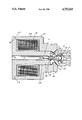
- the drawing is a longitudinal cross sectional view showing the electrohydraulic regulating valve.
- the electrohydraulic flow regulating valve embodying the invention comprises a housing 10 of a suitable soft magnetic material such as low carbon steel, an armature 11 also of soft magnetic low carbon steel and a dual headed valve 12 preferably non-magnetic.
- the housing includes an axial inlet member 13 at one end.
- An electrical coil 14 surrounds the armature 11 within housing 10 for generating magnetic flux.
- Outlet openings 15 in housing extend at an angle from adjacent the end of armature 11 to the exterior for supplying pressure fluid to the device being controlled by the regulating valve.
- An inlet opening 16 is provided in member 13 for the fluid or liquid the pressure of which is regulated.
- An axial exhaust opening or passageway 17 is provided in armature stem 24 and extends to a bevelled exhaust port seat 19 on stem 24.
- a bevelled frustoconical regulating seat area 20 is provided in housing 10.
- Valve 12 has spaced interconnected frustoconical heads 21, 22.
- Valve outlet head 21 of valve 12 controls the exhaust port seat 19 and valve inlet head 22 controls the regulating seat area 20.
- armature 11 is T-shaped in cross-section, having a head 23 of large diameter and a stem portion 24 of smaller cylindrical diameter portion 25 which projects into the housing 10.
- the small diameter portion 25 of armature 11 is in sliding engagement with the housing 10.
- a cavity 26 is provided in the housing at the inner end of the stem 11.
- Valve 12 controls the flow of fluid into the cavity 26 through a frustoconical sealing surface 22a on inlet heat 22 and inlet seat area 20 and flow out of the cavity through a sealing surface 21a on outlet head 21 and exhaust port seat 19 when the coil is de-energized.
- Valve 21 includes an integral axial extension 30 extending from head 21.
- a conical compression spring 31 is interposed between the valve inlet head 22 and the end of inlet member 13 and urges the dual head valve to hold the sealing surface of 21a of outlet head 21 against seat 19.
- Extension 30 and spring 31 function to improve the stability and positioning between the valve heads 21, 22 and seats 19, 20.
- a current of the desired amperage is applied to coil 14 creating a magnetic field through the armature and housing and across the air gap at 27, 28.
- This magnetic field across the air gap 27, 28 will create an inward or rightward force on the armature which is applied to valve 12 seated against exhaust seat 19.
- this force exceeds the force of the fluid from inlet opening 16 acting on the head 22 of the valve, the valve head 22 will lift off the regulating seat 20 forming a gap between sealing surface 22a and seat 20 allowing pressure fluid to flow into the cavity 26 and out through the apply ports 15 to the device being controlled by the regulating valve.
- the fluid pressure in cavity 26 acting on outlet ports 15 also acts on the end of the small diameter stem 24 of the armature 11 exerting an outward or leftward force.
- the fluid pressure acts against head 22 and the end of armature stem 24 in opposition to the force of the energized coil 14 urging armature 11 to the right.
- the imbalance in these forces causes armature movement in a direction to balance these forces at which point the output pressure will be constant.
Abstract
Description
Claims (6)
Priority Applications (1)
| Application Number | Priority Date | Filing Date | Title |
|---|---|---|---|
| US07/091,388 US4753263A (en) | 1987-08-31 | 1987-08-31 | Electrohydraulic regulating valves |
Applications Claiming Priority (1)
| Application Number | Priority Date | Filing Date | Title |
|---|---|---|---|
| US07/091,388 US4753263A (en) | 1987-08-31 | 1987-08-31 | Electrohydraulic regulating valves |
Publications (1)
| Publication Number | Publication Date |
|---|---|
| US4753263A true US4753263A (en) | 1988-06-28 |
Family
ID=22227521
Family Applications (1)
| Application Number | Title | Priority Date | Filing Date |
|---|---|---|---|
| US07/091,388 Expired - Lifetime US4753263A (en) | 1987-08-31 | 1987-08-31 | Electrohydraulic regulating valves |
Country Status (1)
| Country | Link |
|---|---|
| US (1) | US4753263A (en) |
Cited By (8)
| Publication number | Priority date | Publication date | Assignee | Title |
|---|---|---|---|---|
| EP0467128A2 (en) * | 1990-07-16 | 1992-01-22 | Spx Corporation | Electromagnetic solenoid valve with variable force motor |
| US5205324A (en) * | 1991-11-19 | 1993-04-27 | Pneumo Abex Corporation | Closed center valves |
| US5322260A (en) * | 1993-05-24 | 1994-06-21 | Borg-Warner Automotive, Inc. | Solenoid valve |
| US5326070A (en) * | 1993-05-24 | 1994-07-05 | Borg-Warner Automotive, Inc. | Solenoid valve |
| US5546064A (en) * | 1993-12-15 | 1996-08-13 | United Technologies Automotive, Inc. | Solenoid with plunger rod |
| US6102364A (en) * | 1997-07-30 | 2000-08-15 | Siemens Canada Limited | Control accuracy of a pulse-operated electromechanical device |
| US6276663B1 (en) | 2000-04-25 | 2001-08-21 | Acutex, Inc. | Normally rising variable force solenoid |
| US20110140016A1 (en) * | 2009-12-08 | 2011-06-16 | Robert Bosch Gmbh | Pressure-regulating valve for regulating the pressure in a high-pressure fuel accumulator of an internal combustion engine |
Citations (3)
| Publication number | Priority date | Publication date | Assignee | Title |
|---|---|---|---|---|
| US3906982A (en) * | 1972-08-28 | 1975-09-23 | Tescom Corp | Pressure regulator assembly |
| US4171004A (en) * | 1977-07-13 | 1979-10-16 | Vending Components, Inc. | Safety regulator for fluid pressure |
| US4598729A (en) * | 1981-06-19 | 1986-07-08 | Nippondenso Co., Ltd. | Negative pressure control valve |
-
1987
- 1987-08-31 US US07/091,388 patent/US4753263A/en not_active Expired - Lifetime
Patent Citations (3)
| Publication number | Priority date | Publication date | Assignee | Title |
|---|---|---|---|---|
| US3906982A (en) * | 1972-08-28 | 1975-09-23 | Tescom Corp | Pressure regulator assembly |
| US4171004A (en) * | 1977-07-13 | 1979-10-16 | Vending Components, Inc. | Safety regulator for fluid pressure |
| US4598729A (en) * | 1981-06-19 | 1986-07-08 | Nippondenso Co., Ltd. | Negative pressure control valve |
Cited By (10)
| Publication number | Priority date | Publication date | Assignee | Title |
|---|---|---|---|---|
| EP0467128A2 (en) * | 1990-07-16 | 1992-01-22 | Spx Corporation | Electromagnetic solenoid valve with variable force motor |
| EP0467128A3 (en) * | 1990-07-16 | 1992-02-26 | Spx Corporation | Electromagnetic solenoid valve with variable force motor |
| US5205324A (en) * | 1991-11-19 | 1993-04-27 | Pneumo Abex Corporation | Closed center valves |
| US5322260A (en) * | 1993-05-24 | 1994-06-21 | Borg-Warner Automotive, Inc. | Solenoid valve |
| US5326070A (en) * | 1993-05-24 | 1994-07-05 | Borg-Warner Automotive, Inc. | Solenoid valve |
| US5546064A (en) * | 1993-12-15 | 1996-08-13 | United Technologies Automotive, Inc. | Solenoid with plunger rod |
| US6102364A (en) * | 1997-07-30 | 2000-08-15 | Siemens Canada Limited | Control accuracy of a pulse-operated electromechanical device |
| US6276663B1 (en) | 2000-04-25 | 2001-08-21 | Acutex, Inc. | Normally rising variable force solenoid |
| US20110140016A1 (en) * | 2009-12-08 | 2011-06-16 | Robert Bosch Gmbh | Pressure-regulating valve for regulating the pressure in a high-pressure fuel accumulator of an internal combustion engine |
| US8667986B2 (en) * | 2009-12-08 | 2014-03-11 | Robert Bosch Gmbh | Pressure-regulating valve for regulating the pressure in a high-pressure fuel accumulator of an internal combustion engine |
Similar Documents
| Publication | Publication Date | Title |
|---|---|---|
| US5735503A (en) | Servo pressure regulator for a gas valve | |
| US5048790A (en) | Self-modulating control valve for high-pressure fluid flow | |
| US4848721A (en) | Hydraulic valve with integrated solenoid | |
| US5645263A (en) | Pilot valve for a flow amplyifying poppet valve | |
| US4494726A (en) | Control valve | |
| US20070210270A1 (en) | Pilot operated valve with a pressure balanced poppet | |
| JPH0652109B2 (en) | Pressure response pilot operated regulator valve | |
| US4565209A (en) | Pressure regulating valve with feedback control | |
| US4275758A (en) | Pressure control valve assembly | |
| US4114850A (en) | Modulating plug valve | |
| US4753263A (en) | Electrohydraulic regulating valves | |
| US3179123A (en) | Regulator and shut-off valve for rocket thrust control | |
| US4252296A (en) | Valve | |
| US4462566A (en) | Pressure compensated flow control system | |
| CN111271477A (en) | Electromagnetic stop safety valve | |
| US6474623B1 (en) | Valve mechanism and control | |
| JP2004069069A (en) | Solenoid operating pressure control valve | |
| JP2691741B2 (en) | Electromagnetically operable valve device | |
| GB2186349A (en) | Proportional solenoid valve | |
| US5058624A (en) | Flow control valve with stable modulation | |
| US4666125A (en) | Low leakage solenoid valve | |
| JPH0152763B2 (en) | ||
| JPH0447194B2 (en) | ||
| US2969806A (en) | Pressure regulator and shutoff valve | |
| ES8402052A1 (en) | Ventilator drive for a cooling plant, especially for rail vehicles. |
Legal Events
| Date | Code | Title | Description |
|---|---|---|---|
| AS | Assignment |
Owner name: SEALED POWER CORPORATION, 100 TERRACE PLAZA, MUSKE Free format text: ASSIGNMENT OF ASSIGNORS INTEREST.;ASSIGNOR:WARRICK, FRANK G.;REEL/FRAME:004781/0254 Effective date: 19870807 Owner name: SEALED POWER CORPORATION, A CORP. OF DE,MICHIGAN Free format text: ASSIGNMENT OF ASSIGNORS INTEREST;ASSIGNOR:WARRICK, FRANK G.;REEL/FRAME:004781/0254 Effective date: 19870807 |
|
| STCF | Information on status: patent grant |
Free format text: PATENTED CASE |
|
| FPAY | Fee payment |
Year of fee payment: 4 |
|
| FEPP | Fee payment procedure |
Free format text: PAYOR NUMBER ASSIGNED (ORIGINAL EVENT CODE: ASPN); ENTITY STATUS OF PATENT OWNER: LARGE ENTITY |
|
| FPAY | Fee payment |
Year of fee payment: 8 |
|
| FEPP | Fee payment procedure |
Free format text: PAYOR NUMBER ASSIGNED (ORIGINAL EVENT CODE: ASPN); ENTITY STATUS OF PATENT OWNER: LARGE ENTITY Free format text: PAYER NUMBER DE-ASSIGNED (ORIGINAL EVENT CODE: RMPN); ENTITY STATUS OF PATENT OWNER: LARGE ENTITY |
|
| AS | Assignment |
Owner name: SPX CORPORATION, MICHIGAN Free format text: CHANGE OF NAME;ASSIGNOR:SEALED POWER CORPORATION;REEL/FRAME:010133/0402 Effective date: 19990630 |
|
| AS | Assignment |
Owner name: ACUTEX, INC., OHIO Free format text: ASSIGNMENT OF ASSIGNORS INTEREST;ASSIGNOR:SPX CORPORATION;REEL/FRAME:010321/0951 Effective date: 19990730 |
|
| FPAY | Fee payment |
Year of fee payment: 12 |
|
| AS | Assignment |
Owner name: NATIONAL CITY BANK, AS COLLATERAL AGENT, OHIO Free format text: SECURITY INTEREST;ASSIGNOR:ACUTEX, INC.;REEL/FRAME:016470/0745 Effective date: 20050408 |
|
| AS | Assignment |
Owner name: BEAR STEARNS CORPORATE LENDING INC., AS COLLATERAL Free format text: FIRST LIEN INTELLECTUAL PROPERTY SECURITY AGREEMENT;ASSIGNOR:ACUTEX, INC.;REEL/FRAME:019781/0191 Effective date: 20070725 |
|
| AS | Assignment |
Owner name: BEAR STEARNS CORPORATE LENDING INC., AS COLLATERAL Free format text: SECOND LIEN INTELLECTUAL PROPERTY SECURITY AGREEMENT;ASSIGNOR:ACUTEX, INC.;REEL/FRAME:019795/0515 Effective date: 20070725 |
|
| AS | Assignment |
Owner name: ACUTEX, INC., OHIO Free format text: RELEASE OF SECURITY INTEREST AT REEL 016470 FRAME 0745;ASSIGNOR:NATIONAL CITY BANK;REEL/FRAME:019910/0920 Effective date: 20070918 |