US4747403A - Multi-frequency jet ventilation technique and apparatus - Google Patents
Multi-frequency jet ventilation technique and apparatus Download PDFInfo
- Publication number
- US4747403A US4747403A US06/822,535 US82253586A US4747403A US 4747403 A US4747403 A US 4747403A US 82253586 A US82253586 A US 82253586A US 4747403 A US4747403 A US 4747403A
- Authority
- US
- United States
- Prior art keywords
- gas
- valve
- chamber
- entrainment
- pulses
- Prior art date
- Legal status (The legal status is an assumption and is not a legal conclusion. Google has not performed a legal analysis and makes no representation as to the accuracy of the status listed.)
- Expired - Lifetime
Links
Images


Classifications
-
- A—HUMAN NECESSITIES
- A61—MEDICAL OR VETERINARY SCIENCE; HYGIENE
- A61M—DEVICES FOR INTRODUCING MEDIA INTO, OR ONTO, THE BODY; DEVICES FOR TRANSDUCING BODY MEDIA OR FOR TAKING MEDIA FROM THE BODY; DEVICES FOR PRODUCING OR ENDING SLEEP OR STUPOR
- A61M16/00—Devices for influencing the respiratory system of patients by gas treatment, e.g. mouth-to-mouth respiration; Tracheal tubes
- A61M16/0096—High frequency jet ventilation
-
- A—HUMAN NECESSITIES
- A61—MEDICAL OR VETERINARY SCIENCE; HYGIENE
- A61M—DEVICES FOR INTRODUCING MEDIA INTO, OR ONTO, THE BODY; DEVICES FOR TRANSDUCING BODY MEDIA OR FOR TAKING MEDIA FROM THE BODY; DEVICES FOR PRODUCING OR ENDING SLEEP OR STUPOR
- A61M16/00—Devices for influencing the respiratory system of patients by gas treatment, e.g. mouth-to-mouth respiration; Tracheal tubes
- A61M16/021—Devices for influencing the respiratory system of patients by gas treatment, e.g. mouth-to-mouth respiration; Tracheal tubes operated by electrical means
- A61M16/022—Control means therefor
- A61M16/024—Control means therefor including calculation means, e.g. using a processor
-
- A—HUMAN NECESSITIES
- A61—MEDICAL OR VETERINARY SCIENCE; HYGIENE
- A61M—DEVICES FOR INTRODUCING MEDIA INTO, OR ONTO, THE BODY; DEVICES FOR TRANSDUCING BODY MEDIA OR FOR TAKING MEDIA FROM THE BODY; DEVICES FOR PRODUCING OR ENDING SLEEP OR STUPOR
- A61M16/00—Devices for influencing the respiratory system of patients by gas treatment, e.g. mouth-to-mouth respiration; Tracheal tubes
- A61M16/04—Tracheal tubes
-
- A—HUMAN NECESSITIES
- A61—MEDICAL OR VETERINARY SCIENCE; HYGIENE
- A61M—DEVICES FOR INTRODUCING MEDIA INTO, OR ONTO, THE BODY; DEVICES FOR TRANSDUCING BODY MEDIA OR FOR TAKING MEDIA FROM THE BODY; DEVICES FOR PRODUCING OR ENDING SLEEP OR STUPOR
- A61M16/00—Devices for influencing the respiratory system of patients by gas treatment, e.g. mouth-to-mouth respiration; Tracheal tubes
- A61M16/10—Preparation of respiratory gases or vapours
- A61M16/12—Preparation of respiratory gases or vapours by mixing different gases
- A61M16/122—Preparation of respiratory gases or vapours by mixing different gases with dilution
- A61M16/125—Diluting primary gas with ambient air
- A61M16/127—Diluting primary gas with ambient air by Venturi effect, i.e. entrainment mixers
-
- A—HUMAN NECESSITIES
- A61—MEDICAL OR VETERINARY SCIENCE; HYGIENE
- A61M—DEVICES FOR INTRODUCING MEDIA INTO, OR ONTO, THE BODY; DEVICES FOR TRANSDUCING BODY MEDIA OR FOR TAKING MEDIA FROM THE BODY; DEVICES FOR PRODUCING OR ENDING SLEEP OR STUPOR
- A61M16/00—Devices for influencing the respiratory system of patients by gas treatment, e.g. mouth-to-mouth respiration; Tracheal tubes
- A61M16/10—Preparation of respiratory gases or vapours
- A61M16/14—Preparation of respiratory gases or vapours by mixing different fluids, one of them being in a liquid phase
- A61M16/16—Devices to humidify the respiration air
-
- A—HUMAN NECESSITIES
- A61—MEDICAL OR VETERINARY SCIENCE; HYGIENE
- A61M—DEVICES FOR INTRODUCING MEDIA INTO, OR ONTO, THE BODY; DEVICES FOR TRANSDUCING BODY MEDIA OR FOR TAKING MEDIA FROM THE BODY; DEVICES FOR PRODUCING OR ENDING SLEEP OR STUPOR
- A61M16/00—Devices for influencing the respiratory system of patients by gas treatment, e.g. mouth-to-mouth respiration; Tracheal tubes
- A61M16/0003—Accessories therefor, e.g. sensors, vibrators, negative pressure
- A61M2016/003—Accessories therefor, e.g. sensors, vibrators, negative pressure with a flowmeter
- A61M2016/0033—Accessories therefor, e.g. sensors, vibrators, negative pressure with a flowmeter electrical
Definitions
- This invention relates generally to ventilators for supplying gas to facilitate and support human respiration and particularly to ventilators which employ a high frequency jet of gas for respiratory therapy. More specifically, the present invention is directed to enhancing ventilation at supraphysiologic rates and especially to maximizing the tidal volume of gas delivered to a patient during respiration therapy while simultaneously minimizing patient discomfort and the possibility of causing or aggravating trauma. Accordingly, the general objects of the present invention are to provide novel and improved methods and apparatus of such character.
- the present invention is particularly well suited to high frequency jet ventilation.
- the use of high frequency jet ventilation has proven to be quite beneficial in the treatment of certain respiratory conditions.
- ventilation is achieved by enhancing the mass transfer processes in the lungs through high frequency oscillation of the supplied gas.
- pulsation frequency of the gas delivered by a jet ventilator increases, supplying the necessary tidal volume of inhalation gas becomes more difficult and is limited by the response time of mechanisms employed for generating the gas pulses.
- the requirements of reliability, ease of maintenance and susceptibility to sterilization are important design considerations for a ventilator. Portability is a further desirable characteristic.
- the principal objectives of the present invention are to provide a new and improved ventilation technique and a multi-frequency jet ventilator which operates in accordance with this technique and is compact, relatively easy to maintain, capable of being easily sterilized and supplies a maximized tidal volume of ventilation gas flow over a wide range of frequencies and duty cycles.
- apparatus in accordance with a preferred embodiment of the invention comprises a ventilator system which includes a novel entrainment module.
- the entrainment module forms an entrainment chamber having an axis, an inhalation gas supply outlet, an inlet port for a bias flow of low pressure gas and a discharge or vent port.
- the inlet and discharge ports are axially spaced from the supply outlet and are located at generally diametrically opposite positions of the entrainment chamber.
- the low pressure gas which will customarily be humidified, is continuously supplied to the inlet port from a first gas source to establish the bias flow during operation of the system.
- a nozzle extends into the entrainment chamber in a direction which is generally axially aligned with the inhalation gas supply outlet.
- the nozzle is in fluid communication with a source of relatively highly pressurized gas pulses and serves to inject a series of high velocity pressurized gas pulses into the entrainment chamber for traversal thereof in a generally axial direction toward the supply outlet.
- the gas pulses are injected from a zone generally located between the bias flow inlet and discharge ports, there being one high pressure pulse injected during the inspiratory phase of each cycle of the ventilator.
- a high velocity pulse from the nozzle entrains a relatively large amount of the low pressure gas from the bias flow in the entrainment chamber to produce an inhalation pulse which exits the chamber supply outlet.
- gases in the entrainment chamber including CO 2 exhaled by the patient which flows into the chamber via the supply outlet, are vented through the discharge port.
- the interior shape of the pulse injection nozzle is either convergent or convergent-divergent to increase the velocity of the gas comprising the pulses thus increasing the quantity of gas from the bias flow which is entrained.
- the entrainment module has a substantially T-shaped configuration, with the supply outlet being axially spaced from the nozzle opening and generally coaxial therewith, and contains no moving parts.
- a conduit couples the source of high pressure ventilation gas to the nozzle.
- a valve is interposed in this conduit to selectively interrupt the flow of pressurized gas to generate the high pressure gas pulses.
- the valve is actuated by a solenoid which drives the valve from a closed to a fully open position.
- An electronic control circuit provides signals which control the operation of the solenoid. These commmand signals, in a preferred embodiment, have a frequency, pulse width and duty cycle which may be selected to provide the optimum ventilation program for the patient to be treated.
- the command signals have a generally stepped waveform which includes an initial overdrive voltage of predetermined duration. The overdrive voltage functions to reduce the time interval for the solenoid to change the state of the valve whereby the time required for the valve to switch from the fully closed to fully open condition is minimized.
- the novel method of the present invention includes the steps of creating a humidified bias flow of gas and entraining gas from that bias flow to create a highly humidified inhalation gas.
- the entrainment consists of subjecting the bias flow to the effect of high velocity pulses of gas derived from a high pressure source of entrainment gas.
- the invention further contemplates the exercise of control over the entrainment gas to vary the frequency, duration and width of the gas pulses to satisfy the requirements of the treatment being performed.
- FIG. 1 is a functional block diagram of a multi-frequency jet ventilator in accordance with the present invention
- FIG. 2 is an enlarged fragmentary sectional view of a preferred embodiment of the entrainment module of the multi-frequency jet ventilator of FIG. 1;
- FIG. 3 is a functional block diagram of the control module of the multi-frequency jet ventilator of FIG. 1;
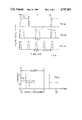
- FIGS. 4a, 4b and 4c are graphical illustrations of gas pulse trains provided to the entrainment module of FIG. 2 in response to the control signals generated by the control module of FIG. 3;
- FIG. 5 is a waveform diagram of a control voltage generated by the control module of FIG. 3.
- Ventilator 10 may be selectively employed at conventional ventilation frequencies or may be utilized as a high frequency jet ventilator. Ventilator 10 preferrably has a range of operational frequencies of from 4 breaths/minute (1/15 Hz.) to 3000 breaths/minute (50 Hz) and an inspiratory time, i.e., a duty cycle, in the range of 5% to 95% as will be more fully described below.
- the ventilator 10 will supply respiratory gas to a patient via either a cuffed or uncuffed endotracheal tube (not illustrated) and is adaptable for ventilating with air, air/oxygen, helium/oxygen or any other suitable gas or combination of gases.
- Ventilator 10 has a compact, lightweight construction and may be either battery or line current powered.
- Ventilator 10 is an integrated modular system which generally comprises a control unit 12, a high pressure gas supply unit 14, a low pressure gas supply unit 15 and an entrainment module 16.
- the control unit 12 comprises the electronic controls, safety system and the electrical power supply for the ventilator.
- the high pressure gas supply unit 14 comprises a source of high pressure gas, a gas pressure regulation system and a valve subassembly for producing controlled pulses of the gas derived from the high pressure source.
- the low pressure gas supply unit 15 comprises a source of low pressure gas and a humidification system for the gas.
- the entrainment module 16 produces, from the pulses of high pressure gas and the humidified low pressure gas, the required output of the ventilator.
- the gas flow lines are designated by heavy lines and the electrical interconnections are designated by thin lines in the drawing.
- the control unit 12 is connected to the supply unit 14 via conventional separable electrical connectors.
- the gas supply units 14 and 15 and entrainment module 16 are interconnected by standard flexible hoses.
- the above-mentioned modular units and their sub-units may be easily connected and disconnected.
- the modular construction thus facilitates maintenance of the ventilator and also provides a ventilator which, to the extent required, may be easily disinfected and sterilized as will be more fully apparent from the discussion below.
- control unit 12 comprises an electronic control module 20 which generates control pulses for operating a solenoid actuated valve 22 in supply unit 14.
- the control module 20 also provides input signals to an electronic safety module 24.
- the safety module 24 in the manner to be described below, controls an electrically operated shutoff valve 26 in the primary, i.e., high pressure, gas supply line and is also connected to an alarm system 28.
- the pressurized gas which appears at the output port of accumulator 34 has a regulated substantially constant pressure in the range of between 5 psi and 250 psi.
- the pressurized gas flows from the accumulator 34 via a flow sensor 36 and valve 22 to entrainment module 16.
- the flow sensor 36 provides an information bearing input signal to safety module 24 whereby the nature of the gas flow to the entrainment module 16 derived from high pressure source 30 may be continuously monitored to provide a means for actuating the alarm 28 in the event that the aforementioned gas flow is not within the selected and required operational limits of the ventilator.
- the alarm 28 is preferably both an audible and a visual alarm.
- the safety module 24, which is preferrably a microprocessor, is programmed to monitor the operation of the ventilator, especially the primary gas flow to the entrainment module and the pressure downstream of the entrainment module, in order to determine whether the operating parameters are within pre-established ranges. Should a monitored parameter move into a range which is unsafe to the patient, module 24 will command the closing of shutoff valve 26.
- a secondary pressurized gas source 42 within unit 15, is coupled via a shutoff valve 44 to a humidifier 46.
- the output of humidifier 46 is a bias flow of heated humidified gas which is continuously supplied to the entrainment module 40 at a relatively low pressure such as 5 psi.
- the secondary gas source 42 is typically in the form of one or more tanks containing the same gas as supplied by "high" pressure source 30.
- Humidifier 46 is preferably a cascade bubble humidifier and causes the bias flow to have approximately 100% relative humidity.
- an ultrasonic nebulizer 47 may be employed to introduce a vapor mist to the bias flow of humidified gas.
- the output stream is supplied to the patient via an endotracheal tube (not fully illustrated).
- the entrainment module 16 also functions to receive gases exhaled by the patient. Depending on the state of a two-way flow control valve 48, the exhaled gas is either vented to the ambient atmosphere or delivered to a reclaimation unit 49. Accordingly, during operation the vent port of the entrainment module will be maintained at a constant pressure which is equal to or less than atmospheric.
- a pressure sensor 50 may be interposed in the gas path which extends from the entrainment module to the endotracheal tube for sensing the pressure immediately upstream of the endotracheal tube and providing a corresponding input signal to the safety module 24 for insuring safe operation of the ventilator.
- the entrainment module 16 comprises a housing 51 which interiorly forms an entrainment chamber 52.
- Housing 51 is a generally T-shaped cylindrical member which has an open output end.
- a fitting 54 at the output end fluidically couples chamber 52 to a conduit 56 which leads to or comprises the end of the endotracheal tube.
- Gas pulses, produced by modulating the gas exiting accumulator 34 by means of valve 22, are injected into the entrainment chamber 52 through a nozzle 58.
- Nozzle 58 is a convergent or convergent-divergent nozzle and thus the velocity of the gas downstream of the nozzle throat is high.
- Nozzle 58 extends axially into chamber 52 through an end wall of the housing 51 along the central axis of the chamber.
- Nozzle 58 is aerodynamically shaped to enhance entrainment efficiency by directing the low pressure bias flow in the downstream direction in chamber 52.
- Nozzle 58 thus preferrably has a forwardly tapering convergent external profile as shown, i.e., nozzle 58 is externally shaped to smoothly diverge in the upstream direction from the discharge end thereof.
- An inlet leg 62 and an outlet leg 64 protrude radially at diametrically opposite locations of housing 51. Legs 62 and 64 are substantially identical and are equidistant from the centrally disposed nozzle 58.
- Inlet leg 62 functions as a connector structure for coupling to a conduit for supplying the low velocity bias stream of humidified gas to the entrainment chamber 52 via port 66 as illustrated by the arrows in FIG. 2.
- the humidified gas is continuously supplied to the entrainment chamber.
- humidified gas is entrained by a high velocity gas pulse injected into chamber 52 via the nozzle 58 and propelled axially through the chamber to conduit 56 and thence to the patient via the endotracheal tube.
- the ventilating gas pulses delivered to the patient will be comprised primarily of humidified gas supplied via inlet leg 62, the humidified gas being entrained by the pulses of dry gas supplied via nozzle 58. Accordingly, the patient will receive gas having the highest possible relative humidity.
- the gas exhaled by the patient returns via conduit 56 to the entrainment chamber 52.
- the exhaled gas is entrained by the low velocity bias flow and is thus discharged through discharge or vent port 68 which leads to outlet leg 64.
- Leg 64 is coupled to a conduit for conducting the exhaled gas and excess humidified gas to valve 48.
- the expired carbon dioxide from the patient is discharged through port 68 in part due to the driving force of the bias flow of humidified gas which prevents the exhaled gases from entering port 66 and thus a vent or discharge control valve is not required.
- the entrainment of the humidified gas by the high velocity pulses or slugs of primary gas is facilitated by the convergent exterior shape of nozzle 58 which, as mentioned above, functions as a flow control surface.
- the entrainment of the humidified gas is improved by the placement of the outlet 60 of nozzle 58 at an axial location of the chamber which is proximate the downstream axial terminus of the inlet port 66. Consequently, the high velocity pulse is injected into the chamber at a location slightly downstream from the entry of the humidified gas.
- the continuous supply of the low pressure humidified secondary gas functions to alternately supply humidified gas for entrainment and to remove the expired carbon dioxide from the ventilator unit without the use of any mechanical valves which would otherwise tend to deteriorate the entrainment effects and, thus, would result in lower tidal volumes.
- a low compliant tube connects nozzle 58 to the solenoid actuated control valve 22.
- Valve 22 is a bi-state valve having an open and closed position.
- the command signals generated by control module 20 and applied to the solenoid of valve 22 determine the frequency and duration of the gas pulses delivered to nozzle 58.
- valve 22 is cyclically opened and closed for selected time intervals to interrupt the flow of pressurized gas to nozzle 58 to thereby produce the desired gas pulse train characteristics to provide optimum treatment for the patient.
- the characteristics of the train of pressurized gas pulses produced by valve 22 may best be appreciated by reference to FIGS. 4a, 4b and 4c.
- the horizontal axes represent the time in milliseconds and the vertical axes represent the flow rate of the high velocity ventilation gas exiting nozzle 58.
- the letter T represents the time of one ventilation cycle, i.e., the time of a inspiratory phase plus the time of a following expiratory phase.
- the symbol t 1 represents the time interval during which valve 22 is open.
- the time interval in which valve 22 is opened i.e., the inspiratory time
- the graph of FIG. 4a represents the pulse train characteristics when valve 22 is opened and closed at a 5 Hz. frequency.
- Graph 4b represents the pulse characteristics when valve 22 is opened and closed at a 10 Hz. frequency.
- FIG. 4c represents the pulse characteristics when valve 22 is opened and closed at a 20 Hz. frequency.
- the volume of gas supplied by the valve per breath is equal to the area under the flow rate-time curve of the graphs of FIG. 4.
- the solid lines represent the flow characteristics for ventilator 10.
- the broken lines represent the flow characteristics for a ventilator which does not incorporate a feature for reducing the time required for the valve to change states in accordance with the present invention. It will be appreciated that the depicted curves have a trapezoidal shape rather than a square wave shape due to the incremental time interval required for valve 22 to change from one state to another, i.e., from a fully closed state to a fully open state and vice versa. In the prior art, at high pulse frequencies there was insufficient time for the valve to open completely before receipt of a "close" command.
- a flow pattern as represented by the broken line showing of FIG. 4c leads to a drastic reduction in the tidal volume, i.e., the volume of gas supplied to the patient, during the inspiratory phase. Consequently, in order that sufficient tidal volumes be supplied at high ventilation frequencies, the valve must be caused to react quickly to "open" commands and should remain open for a significant portion of the inspiratory phase.
- valve 22 is opened and closed by means of solenoid 70 which is responsive to command signals generated by the control module 20.
- Control module 20 includes a square wave generator 72.
- a resistance capacitance network 73 is adjustable in the conventional manner to vary the time constant of and thus the output frequency of square wave generator 72.
- the square wave output signal of generator 72 is applied to a timer circuit 74.
- an adjustable voltage magnitude selection circuit and an adjustable duty cycle selection circuit are coupled to timer 74 to cause the timer to provide an output waveform having a selected amplitude (voltage V 1 ), pulse width (time t 1 ) and frequency f.
- Voltage V 1 is selected to be the minimum solenoid holding voltage required to sustain valve 22 in the opened position.
- This voltage is typically lower than the voltage necessary to cause the solenoid to open the valve.
- Use of a low voltage to maintain the valve open reduces the closing time for the valve.
- the closing time is further reduced by a short duration large negative voltage spike -V 2 which is generated at the end of the inspiratory phase of the cycle upon removal of the timer 74 output voltage from the valve solenoid.
- Time t 1 is selected to provide the optimum inspiratory time per ventilation cycle.
- Frequency f is selected to provide the optimum ventilation frequency in accordance with the condition of the patient.
- the square wave from circuit 72 is also applied to an overdrive timer circuit 76.
- the overdrive timer circuit is also adjustable to generate a second waveform having a second amplitude (voltage V 3 -V 1 ) and second pulse width (time t 2 ) with the same frequency f as and in phase with the waveform provided by timer 74.
- Voltage V 3 -V 1 and time t 2 are selected to reduce the valve opening time as detailed hereinafter.
- the two waveforms are combined, as represented schematically by summing circuit 77, and applied to solenoid 70.
- the waveform applied to solenoid 70 is illustrated in FIG. 5.
- the period of one opening and closing phase or cycle of valve 22, and hence the ventilation cycle, is given by time T.
- the overdrive voltage V 3 -V 1 By applying the overdrive voltage V 3 -V 1 to the solenoid, the overdrive voltage having an amplitude which is at least three times as great as the holding voltage V 1 , a greater electromagnetic force is generated, and the opening time of the valve is significantly reduced.
- the tidal volumes produced by the ventilator at high frequencies is not substantially reduced by the time required for the valve to change its state.
- the broken lines illustrate generally the pulse characteristics without application of the overdrive voltage to the solenoid and the solid lines represent the pulse characteristics of the ventilator when the foregoing described overdrive voltage is applied from the control module.
- the ventilator 10 is operated by selecting an optimum frequency and duty cycle, i.e., the ratio of inspiration time to ventilation cycle time, for the condition of the patient.
- the tidal volume of ventilation gas supplied to the patient is a function of pulse frequency and duration as well as gas pressure.
- Pressure regulator 32 regulates the pressure by conventional means.
- the control module functions to electronically control valve 22 to provide the optimum ventilation characteristics. The latter characteristics may change over the treatment period and the ventilator of the present invention is capable of manual or automatic readjustment in accordance with varying patient requirements.
- the control and safety modules may be a single subassembly including a programmable microprocessor and the operational mode may be entered from a keyboard and/or selected from preprogrammed data.
- the ventilator Since variation of the ventilation parameters can be accomplished without disconnecting the patient from the ventilator, trauma is avoided that could otherwise occur. It should be appreciated that since the ventilator is of modular construction, sterilization and maintenance of the unit can be relatively easily achieved.
- the entrainment module 16 has no moving components and thus may be easily disconnected from the ventilator for sterilization and/or replacement.
- the present invention has the flexibility, particularly operational parameters which are adjustable over broad ranges, which enables its use in a synchronous intermittent mandatory ventilation (IMV) mode.
- IMV mode will be selected, via the microprocessor based control module 20, when it is desired to attempt to wean a patient from the ventilator.
- a pulse at a frequency less than the normal breathing rate, will be provided by a clock in the microprocessor to trigger the generation of command signals for the valve 22 solenoid.
- a sensor 80 which could be a pressure sensor in the endotracheal tube, will sense spontaneous breathing by the patient and provide signals commensurate therewith which are inputted to control module 20.
- the valve 22 will open at the selected frequency except each time spontaneous exhalation is sensed, in which case the opening of the valve will be delayed until the end of exhalation and the clock will be reset to zero.
- the present invention may also, with the removal of the entrainment module 16 and low pressure gas supply unit 15, be employed in the case of a transcutaneous cricothyroidalostomy.
- a patient experiencing breathing difficulty cannot be provided with an endotracheal tube. That is, the proper insertion of an endotracheal tube may require as long as one-half hour, requires good lighting and requires a highly trained medical professional.
- the present invention with the entrainment module removed but a nozzle similar to nozzle 58 retained, can be utilized by medical technicians in the following manner. A needle with associated catheter will be inserted into the trachea, the needle will then be withdrawn and the nozzle then inserted into the trachea via the catheter. Jet ventilation may then be started with exhalation being via the patient's mouth and/or nose.
Abstract
Description
Claims (21)
Priority Applications (8)
| Application Number | Priority Date | Filing Date | Title |
|---|---|---|---|
| US06/822,535 US4747403A (en) | 1986-01-27 | 1986-01-27 | Multi-frequency jet ventilation technique and apparatus |
| JP62015906A JPS62183763A (en) | 1986-01-27 | 1987-01-26 | Variable frequency jet ventilation apparatus |
| DE8787300665T DE3783621T2 (en) | 1986-01-27 | 1987-01-27 | JET VENTILATION SYSTEM WITH VARIABLE FREQUENCY. |
| CA000528258A CA1287544C (en) | 1986-01-27 | 1987-01-27 | High frequency jet ventilation technique and apparatus |
| EP87300665A EP0234736B1 (en) | 1986-01-27 | 1987-01-27 | Variable frequency jet ventilation system |
| IL81478A IL81478A0 (en) | 1986-01-27 | 1987-02-04 | Multi-frequency jet ventilation method and apparatus |
| US07/167,586 US4838259A (en) | 1986-01-27 | 1988-03-14 | Multi-frequency jet ventilation technique and apparatus |
| CA000616072A CA1313245C (en) | 1986-01-27 | 1991-05-13 | High frequency jet ventilation technique and apparatus |
Applications Claiming Priority (1)
| Application Number | Priority Date | Filing Date | Title |
|---|---|---|---|
| US06/822,535 US4747403A (en) | 1986-01-27 | 1986-01-27 | Multi-frequency jet ventilation technique and apparatus |
Related Child Applications (1)
| Application Number | Title | Priority Date | Filing Date |
|---|---|---|---|
| US07/167,586 Division US4838259A (en) | 1986-01-27 | 1988-03-14 | Multi-frequency jet ventilation technique and apparatus |
Publications (1)
| Publication Number | Publication Date |
|---|---|
| US4747403A true US4747403A (en) | 1988-05-31 |
Family
ID=25236308
Family Applications (1)
| Application Number | Title | Priority Date | Filing Date |
|---|---|---|---|
| US06/822,535 Expired - Lifetime US4747403A (en) | 1986-01-27 | 1986-01-27 | Multi-frequency jet ventilation technique and apparatus |
Country Status (6)
| Country | Link |
|---|---|
| US (1) | US4747403A (en) |
| EP (1) | EP0234736B1 (en) |
| JP (1) | JPS62183763A (en) |
| CA (1) | CA1287544C (en) |
| DE (1) | DE3783621T2 (en) |
| IL (1) | IL81478A0 (en) |
Cited By (96)
| Publication number | Priority date | Publication date | Assignee | Title |
|---|---|---|---|---|
| US4838259A (en) * | 1986-01-27 | 1989-06-13 | Advanced Pulmonary Technologies, Inc. | Multi-frequency jet ventilation technique and apparatus |
| US4874362A (en) * | 1986-03-27 | 1989-10-17 | Wiest Peter P | Method and device for insufflating gas |
| US5080093A (en) * | 1987-07-08 | 1992-01-14 | Vortran Medical Technology, Inc. | Intermittant signal actuated nebulizer |
| US5280784A (en) * | 1990-09-19 | 1994-01-25 | Paul Ritzau Pari-Werk Gmbh | Device in particular and inhalating device for treating the lung and the respiratory tracts |
| US5303699A (en) * | 1991-11-18 | 1994-04-19 | Intermed Equipamento Medico Hospitalar Ltda. | Infant ventilator with exhalation valves |
| US5322057A (en) * | 1987-07-08 | 1994-06-21 | Vortran Medical Technology, Inc. | Intermittent signal actuated nebulizer synchronized to operate in the exhalation phase, and its method of use |
| US5546930A (en) * | 1992-09-28 | 1996-08-20 | Engstrom Medical Aktiebolag | Patient connector with HME, filter, and nebulizer connection |
| US5555880A (en) * | 1994-01-31 | 1996-09-17 | Southwest Research Institute | High frequency oscillatory ventilator and respiratory measurement system |
| US5611335A (en) * | 1995-06-06 | 1997-03-18 | Makhoul; Imad R. | High-frequency fan ventilator |
| US6029666A (en) * | 1995-05-02 | 2000-02-29 | Alexander Aloy | Device for delivering a ventilation gas |
| US6091973A (en) * | 1995-04-11 | 2000-07-18 | Resmed Limited | Monitoring the occurrence of apneic and hypopneic arousals |
| US6123082A (en) * | 1996-12-18 | 2000-09-26 | Resmed Limited | Device for preventing or reducing the passage of air through the mouth |
| US6138675A (en) * | 1993-11-05 | 2000-10-31 | Resmed Ltd. | Determination of the occurrence of an apnea |
| US6155986A (en) * | 1995-06-08 | 2000-12-05 | Resmed Limited | Monitoring of oro-nasal respiration |
| US6182657B1 (en) | 1995-09-18 | 2001-02-06 | Resmed Limited | Pressure control in CPAP treatment or assisted respiration |
| US6213119B1 (en) * | 1995-10-23 | 2001-04-10 | Resmed Limited | Inspiratory duration in CPAP or assisted respiration treatment |
| US6216691B1 (en) | 1997-11-03 | 2001-04-17 | Resmed Limited | Mounting body |
| US6237592B1 (en) | 1995-07-03 | 2001-05-29 | Resmed Limited | Auto-calibration of pressure transducer offset |
| WO2001037911A1 (en) * | 1999-11-23 | 2001-05-31 | A+ Science Invest Ab | Anaesthesia unit |
| US6240921B1 (en) | 1993-12-01 | 2001-06-05 | Resmed, Ltd. | Automated stop/start control in the administration of CPAP treatment |
| US6279569B1 (en) | 1996-08-14 | 2001-08-28 | Resmed Limited | Determination of leak and respiratory airflow |
| US6332463B1 (en) | 1995-09-15 | 2001-12-25 | Resmed Limited | Flow estimation and compensation of flow-induced pressure swings in CPAP treatment and assisted respiration |
| US6336454B1 (en) | 1997-05-16 | 2002-01-08 | Resmed Limited | Nasal ventilation as a treatment for stroke |
| US6398739B1 (en) | 1987-06-26 | 2002-06-04 | Resmed Limited | Device and method for nonclinical monitoring of breathing during sleep, control of CPAP treatment and preventing apnea |
| US6397841B1 (en) | 1997-06-18 | 2002-06-04 | Resmed Limited | Apparatus for supplying breathable gas |
| US20020072700A1 (en) * | 2000-06-30 | 2002-06-13 | Mantell Robert R. | Method and apparatus for humidification and warming of air |
| US20020124848A1 (en) * | 1987-06-26 | 2002-09-12 | Sullivan Colin Edward | Method and apparatus useful in the diagnosis of obstructive sleep apnea of a patient |
| US6457472B1 (en) | 1996-12-12 | 2002-10-01 | The Johns Hopkins University | Method and apparatus for providing ventilatory support to a patient |
| US6532957B2 (en) | 1996-09-23 | 2003-03-18 | Resmed Limited | Assisted ventilation to match patient respiratory need |
| US6557554B1 (en) * | 1999-10-29 | 2003-05-06 | Suzuki Motor Corporation | High-frequency oscillation artificial respiration apparatus |
| US6581597B2 (en) * | 2000-01-11 | 2003-06-24 | Suzuki Motor Corporation | High-frequency oscillation artificial respiration apparatus |
| US20050005936A1 (en) * | 2003-06-18 | 2005-01-13 | Wondka Anthony David | Methods, systems and devices for improving ventilation in a lung area |
| US20050056283A1 (en) * | 2003-09-17 | 2005-03-17 | Levi Andrew P. | Method and system for integrating ventilator and medical device activities |
| US20050133033A1 (en) * | 2003-12-20 | 2005-06-23 | Drager Medical Ag & Co. | Device and process for metering breathing gas |
| US20050192538A1 (en) * | 2004-02-26 | 2005-09-01 | Voege James A. | Method and apparatus for regulating fluid flow or conserving fluid flow |
| US7000610B2 (en) * | 1999-12-17 | 2006-02-21 | Maquet Critcal Care Ab | High frequency oscillator ventilator |
| US20060144396A1 (en) * | 2003-08-04 | 2006-07-06 | Devries Douglas F | Portable ventilator system |
| US20060249153A1 (en) * | 2003-08-04 | 2006-11-09 | Pulmonetic Systems, Inc. | Mechanical ventilation system utilizing bias valve |
| US20070000490A1 (en) * | 2003-08-04 | 2007-01-04 | Devries Douglas F | Portable ventilator system |
| US20070119454A1 (en) * | 1991-12-20 | 2007-05-31 | Resmed Limited | Patient interface assembly for CPAP respiratory apparatus |
| US20070163579A1 (en) * | 2006-01-13 | 2007-07-19 | Shenzhen Mindray Bio-Medical Electronics Co., Ltd. | Method and an apparatus for monitoring and controlling flows |
| US20080029088A1 (en) * | 2006-05-18 | 2008-02-07 | Breathe Technologies, Inc. | Tracheostoma spacer, tracheotomy method, and device for inserting a tracheostoma spacer |
| US20080041371A1 (en) * | 2003-08-11 | 2008-02-21 | Lutz Freitag | Method And Arrangement For Respiratory Support For A Patient Airway Prosthesis And Catheter |
| US20080092892A1 (en) * | 2003-08-04 | 2008-04-24 | Pulmonetic Systems, Inc. | Compressor Control System for a Portable Ventilator |
| WO2008019102A3 (en) * | 2006-08-03 | 2008-07-03 | Breathe Technologies Inc | Methods and devices for minimally invasive respiratory support |
| US7448594B2 (en) | 2004-10-21 | 2008-11-11 | Ameriflo, Inc. | Fluid regulator |
| US20090107494A1 (en) * | 2005-09-20 | 2009-04-30 | Lutz Freitag | Systems, methods and apparatus for respiratory support of a patient |
| US20090156953A1 (en) * | 2007-05-18 | 2009-06-18 | Breathe Technologies, Inc. | Methods and devices for sensing respiration and providing ventilation therapy |
| US7617826B1 (en) | 2004-02-26 | 2009-11-17 | Ameriflo, Inc. | Conserver |
| WO2010022363A1 (en) * | 2008-08-22 | 2010-02-25 | Breathe Technologies, Inc. | Methods and devices for providing mechanical ventilation with an open airway interface |
| US20110126836A1 (en) * | 2009-12-01 | 2011-06-02 | Nellcor Puritan Bennett Llc | Exhalation Valve Assembly With Selectable Contagious/Non-Contagious Latch |
| US8136527B2 (en) | 2003-08-18 | 2012-03-20 | Breathe Technologies, Inc. | Method and device for non-invasive ventilation with nasal interface |
| US8211052B1 (en) | 2006-07-13 | 2012-07-03 | Lexion Medical Llc | Charged hydrator |
| US8360060B2 (en) | 1993-11-05 | 2013-01-29 | Resmed Limited | Distinguishing between closed and open airway apneas and treating patients accordingly |
| US8434479B2 (en) | 2009-02-27 | 2013-05-07 | Covidien Lp | Flow rate compensation for transient thermal response of hot-wire anemometers |
| US8439036B2 (en) | 2009-12-01 | 2013-05-14 | Covidien Lp | Exhalation valve assembly with integral flow sensor |
| US8439037B2 (en) | 2009-12-01 | 2013-05-14 | Covidien Lp | Exhalation valve assembly with integrated filter and flow sensor |
| US8469031B2 (en) | 2009-12-01 | 2013-06-25 | Covidien Lp | Exhalation valve assembly with integrated filter |
| USD692556S1 (en) | 2013-03-08 | 2013-10-29 | Covidien Lp | Expiratory filter body of an exhalation module |
| US8567399B2 (en) | 2007-09-26 | 2013-10-29 | Breathe Technologies, Inc. | Methods and devices for providing inspiratory and expiratory flow relief during ventilation therapy |
| USD693001S1 (en) | 2013-03-08 | 2013-11-05 | Covidien Lp | Neonate expiratory filter assembly of an exhalation module |
| USD701601S1 (en) | 2013-03-08 | 2014-03-25 | Covidien Lp | Condensate vial of an exhalation module |
| US8770193B2 (en) | 2008-04-18 | 2014-07-08 | Breathe Technologies, Inc. | Methods and devices for sensing respiration and controlling ventilator functions |
| US8776793B2 (en) | 2008-04-18 | 2014-07-15 | Breathe Technologies, Inc. | Methods and devices for sensing respiration and controlling ventilator functions |
| US8800557B2 (en) | 2003-07-29 | 2014-08-12 | Covidien Lp | System and process for supplying respiratory gas under pressure or volumetrically |
| US8844537B1 (en) | 2010-10-13 | 2014-09-30 | Michael T. Abramson | System and method for alleviating sleep apnea |
| US8925545B2 (en) | 2004-02-04 | 2015-01-06 | Breathe Technologies, Inc. | Methods and devices for treating sleep apnea |
| US8939152B2 (en) | 2010-09-30 | 2015-01-27 | Breathe Technologies, Inc. | Methods, systems and devices for humidifying a respiratory tract |
| US20150059743A1 (en) * | 2012-03-09 | 2015-03-05 | Air Water Inc. | Ventilator |
| USD731048S1 (en) | 2013-03-08 | 2015-06-02 | Covidien Lp | EVQ diaphragm of an exhalation module |
| USD731065S1 (en) | 2013-03-08 | 2015-06-02 | Covidien Lp | EVQ pressure sensor filter of an exhalation module |
| USD731049S1 (en) | 2013-03-05 | 2015-06-02 | Covidien Lp | EVQ housing of an exhalation module |
| USD736905S1 (en) | 2013-03-08 | 2015-08-18 | Covidien Lp | Exhalation module EVQ housing |
| US9132250B2 (en) | 2009-09-03 | 2015-09-15 | Breathe Technologies, Inc. | Methods, systems and devices for non-invasive ventilation including a non-sealing ventilation interface with an entrainment port and/or pressure feature |
| US9180270B2 (en) | 2009-04-02 | 2015-11-10 | Breathe Technologies, Inc. | Methods, systems and devices for non-invasive open ventilation with gas delivery nozzles within an outer tube |
| USD744095S1 (en) | 2013-03-08 | 2015-11-24 | Covidien Lp | Exhalation module EVQ internal flow sensor |
| US20160151599A1 (en) * | 2010-11-23 | 2016-06-02 | Carefusion 2200, Inc. | Humidification system |
| USD775345S1 (en) | 2015-04-10 | 2016-12-27 | Covidien Lp | Ventilator console |
| US20170021125A1 (en) * | 2014-04-11 | 2017-01-26 | Stamford Devices Limited | High flow nasal therapy system |
| US9629971B2 (en) | 2011-04-29 | 2017-04-25 | Covidien Lp | Methods and systems for exhalation control and trajectory optimization |
| US9649458B2 (en) | 2008-09-30 | 2017-05-16 | Covidien Lp | Breathing assistance system with multiple pressure sensors |
| US20170348502A1 (en) * | 2011-11-07 | 2017-12-07 | Mallinckrodt Hospital Products IP Limited | Apparatus and method for monitoring nitric oxide delivery |
| US9950135B2 (en) | 2013-03-15 | 2018-04-24 | Covidien Lp | Maintaining an exhalation valve sensor assembly |
| US9962512B2 (en) | 2009-04-02 | 2018-05-08 | Breathe Technologies, Inc. | Methods, systems and devices for non-invasive ventilation including a non-sealing ventilation interface with a free space nozzle feature |
| US20180160939A1 (en) * | 2016-12-09 | 2018-06-14 | Physio-Control, Inc. | Capnograph system further detecting spontaneous patient breaths |
| US10058664B2 (en) | 2009-12-15 | 2018-08-28 | Koninklijke Philips N.V. | System and method for supporting sub-physiologic and physiologic tidal volumes in spontaneous or non-spontaneous breathing during high frequency ventilation |
| US10099028B2 (en) | 2010-08-16 | 2018-10-16 | Breathe Technologies, Inc. | Methods, systems and devices using LOX to provide ventilatory support |
| US10252020B2 (en) | 2008-10-01 | 2019-04-09 | Breathe Technologies, Inc. | Ventilator with biofeedback monitoring and control for improving patient activity and health |
| US10369389B2 (en) | 2008-06-23 | 2019-08-06 | Be Intellectual Property, Inc. | System for regulating the dispensing of commercial aircraft passenger oxygen supply |
| US10675423B2 (en) | 2015-05-19 | 2020-06-09 | David Kaczka | Systems and methods for multi-frequency oscillatory ventilation |
| US10792449B2 (en) | 2017-10-03 | 2020-10-06 | Breathe Technologies, Inc. | Patient interface with integrated jet pump |
| US20200398009A1 (en) * | 2014-08-14 | 2020-12-24 | Jagdish Chaturvedi | Systems for automatically removing fluid from multiple regions of a respiratory tract |
| US11154672B2 (en) | 2009-09-03 | 2021-10-26 | Breathe Technologies, Inc. | Methods, systems and devices for non-invasive ventilation including a non-sealing ventilation interface with an entrainment port and/or pressure feature |
| US11497869B2 (en) | 2011-12-07 | 2022-11-15 | Covidien Lp | Methods and systems for adaptive base flow |
| US11833297B2 (en) | 2011-12-31 | 2023-12-05 | Covidien Lp | Methods and systems for adaptive base flow and leak compensation |
| US11896767B2 (en) | 2020-03-20 | 2024-02-13 | Covidien Lp | Model-driven system integration in medical ventilators |
Families Citing this family (9)
| Publication number | Priority date | Publication date | Assignee | Title |
|---|---|---|---|---|
| GB8913084D0 (en) * | 1989-06-07 | 1989-07-26 | Whitwam James G | A medical ventilator |
| GB8913085D0 (en) * | 1989-06-07 | 1989-07-26 | Whitwam James G | Improvements in or relating to medical ventilators |
| US5239994A (en) * | 1991-05-10 | 1993-08-31 | Bunnell Incorporated | Jet ventilator system |
| ES2121691B1 (en) * | 1996-08-13 | 1999-08-01 | Sotos Lucas Picazo | MECHANICAL VENTILATION SYSTEM BY CONTINUOUS EXTRATRACHAEAL JET. |
| DE102004063158A1 (en) * | 2004-12-29 | 2006-07-13 | Weinmann Geräte für Medizin GmbH + Co. KG | Apparatus for ventilation and method for controlling a ventilator |
| US8402970B2 (en) | 2008-03-14 | 2013-03-26 | General Electric Company | System and method for integrated high frequency oscillatory ventilation |
| US20160235939A1 (en) | 2013-09-05 | 2016-08-18 | Eupnea Technologies, Inc | Apparatus and method to provide breathing support |
| US9345850B2 (en) | 2013-09-05 | 2016-05-24 | Eupnea Technologies, Inc. | Apparatus and method to provide breathing support |
| ES2926416B2 (en) * | 2021-04-16 | 2023-11-15 | Sotos Lucas Picazo | RESPIRATOR FOR MECHANICAL VENTILATION, FLOW CONTROL AND CONDITIONING EQUIPMENT ASSOCIATED THEREWITH, AND METHOD OF OPERATION OF A RESPIRATOR FOR MECHANICAL VENTILATION |
Citations (31)
| Publication number | Priority date | Publication date | Assignee | Title |
|---|---|---|---|---|
| FR62653E (en) * | 1951-04-16 | 1955-06-16 | Improvements to devices such as oxygen inhalers, especially for breathing at high altitude | |
| US2830583A (en) * | 1956-01-27 | 1958-04-15 | Charles W Bailey | Electrically controlled breathing apparatus |
| US3633576A (en) * | 1969-10-24 | 1972-01-11 | Bourns Inc | Volumetric respirator |
| US3714944A (en) * | 1970-11-25 | 1973-02-06 | Bethlehem Steel Corp | Mixing and humidification apparatus for breathing devices |
| US3741208A (en) * | 1971-02-23 | 1973-06-26 | B Jonsson | Lung ventilator |
| US3823527A (en) * | 1972-11-13 | 1974-07-16 | J & H Co | Apparatus for covering a pallet load with plastic film |
| US3840006A (en) * | 1973-04-26 | 1974-10-08 | Department Of Health Education | Respirator |
| US3863630A (en) * | 1971-11-10 | 1975-02-04 | Synthelabo | Respiratory apparatus |
| US3905362A (en) * | 1973-10-02 | 1975-09-16 | Chemetron Corp | Volume-rate respirator system and method |
| US3921628A (en) * | 1971-08-19 | 1975-11-25 | Philips Corp | Medical ventilators |
| US3976064A (en) * | 1975-03-11 | 1976-08-24 | Wood William W | Intermittent mandatory assisted ventilation system for positive pressure breathing apparatus |
| US4011866A (en) * | 1965-02-05 | 1977-03-15 | Automatic Breathing Apparatus Co., Inc. | Electronically controlled pulmonary ventilator |
| US4033343A (en) * | 1974-11-26 | 1977-07-05 | Pneupac Limited | Lung ventilation equipment |
| US4155356A (en) * | 1976-02-10 | 1979-05-22 | Venegas Jose G | Respiration assisting apparatus and method |
| US4206754A (en) * | 1976-06-02 | 1980-06-10 | Boc Limited | Lung ventilators |
| US4215681A (en) * | 1975-08-07 | 1980-08-05 | Assistance Technique Medicale Serdahl, S.A. | Respirator for the treatment of persons suffering from respiratory insufficiencies |
| US4261388A (en) * | 1978-05-19 | 1981-04-14 | Frenshore Ltd. | Drop rate controller |
| US4351329A (en) * | 1980-11-06 | 1982-09-28 | Bear Medical Systems, Inc. | High frequency breath pump |
| US4380233A (en) * | 1980-01-04 | 1983-04-19 | Synthelabo | Control device for an artificial respirator |
| US4401115A (en) * | 1980-06-10 | 1983-08-30 | L'air Liquide, Societe Anonyme Pour L'etude Et L'exploitation Des Procedes Georges Claude | Respirator appliances |
| US4409977A (en) * | 1981-07-06 | 1983-10-18 | Institute Of Critical Care Medicine | High frequency ventillator |
| US4450838A (en) * | 1981-02-10 | 1984-05-29 | Memorial Hospital For Cancer And Allied Diseases | Jet ventilator control system |
| US4456008A (en) * | 1982-09-13 | 1984-06-26 | Clawson Burrell E | Respiratory apparatus and method |
| US4463756A (en) * | 1981-07-03 | 1984-08-07 | Senko Medical Instrument Mfg., Co., Ltd. | Ventilation apparatus for artificial respiration |
| US4471773A (en) * | 1981-11-19 | 1984-09-18 | Bunnell Life System, Inc. | Apparatus and method for delivering medication to patient's respiratory system |
| US4481944A (en) * | 1981-11-19 | 1984-11-13 | Bunnell Life Systems, Inc. | Apparatus and method for assisting respiration |
| GB2144334A (en) * | 1983-08-02 | 1985-03-06 | Bird F M | Combination venturi jet and exhalation valve assembly |
| US4520812A (en) * | 1982-04-01 | 1985-06-04 | Dragerwerk Ag | Method and apparatus for controlling a pressure level in a respirator |
| US4538604A (en) * | 1983-06-20 | 1985-09-03 | Bunnel Life Systems, Inc. | System for assisting respiration |
| US4612929A (en) * | 1984-01-20 | 1986-09-23 | Dragerwerk Ag | Attachment for the supply of breathing gas for high-frequency artificial respiration |
| US4617924A (en) * | 1984-01-20 | 1986-10-21 | Dragerwerk Ag | Method and apparatus for artificial respiration and the measurement of breathing gas values |
Family Cites Families (1)
| Publication number | Priority date | Publication date | Assignee | Title |
|---|---|---|---|---|
| DE3313855C1 (en) * | 1983-04-16 | 1984-03-15 | Drägerwerk AG, 2400 Lübeck | Respiratory system |
-
1986
- 1986-01-27 US US06/822,535 patent/US4747403A/en not_active Expired - Lifetime
-
1987
- 1987-01-26 JP JP62015906A patent/JPS62183763A/en active Pending
- 1987-01-27 EP EP87300665A patent/EP0234736B1/en not_active Expired - Lifetime
- 1987-01-27 DE DE8787300665T patent/DE3783621T2/en not_active Expired - Fee Related
- 1987-01-27 CA CA000528258A patent/CA1287544C/en not_active Expired - Fee Related
- 1987-02-04 IL IL81478A patent/IL81478A0/en unknown
Patent Citations (31)
| Publication number | Priority date | Publication date | Assignee | Title |
|---|---|---|---|---|
| FR62653E (en) * | 1951-04-16 | 1955-06-16 | Improvements to devices such as oxygen inhalers, especially for breathing at high altitude | |
| US2830583A (en) * | 1956-01-27 | 1958-04-15 | Charles W Bailey | Electrically controlled breathing apparatus |
| US4011866A (en) * | 1965-02-05 | 1977-03-15 | Automatic Breathing Apparatus Co., Inc. | Electronically controlled pulmonary ventilator |
| US3633576A (en) * | 1969-10-24 | 1972-01-11 | Bourns Inc | Volumetric respirator |
| US3714944A (en) * | 1970-11-25 | 1973-02-06 | Bethlehem Steel Corp | Mixing and humidification apparatus for breathing devices |
| US3741208A (en) * | 1971-02-23 | 1973-06-26 | B Jonsson | Lung ventilator |
| US3921628A (en) * | 1971-08-19 | 1975-11-25 | Philips Corp | Medical ventilators |
| US3863630A (en) * | 1971-11-10 | 1975-02-04 | Synthelabo | Respiratory apparatus |
| US3823527A (en) * | 1972-11-13 | 1974-07-16 | J & H Co | Apparatus for covering a pallet load with plastic film |
| US3840006A (en) * | 1973-04-26 | 1974-10-08 | Department Of Health Education | Respirator |
| US3905362A (en) * | 1973-10-02 | 1975-09-16 | Chemetron Corp | Volume-rate respirator system and method |
| US4033343A (en) * | 1974-11-26 | 1977-07-05 | Pneupac Limited | Lung ventilation equipment |
| US3976064A (en) * | 1975-03-11 | 1976-08-24 | Wood William W | Intermittent mandatory assisted ventilation system for positive pressure breathing apparatus |
| US4215681A (en) * | 1975-08-07 | 1980-08-05 | Assistance Technique Medicale Serdahl, S.A. | Respirator for the treatment of persons suffering from respiratory insufficiencies |
| US4155356A (en) * | 1976-02-10 | 1979-05-22 | Venegas Jose G | Respiration assisting apparatus and method |
| US4206754A (en) * | 1976-06-02 | 1980-06-10 | Boc Limited | Lung ventilators |
| US4261388A (en) * | 1978-05-19 | 1981-04-14 | Frenshore Ltd. | Drop rate controller |
| US4380233A (en) * | 1980-01-04 | 1983-04-19 | Synthelabo | Control device for an artificial respirator |
| US4401115A (en) * | 1980-06-10 | 1983-08-30 | L'air Liquide, Societe Anonyme Pour L'etude Et L'exploitation Des Procedes Georges Claude | Respirator appliances |
| US4351329A (en) * | 1980-11-06 | 1982-09-28 | Bear Medical Systems, Inc. | High frequency breath pump |
| US4450838A (en) * | 1981-02-10 | 1984-05-29 | Memorial Hospital For Cancer And Allied Diseases | Jet ventilator control system |
| US4463756A (en) * | 1981-07-03 | 1984-08-07 | Senko Medical Instrument Mfg., Co., Ltd. | Ventilation apparatus for artificial respiration |
| US4409977A (en) * | 1981-07-06 | 1983-10-18 | Institute Of Critical Care Medicine | High frequency ventillator |
| US4481944A (en) * | 1981-11-19 | 1984-11-13 | Bunnell Life Systems, Inc. | Apparatus and method for assisting respiration |
| US4471773A (en) * | 1981-11-19 | 1984-09-18 | Bunnell Life System, Inc. | Apparatus and method for delivering medication to patient's respiratory system |
| US4520812A (en) * | 1982-04-01 | 1985-06-04 | Dragerwerk Ag | Method and apparatus for controlling a pressure level in a respirator |
| US4456008A (en) * | 1982-09-13 | 1984-06-26 | Clawson Burrell E | Respiratory apparatus and method |
| US4538604A (en) * | 1983-06-20 | 1985-09-03 | Bunnel Life Systems, Inc. | System for assisting respiration |
| GB2144334A (en) * | 1983-08-02 | 1985-03-06 | Bird F M | Combination venturi jet and exhalation valve assembly |
| US4612929A (en) * | 1984-01-20 | 1986-09-23 | Dragerwerk Ag | Attachment for the supply of breathing gas for high-frequency artificial respiration |
| US4617924A (en) * | 1984-01-20 | 1986-10-21 | Dragerwerk Ag | Method and apparatus for artificial respiration and the measurement of breathing gas values |
Non-Patent Citations (10)
| Title |
|---|
| "Development of High Frequency Ventilation Techniques", Howland et al., Crit. Care Med., vol. 12, No. 9, Sept. 1984, 705-707. |
| "Gas Washout and Pressure Waveform Characteristic of High-Frequency Oscillation", Perry et al., Critical Care Med., vol. 12, No. 9, Sept, 1984, pp. 721-727. |
| "High Frequency Jet Ventilation Technical Implicators" Miodownik et al., Critical Care Med., vol. 12, No. 9, Sept. 1984, pp. 718-720. |
| "Mechanisms Affective Gas Transport during High-Frequency Oscillation", Slutsky, Crit. Care Med., vol. 12, No. 9, Sept. 1984, pp. 713-717. |
| "Transport of Gases in High Frequency Ventilation", Jaeger et al., Crit. Care Med., vol. 12, No. 9, Sept. 1984,pp. 708-710. |
| Development of High Frequency Ventilation Techniques , Howland et al., Crit. Care Med., vol. 12, No. 9, Sept. 1984, 705 707. * |
| Gas Washout and Pressure Waveform Characteristic of High-Frequency Oscillation , Perry et al., Critical Care Med., vol. 12, No. 9, Sept, 1984, pp. 721 727. * |
| High Frequency Jet Ventilation Technical Implicators Miodownik et al., Critical Care Med., vol. 12, No. 9, Sept. 1984, pp. 718 720. * |
| Mechanisms Affective Gas Transport during High-Frequency Oscillation , Slutsky, Crit. Care Med., vol. 12, No. 9, Sept. 1984, pp. 713 717. * |
| Transport of Gases in High Frequency Ventilation , Jaeger et al., Crit. Care Med., vol. 12, No. 9, Sept. 1984,pp. 708 710. * |
Cited By (178)
| Publication number | Priority date | Publication date | Assignee | Title |
|---|---|---|---|---|
| US4838259A (en) * | 1986-01-27 | 1989-06-13 | Advanced Pulmonary Technologies, Inc. | Multi-frequency jet ventilation technique and apparatus |
| US4874362A (en) * | 1986-03-27 | 1989-10-17 | Wiest Peter P | Method and device for insufflating gas |
| US7141021B2 (en) | 1987-06-26 | 2006-11-28 | Resmed Limited | Method and apparatus useful in the diagnosis of obstructive sleep apnea of a patient |
| US6398739B1 (en) | 1987-06-26 | 2002-06-04 | Resmed Limited | Device and method for nonclinical monitoring of breathing during sleep, control of CPAP treatment and preventing apnea |
| US20020124848A1 (en) * | 1987-06-26 | 2002-09-12 | Sullivan Colin Edward | Method and apparatus useful in the diagnosis of obstructive sleep apnea of a patient |
| US6770037B2 (en) | 1987-06-26 | 2004-08-03 | Resmed Limited | Method and apparatus useful in the diagnosis of obstructive sleep apnea of a patient |
| US20050283089A1 (en) * | 1987-06-26 | 2005-12-22 | Colin Sullivan | Method and apparatus useful in the diagnosis of obstructive sleep apnea of a patient |
| US7004908B2 (en) | 1987-06-26 | 2006-02-28 | Resmed Limited | Method and apparatus useful in the diagnosis of obstructive sleep apnea of a patient |
| US20070051371A1 (en) * | 1987-06-26 | 2007-03-08 | Sullivan Colin E | Method and apparatus useful in the diagnosis of obstructive sleep apnea of a patient |
| US5080093A (en) * | 1987-07-08 | 1992-01-14 | Vortran Medical Technology, Inc. | Intermittant signal actuated nebulizer |
| US5322057A (en) * | 1987-07-08 | 1994-06-21 | Vortran Medical Technology, Inc. | Intermittent signal actuated nebulizer synchronized to operate in the exhalation phase, and its method of use |
| US5280784A (en) * | 1990-09-19 | 1994-01-25 | Paul Ritzau Pari-Werk Gmbh | Device in particular and inhalating device for treating the lung and the respiratory tracts |
| US5303699A (en) * | 1991-11-18 | 1994-04-19 | Intermed Equipamento Medico Hospitalar Ltda. | Infant ventilator with exhalation valves |
| US20070119454A1 (en) * | 1991-12-20 | 2007-05-31 | Resmed Limited | Patient interface assembly for CPAP respiratory apparatus |
| US7302950B2 (en) | 1991-12-20 | 2007-12-04 | Resmed Limited | Patient interface for respiratory apparatus |
| US7931023B2 (en) | 1991-12-20 | 2011-04-26 | Resmed Limited | Patient interface assembly for CPAP respiratory apparatus |
| US5546930A (en) * | 1992-09-28 | 1996-08-20 | Engstrom Medical Aktiebolag | Patient connector with HME, filter, and nebulizer connection |
| US8381722B2 (en) | 1993-11-05 | 2013-02-26 | Resmed Limited | Distinguishing between closed and open airway apneas and treating patients accordingly |
| US8752547B2 (en) | 1993-11-05 | 2014-06-17 | Resmed Limited | Distinguishing between closed and open airway apneas and treating patients accordingly |
| US8360060B2 (en) | 1993-11-05 | 2013-01-29 | Resmed Limited | Distinguishing between closed and open airway apneas and treating patients accordingly |
| US6138675A (en) * | 1993-11-05 | 2000-10-31 | Resmed Ltd. | Determination of the occurrence of an apnea |
| US6240921B1 (en) | 1993-12-01 | 2001-06-05 | Resmed, Ltd. | Automated stop/start control in the administration of CPAP treatment |
| US5555880A (en) * | 1994-01-31 | 1996-09-17 | Southwest Research Institute | High frequency oscillatory ventilator and respiratory measurement system |
| US6363270B1 (en) | 1995-04-11 | 2002-03-26 | Resmed Limited | Monitoring the occurrence of apneic and hypopneic arousals |
| US6091973A (en) * | 1995-04-11 | 2000-07-18 | Resmed Limited | Monitoring the occurrence of apneic and hypopneic arousals |
| US6029666A (en) * | 1995-05-02 | 2000-02-29 | Alexander Aloy | Device for delivering a ventilation gas |
| US5611335A (en) * | 1995-06-06 | 1997-03-18 | Makhoul; Imad R. | High-frequency fan ventilator |
| US6155986A (en) * | 1995-06-08 | 2000-12-05 | Resmed Limited | Monitoring of oro-nasal respiration |
| US6237592B1 (en) | 1995-07-03 | 2001-05-29 | Resmed Limited | Auto-calibration of pressure transducer offset |
| US6332463B1 (en) | 1995-09-15 | 2001-12-25 | Resmed Limited | Flow estimation and compensation of flow-induced pressure swings in CPAP treatment and assisted respiration |
| US6526974B1 (en) | 1995-09-18 | 2003-03-04 | John William Ernest Brydon | Pressure control in CPAP treatment or assisted respiration |
| US6182657B1 (en) | 1995-09-18 | 2001-02-06 | Resmed Limited | Pressure control in CPAP treatment or assisted respiration |
| US6213119B1 (en) * | 1995-10-23 | 2001-04-10 | Resmed Limited | Inspiratory duration in CPAP or assisted respiration treatment |
| US6279569B1 (en) | 1996-08-14 | 2001-08-28 | Resmed Limited | Determination of leak and respiratory airflow |
| US6532957B2 (en) | 1996-09-23 | 2003-03-18 | Resmed Limited | Assisted ventilation to match patient respiratory need |
| US7644713B2 (en) | 1996-09-23 | 2010-01-12 | Resmed Limited | Method and apparatus for determining instantaneous leak during ventilatory assistance |
| US6810876B2 (en) | 1996-09-23 | 2004-11-02 | Resmed Ltd. | Assisted ventilation to match patient respiratory need |
| US9974911B2 (en) | 1996-09-23 | 2018-05-22 | Resmed Limited | Method and apparatus for providing ventilatory assistance |
| US6688307B2 (en) | 1996-09-23 | 2004-02-10 | Resmed Limited | Methods and apparatus for determining instantaneous elastic recoil and assistance pressure during ventilatory support |
| US8733351B2 (en) | 1996-09-23 | 2014-05-27 | Resmed Limited | Method and apparatus for providing ventilatory assistance |
| US8051853B2 (en) | 1996-09-23 | 2011-11-08 | Resmed Limited | Method and apparatus for providing ventilatory assistance |
| US6457472B1 (en) | 1996-12-12 | 2002-10-01 | The Johns Hopkins University | Method and apparatus for providing ventilatory support to a patient |
| US6123082A (en) * | 1996-12-18 | 2000-09-26 | Resmed Limited | Device for preventing or reducing the passage of air through the mouth |
| US6776155B2 (en) | 1997-05-16 | 2004-08-17 | Resmed Limited | Nasal ventilation as a treatment for stroke |
| US6336454B1 (en) | 1997-05-16 | 2002-01-08 | Resmed Limited | Nasal ventilation as a treatment for stroke |
| US6397841B1 (en) | 1997-06-18 | 2002-06-04 | Resmed Limited | Apparatus for supplying breathable gas |
| US6216691B1 (en) | 1997-11-03 | 2001-04-17 | Resmed Limited | Mounting body |
| US6557554B1 (en) * | 1999-10-29 | 2003-05-06 | Suzuki Motor Corporation | High-frequency oscillation artificial respiration apparatus |
| WO2001037911A1 (en) * | 1999-11-23 | 2001-05-31 | A+ Science Invest Ab | Anaesthesia unit |
| US7000610B2 (en) * | 1999-12-17 | 2006-02-21 | Maquet Critcal Care Ab | High frequency oscillator ventilator |
| US6581597B2 (en) * | 2000-01-11 | 2003-06-24 | Suzuki Motor Corporation | High-frequency oscillation artificial respiration apparatus |
| US10052444B2 (en) | 2000-06-30 | 2018-08-21 | Northgate Technologies Inc. | Method and apparatus for humidification and warming of air |
| US8091546B2 (en) | 2000-06-30 | 2012-01-10 | Northgate Technologies, Inc. | Method and apparatus for humidification and warming of air |
| US20020072700A1 (en) * | 2000-06-30 | 2002-06-13 | Mantell Robert R. | Method and apparatus for humidification and warming of air |
| US6976489B2 (en) | 2000-06-30 | 2005-12-20 | Northgate Technologies, Inc. | Method and apparatus for humidification and warming of air |
| US7762251B2 (en) | 2000-06-30 | 2010-07-27 | Northgate Technologies, Inc. | Method and apparatus for humidification and warming of air |
| US20100163044A1 (en) * | 2000-06-30 | 2010-07-01 | Mantell Robert R | Method and apparatus for humidification and warming of air |
| US7647925B2 (en) | 2000-06-30 | 2010-01-19 | Northgate Technologies, Inc. | Method and apparatus for humidification and warming of air |
| US8955511B2 (en) | 2000-06-30 | 2015-02-17 | Northgate Technologies, Inc. | Method and apparatus for humidification and warming of air |
| US7588033B2 (en) | 2003-06-18 | 2009-09-15 | Breathe Technologies, Inc. | Methods, systems and devices for improving ventilation in a lung area |
| US20050005936A1 (en) * | 2003-06-18 | 2005-01-13 | Wondka Anthony David | Methods, systems and devices for improving ventilation in a lung area |
| US8381729B2 (en) | 2003-06-18 | 2013-02-26 | Breathe Technologies, Inc. | Methods and devices for minimally invasive respiratory support |
| US8955518B2 (en) | 2003-06-18 | 2015-02-17 | Breathe Technologies, Inc. | Methods, systems and devices for improving ventilation in a lung area |
| US8800557B2 (en) | 2003-07-29 | 2014-08-12 | Covidien Lp | System and process for supplying respiratory gas under pressure or volumetrically |
| US20070000490A1 (en) * | 2003-08-04 | 2007-01-04 | Devries Douglas F | Portable ventilator system |
| US10118011B2 (en) | 2003-08-04 | 2018-11-06 | Carefusion 203, Inc. | Mechanical ventilation system utilizing bias valve |
| US8156937B2 (en) | 2003-08-04 | 2012-04-17 | Carefusion 203, Inc. | Portable ventilator system |
| US8522780B2 (en) | 2003-08-04 | 2013-09-03 | Carefusion 203, Inc. | Portable ventilator system |
| US20060144396A1 (en) * | 2003-08-04 | 2006-07-06 | Devries Douglas F | Portable ventilator system |
| US8297279B2 (en) | 2003-08-04 | 2012-10-30 | Carefusion 203, Inc. | Portable ventilator system |
| US20070163589A1 (en) * | 2003-08-04 | 2007-07-19 | Devries Douglas F | Portable ventilator system |
| US20060249153A1 (en) * | 2003-08-04 | 2006-11-09 | Pulmonetic Systems, Inc. | Mechanical ventilation system utilizing bias valve |
| US9126002B2 (en) | 2003-08-04 | 2015-09-08 | Carefusion 203, Inc. | Mechanical ventilation system utilizing bias valve |
| US20080092892A1 (en) * | 2003-08-04 | 2008-04-24 | Pulmonetic Systems, Inc. | Compressor Control System for a Portable Ventilator |
| US8118024B2 (en) * | 2003-08-04 | 2012-02-21 | Carefusion 203, Inc. | Mechanical ventilation system utilizing bias valve |
| US8677995B2 (en) | 2003-08-04 | 2014-03-25 | Carefusion 203, Inc. | Compressor control system for a portable ventilator |
| US20110209705A1 (en) * | 2003-08-11 | 2011-09-01 | Breathe Technologies, Inc. | Tracheal catheter and prosthesis and method of respiratory support of a patient |
| US20080041371A1 (en) * | 2003-08-11 | 2008-02-21 | Lutz Freitag | Method And Arrangement For Respiratory Support For A Patient Airway Prosthesis And Catheter |
| US7487778B2 (en) | 2003-08-11 | 2009-02-10 | Breathe Technologies, Inc. | Tracheal catheter and prosthesis and method of respiratory support of a patient |
| US8418694B2 (en) | 2003-08-11 | 2013-04-16 | Breathe Technologies, Inc. | Systems, methods and apparatus for respiratory support of a patient |
| US8573219B2 (en) | 2003-08-18 | 2013-11-05 | Breathe Technologies, Inc. | Method and device for non-invasive ventilation with nasal interface |
| US8136527B2 (en) | 2003-08-18 | 2012-03-20 | Breathe Technologies, Inc. | Method and device for non-invasive ventilation with nasal interface |
| US7549421B2 (en) * | 2003-09-17 | 2009-06-23 | Datex-Ohmeda Inc. | Method and system for integrating ventilator and medical device activities |
| US20050056283A1 (en) * | 2003-09-17 | 2005-03-17 | Levi Andrew P. | Method and system for integrating ventilator and medical device activities |
| US20050133033A1 (en) * | 2003-12-20 | 2005-06-23 | Drager Medical Ag & Co. | Device and process for metering breathing gas |
| US6929006B2 (en) * | 2003-12-20 | 2005-08-16 | Dräger Medical AG & Co. KGaA | Device and process for metering breathing gas |
| US8925545B2 (en) | 2004-02-04 | 2015-01-06 | Breathe Technologies, Inc. | Methods and devices for treating sleep apnea |
| US8146592B2 (en) | 2004-02-26 | 2012-04-03 | Ameriflo, Inc. | Method and apparatus for regulating fluid flow or conserving fluid flow |
| US7617826B1 (en) | 2004-02-26 | 2009-11-17 | Ameriflo, Inc. | Conserver |
| US8230859B1 (en) | 2004-02-26 | 2012-07-31 | Ameriflo, Inc. | Method and apparatus for regulating fluid |
| US20050192538A1 (en) * | 2004-02-26 | 2005-09-01 | Voege James A. | Method and apparatus for regulating fluid flow or conserving fluid flow |
| US7448594B2 (en) | 2004-10-21 | 2008-11-11 | Ameriflo, Inc. | Fluid regulator |
| US7533670B1 (en) | 2005-09-20 | 2009-05-19 | Breathe Technologies, Inc. | Systems, methods and apparatus for respiratory support of a patient |
| US20090107494A1 (en) * | 2005-09-20 | 2009-04-30 | Lutz Freitag | Systems, methods and apparatus for respiratory support of a patient |
| US20070163579A1 (en) * | 2006-01-13 | 2007-07-19 | Shenzhen Mindray Bio-Medical Electronics Co., Ltd. | Method and an apparatus for monitoring and controlling flows |
| US8196575B2 (en) * | 2006-01-13 | 2012-06-12 | Shenzhen Mindray Bio-Medical Electronics Co., Ltd | Method and an apparatus for monitoring and controlling flows |
| US7631642B2 (en) | 2006-05-18 | 2009-12-15 | Breathe Technologies, Inc. | Tracheostoma spacer, tracheotomy method, and device for inserting a tracheostoma spacer |
| US8985099B2 (en) | 2006-05-18 | 2015-03-24 | Breathe Technologies, Inc. | Tracheostoma spacer, tracheotomy method, and device for inserting a tracheostoma spacer |
| US20080029088A1 (en) * | 2006-05-18 | 2008-02-07 | Breathe Technologies, Inc. | Tracheostoma spacer, tracheotomy method, and device for inserting a tracheostoma spacer |
| US8211052B1 (en) | 2006-07-13 | 2012-07-03 | Lexion Medical Llc | Charged hydrator |
| EP2068992A4 (en) * | 2006-08-03 | 2015-03-04 | Breathe Technologies Inc | Methods and devices for minimally invasive respiratory support |
| WO2008019102A3 (en) * | 2006-08-03 | 2008-07-03 | Breathe Technologies Inc | Methods and devices for minimally invasive respiratory support |
| US20090156953A1 (en) * | 2007-05-18 | 2009-06-18 | Breathe Technologies, Inc. | Methods and devices for sensing respiration and providing ventilation therapy |
| US10058668B2 (en) | 2007-05-18 | 2018-08-28 | Breathe Technologies, Inc. | Methods and devices for sensing respiration and providing ventilation therapy |
| US8567399B2 (en) | 2007-09-26 | 2013-10-29 | Breathe Technologies, Inc. | Methods and devices for providing inspiratory and expiratory flow relief during ventilation therapy |
| US8770193B2 (en) | 2008-04-18 | 2014-07-08 | Breathe Technologies, Inc. | Methods and devices for sensing respiration and controlling ventilator functions |
| US8776793B2 (en) | 2008-04-18 | 2014-07-15 | Breathe Technologies, Inc. | Methods and devices for sensing respiration and controlling ventilator functions |
| US10369389B2 (en) | 2008-06-23 | 2019-08-06 | Be Intellectual Property, Inc. | System for regulating the dispensing of commercial aircraft passenger oxygen supply |
| US11925823B2 (en) | 2008-06-23 | 2024-03-12 | Be Intellectual Property, Inc. | System for regulating the dispensing of commercial aircraft passenger oxygen supply |
| WO2010022363A1 (en) * | 2008-08-22 | 2010-02-25 | Breathe Technologies, Inc. | Methods and devices for providing mechanical ventilation with an open airway interface |
| US20100071693A1 (en) * | 2008-08-22 | 2010-03-25 | Breathe Technologies | Methods and devices for providing mechanical ventilation with an open airway interface |
| US8677999B2 (en) | 2008-08-22 | 2014-03-25 | Breathe Technologies, Inc. | Methods and devices for providing mechanical ventilation with an open airway interface |
| CN102196837B (en) * | 2008-08-22 | 2015-09-09 | 呼吸科技公司 | Open air flue interface is utilized to provide the method and apparatus of mechanical ventilation |
| CN102196837A (en) * | 2008-08-22 | 2011-09-21 | 呼吸科技公司 | Methods and devices for providing mechanical ventilation with an open airway interface |
| US9649458B2 (en) | 2008-09-30 | 2017-05-16 | Covidien Lp | Breathing assistance system with multiple pressure sensors |
| US10252020B2 (en) | 2008-10-01 | 2019-04-09 | Breathe Technologies, Inc. | Ventilator with biofeedback monitoring and control for improving patient activity and health |
| US8905024B2 (en) | 2009-02-27 | 2014-12-09 | Covidien Lp | Flow rate compensation for transient thermal response of hot-wire anemometers |
| US8434479B2 (en) | 2009-02-27 | 2013-05-07 | Covidien Lp | Flow rate compensation for transient thermal response of hot-wire anemometers |
| US10232136B2 (en) | 2009-04-02 | 2019-03-19 | Breathe Technologies, Inc. | Methods, systems and devices for non-invasive open ventilation for treating airway obstructions |
| US11103667B2 (en) | 2009-04-02 | 2021-08-31 | Breathe Technologies, Inc. | Methods, systems and devices for non-invasive ventilation with gas delivery nozzles in free space |
| US9227034B2 (en) | 2009-04-02 | 2016-01-05 | Beathe Technologies, Inc. | Methods, systems and devices for non-invasive open ventilation for treating airway obstructions |
| US10709864B2 (en) | 2009-04-02 | 2020-07-14 | Breathe Technologies, Inc. | Methods, systems and devices for non-invasive open ventilation with gas delivery nozzles with an outer tube |
| US10695519B2 (en) | 2009-04-02 | 2020-06-30 | Breathe Technologies, Inc. | Methods, systems and devices for non-invasive open ventilation with gas delivery nozzles within nasal pillows |
| US9675774B2 (en) | 2009-04-02 | 2017-06-13 | Breathe Technologies, Inc. | Methods, systems and devices for non-invasive open ventilation with gas delivery nozzles in free space |
| US9962512B2 (en) | 2009-04-02 | 2018-05-08 | Breathe Technologies, Inc. | Methods, systems and devices for non-invasive ventilation including a non-sealing ventilation interface with a free space nozzle feature |
| US11896766B2 (en) | 2009-04-02 | 2024-02-13 | Breathe Technologies, Inc. | Methods, systems and devices for non-invasive ventilation with gas delivery nozzles in free space |
| US9180270B2 (en) | 2009-04-02 | 2015-11-10 | Breathe Technologies, Inc. | Methods, systems and devices for non-invasive open ventilation with gas delivery nozzles within an outer tube |
| US10046133B2 (en) | 2009-04-02 | 2018-08-14 | Breathe Technologies, Inc. | Methods, systems and devices for non-invasive open ventilation for providing ventilation support |
| US10265486B2 (en) | 2009-09-03 | 2019-04-23 | Breathe Technologies, Inc. | Methods, systems and devices for non-invasive ventilation including a non-sealing ventilation interface with an entrainment port and/or pressure feature |
| US9132250B2 (en) | 2009-09-03 | 2015-09-15 | Breathe Technologies, Inc. | Methods, systems and devices for non-invasive ventilation including a non-sealing ventilation interface with an entrainment port and/or pressure feature |
| US11154672B2 (en) | 2009-09-03 | 2021-10-26 | Breathe Technologies, Inc. | Methods, systems and devices for non-invasive ventilation including a non-sealing ventilation interface with an entrainment port and/or pressure feature |
| US9205221B2 (en) | 2009-12-01 | 2015-12-08 | Covidien Lp | Exhalation valve assembly with integral flow sensor |
| US8439037B2 (en) | 2009-12-01 | 2013-05-14 | Covidien Lp | Exhalation valve assembly with integrated filter and flow sensor |
| US8469030B2 (en) | 2009-12-01 | 2013-06-25 | Covidien Lp | Exhalation valve assembly with selectable contagious/non-contagious latch |
| US8469031B2 (en) | 2009-12-01 | 2013-06-25 | Covidien Lp | Exhalation valve assembly with integrated filter |
| US20110126836A1 (en) * | 2009-12-01 | 2011-06-02 | Nellcor Puritan Bennett Llc | Exhalation Valve Assembly With Selectable Contagious/Non-Contagious Latch |
| US9987457B2 (en) | 2009-12-01 | 2018-06-05 | Covidien Lp | Exhalation valve assembly with integral flow sensor |
| US8439036B2 (en) | 2009-12-01 | 2013-05-14 | Covidien Lp | Exhalation valve assembly with integral flow sensor |
| US10058664B2 (en) | 2009-12-15 | 2018-08-28 | Koninklijke Philips N.V. | System and method for supporting sub-physiologic and physiologic tidal volumes in spontaneous or non-spontaneous breathing during high frequency ventilation |
| US11007333B2 (en) | 2009-12-15 | 2021-05-18 | Koninklijke Philips N.V. | System and method for supporting sub-physiologic and physiologic tidal volumes in spontaneous or non-spontaneous breathing during high frequency ventilation |
| US10099028B2 (en) | 2010-08-16 | 2018-10-16 | Breathe Technologies, Inc. | Methods, systems and devices using LOX to provide ventilatory support |
| US9358358B2 (en) | 2010-09-30 | 2016-06-07 | Breathe Technologies, Inc. | Methods, systems and devices for humidifying a respiratory tract |
| US8939152B2 (en) | 2010-09-30 | 2015-01-27 | Breathe Technologies, Inc. | Methods, systems and devices for humidifying a respiratory tract |
| US9763767B2 (en) | 2010-10-13 | 2017-09-19 | Michael T. Abramson | System and method for alleviating sleep apnea |
| US8844537B1 (en) | 2010-10-13 | 2014-09-30 | Michael T. Abramson | System and method for alleviating sleep apnea |
| US20160151599A1 (en) * | 2010-11-23 | 2016-06-02 | Carefusion 2200, Inc. | Humidification system |
| US10646683B2 (en) * | 2010-11-23 | 2020-05-12 | Vyaire Medical Consumables Llc | Humidification system |
| US11690972B2 (en) | 2010-11-23 | 2023-07-04 | Vyaire Medical Consumables Llc | Humidification system |
| US9629971B2 (en) | 2011-04-29 | 2017-04-25 | Covidien Lp | Methods and systems for exhalation control and trajectory optimization |
| US11638796B2 (en) | 2011-04-29 | 2023-05-02 | Covidien Lp | Methods and systems for exhalation control and trajectory optimization |
| US10850056B2 (en) | 2011-04-29 | 2020-12-01 | Covidien Lp | Methods and systems for exhalation control and trajectory optimization |
| US20170348502A1 (en) * | 2011-11-07 | 2017-12-07 | Mallinckrodt Hospital Products IP Limited | Apparatus and method for monitoring nitric oxide delivery |
| US10773046B2 (en) * | 2011-11-07 | 2020-09-15 | Mallinckrodt Hospital Products IP Limited | Apparatus and method for monitoring nitric oxide delivery |
| US11497869B2 (en) | 2011-12-07 | 2022-11-15 | Covidien Lp | Methods and systems for adaptive base flow |
| US11833297B2 (en) | 2011-12-31 | 2023-12-05 | Covidien Lp | Methods and systems for adaptive base flow and leak compensation |
| US20150059743A1 (en) * | 2012-03-09 | 2015-03-05 | Air Water Inc. | Ventilator |
| USD731049S1 (en) | 2013-03-05 | 2015-06-02 | Covidien Lp | EVQ housing of an exhalation module |
| USD692556S1 (en) | 2013-03-08 | 2013-10-29 | Covidien Lp | Expiratory filter body of an exhalation module |
| USD736905S1 (en) | 2013-03-08 | 2015-08-18 | Covidien Lp | Exhalation module EVQ housing |
| USD693001S1 (en) | 2013-03-08 | 2013-11-05 | Covidien Lp | Neonate expiratory filter assembly of an exhalation module |
| USD744095S1 (en) | 2013-03-08 | 2015-11-24 | Covidien Lp | Exhalation module EVQ internal flow sensor |
| USD701601S1 (en) | 2013-03-08 | 2014-03-25 | Covidien Lp | Condensate vial of an exhalation module |
| USD731065S1 (en) | 2013-03-08 | 2015-06-02 | Covidien Lp | EVQ pressure sensor filter of an exhalation module |
| USD731048S1 (en) | 2013-03-08 | 2015-06-02 | Covidien Lp | EVQ diaphragm of an exhalation module |
| US9950135B2 (en) | 2013-03-15 | 2018-04-24 | Covidien Lp | Maintaining an exhalation valve sensor assembly |
| US11833310B2 (en) | 2014-04-11 | 2023-12-05 | Stamford Devices Limited | High flow nasal therapy system |
| US10617840B2 (en) * | 2014-04-11 | 2020-04-14 | Stamford Devices Limited | High flow nasal therapy system |
| US20170021125A1 (en) * | 2014-04-11 | 2017-01-26 | Stamford Devices Limited | High flow nasal therapy system |
| US20200398009A1 (en) * | 2014-08-14 | 2020-12-24 | Jagdish Chaturvedi | Systems for automatically removing fluid from multiple regions of a respiratory tract |
| US11684738B2 (en) * | 2014-08-14 | 2023-06-27 | InnAccell Technologies Private Limited | Systems for automatically removing fluid from multiple regions of a respiratory tract |
| USD775345S1 (en) | 2015-04-10 | 2016-12-27 | Covidien Lp | Ventilator console |
| US10675423B2 (en) | 2015-05-19 | 2020-06-09 | David Kaczka | Systems and methods for multi-frequency oscillatory ventilation |
| US11951254B2 (en) | 2015-05-19 | 2024-04-09 | David Kaczka | Systems and methods for multi-frequency oscillatory ventilation |
| US20180160939A1 (en) * | 2016-12-09 | 2018-06-14 | Physio-Control, Inc. | Capnograph system further detecting spontaneous patient breaths |
| US10820833B2 (en) * | 2016-12-09 | 2020-11-03 | Physio-Control, Inc. | Capnograph system further detecting spontaneous patient breaths |
| US11844607B2 (en) | 2016-12-09 | 2023-12-19 | Physio-Control, Inc. | Capnograph system further detecting spontaneous patient breaths |
| US10792449B2 (en) | 2017-10-03 | 2020-10-06 | Breathe Technologies, Inc. | Patient interface with integrated jet pump |
| US11896767B2 (en) | 2020-03-20 | 2024-02-13 | Covidien Lp | Model-driven system integration in medical ventilators |
Also Published As
| Publication number | Publication date |
|---|---|
| CA1287544C (en) | 1991-08-13 |
| IL81478A0 (en) | 1987-09-16 |
| DE3783621T2 (en) | 1993-07-29 |
| DE3783621D1 (en) | 1993-03-04 |
| EP0234736A1 (en) | 1987-09-02 |
| JPS62183763A (en) | 1987-08-12 |
| EP0234736B1 (en) | 1993-01-20 |
Similar Documents
| Publication | Publication Date | Title |
|---|---|---|
| US4747403A (en) | Multi-frequency jet ventilation technique and apparatus | |
| US4838259A (en) | Multi-frequency jet ventilation technique and apparatus | |
| US4596247A (en) | Respirator | |
| US4986269A (en) | Respiration therapy apparatus | |
| US4519388A (en) | Respirator apparatus and method of operation thereof | |
| EP1001824B1 (en) | Tracheal gas insufflation delivery system for respiration equipment | |
| US5239994A (en) | Jet ventilator system | |
| JP3130026B2 (en) | Breathing aid | |
| US4637386A (en) | Ventilation system having true valve control for controlling ventilation pressures | |
| RU2585137C2 (en) | Artificial pulmonary ventilation apparatus with integrated blower | |
| JP3222405B2 (en) | Breathing apparatus | |
| EP0050125A1 (en) | Volume ventilator. | |
| ATE146085T1 (en) | TRACHEAL OR TRACHEOSTOMY TUBE AND VENTILATION SYSTEMS EQUIPPED THEREWITH | |
| JP2000513618A (en) | Special gas dose supply for respiratory equipment | |
| JPS59200659A (en) | Breathing protecting apparatus | |
| US6474334B1 (en) | Multiplex ventilation system | |
| US4702241A (en) | Self-contained jet pump breathing apparatus | |
| US4622963A (en) | Self-contained portable single patient ventilator/resuscitator | |
| GB2142832A (en) | Respirator | |
| EP0519742A1 (en) | Medical nebulizer control system | |
| EP0097060A2 (en) | Improvements in or relating to respiratory apparatus | |
| CA1313245C (en) | High frequency jet ventilation technique and apparatus | |
| SU1377106A1 (en) | Apparatus for artificial ventilation of lungs with aerosol inhalation | |
| SU738620A1 (en) | Device for artificial ventilation of lungs during bronchoscopy | |
| JPS6311974Y2 (en) |
Legal Events
| Date | Code | Title | Description |
|---|---|---|---|
| AS | Assignment |
Owner name: ADVANCED PULMONARY TECHNOLOGIES, INC., 50 NYE ROAD Free format text: ASSIGNMENT OF ASSIGNORS INTEREST.;ASSIGNORS:GLUCK, ERIC H.;MC DONALD, HENRY;REEL/FRAME:004509/0904 Effective date: 19860117 |
|
| STCF | Information on status: patent grant |
Free format text: PATENTED CASE |
|
| AS | Assignment |
Owner name: CONNECTICUT PRODUCT DEVELOPMENT CORPORATION, 78 OA Free format text: SECURITY INTEREST;ASSIGNOR:ADVANCED PULMONARY TECHNOLOGIES, INC.;REEL/FRAME:004988/0744 Effective date: 19880909 Owner name: CONNECTICUT PRODUCT DEVELOPMENT CORPORATION, A COR Free format text: SECURITY INTEREST;ASSIGNOR:ADVANCED PULMONARY TECHNOLOGIES, INC.;REEL/FRAME:004988/0744 Effective date: 19880909 |
|
| FPAY | Fee payment |
Year of fee payment: 4 |
|
| AS | Assignment |
Owner name: INFRASONICS TECHNOLOGIES, INC., CALIFORNIA Free format text: ASSIGNMENT OF ASSIGNORS INTEREST.;ASSIGNOR:PULMONARY TECHNOLOGIES, INC.;REEL/FRAME:006452/0037 Effective date: 19930111 |
|
| FPAY | Fee payment |
Year of fee payment: 8 |
|
| FEPP | Fee payment procedure |
Free format text: PAYOR NUMBER ASSIGNED (ORIGINAL EVENT CODE: ASPN); ENTITY STATUS OF PATENT OWNER: SMALL ENTITY |
|
| AS | Assignment |
Owner name: NELLCOR PURITAN BENNETT, INC., CALIFORNIA Free format text: ASSIGNMENT OF ASSIGNORS INTEREST;ASSIGNOR:INFRANSONICS TECHNOLOGIES, INC.;REEL/FRAME:008495/0794 Effective date: 19970505 |
|
| FEPP | Fee payment procedure |
Free format text: PAYOR NUMBER ASSIGNED (ORIGINAL EVENT CODE: ASPN); ENTITY STATUS OF PATENT OWNER: SMALL ENTITY Free format text: PAYER NUMBER DE-ASSIGNED (ORIGINAL EVENT CODE: RMPN); ENTITY STATUS OF PATENT OWNER: SMALL ENTITY |
|
| FEPP | Fee payment procedure |
Free format text: PAYOR NUMBER ASSIGNED (ORIGINAL EVENT CODE: ASPN); ENTITY STATUS OF PATENT OWNER: SMALL ENTITY Free format text: PAYER NUMBER DE-ASSIGNED (ORIGINAL EVENT CODE: RMPN); ENTITY STATUS OF PATENT OWNER: SMALL ENTITY |
|
| FPAY | Fee payment |
Year of fee payment: 12 |