US4744370A - Lead assembly with selectable electrode connection - Google Patents
Lead assembly with selectable electrode connection Download PDFInfo
- Publication number
- US4744370A US4744370A US07/042,677 US4267787A US4744370A US 4744370 A US4744370 A US 4744370A US 4267787 A US4267787 A US 4267787A US 4744370 A US4744370 A US 4744370A
- Authority
- US
- United States
- Prior art keywords
- lead
- proximal end
- end portion
- assembly
- distal end
- Prior art date
- Legal status (The legal status is an assumption and is not a legal conclusion. Google has not performed a legal analysis and makes no representation as to the accuracy of the status listed.)
- Expired - Lifetime
Links
Images


Classifications
-
- H—ELECTRICITY
- H01—ELECTRIC ELEMENTS
- H01R—ELECTRICALLY-CONDUCTIVE CONNECTIONS; STRUCTURAL ASSOCIATIONS OF A PLURALITY OF MUTUALLY-INSULATED ELECTRICAL CONNECTING ELEMENTS; COUPLING DEVICES; CURRENT COLLECTORS
- H01R24/00—Two-part coupling devices, or either of their cooperating parts, characterised by their overall structure
- H01R24/58—Contacts spaced along longitudinal axis of engagement
-
- H—ELECTRICITY
- H01—ELECTRIC ELEMENTS
- H01R—ELECTRICALLY-CONDUCTIVE CONNECTIONS; STRUCTURAL ASSOCIATIONS OF A PLURALITY OF MUTUALLY-INSULATED ELECTRICAL CONNECTING ELEMENTS; COUPLING DEVICES; CURRENT COLLECTORS
- H01R2107/00—Four or more poles
Definitions
- the present invention relates to a multi-conductor lead assembly comprising a first lead, a second lead and a connector assembly for connecting the proximal end portion of the first lead to the distal end portion of the second lead. More specifically, the invention relates to the connector assembly which provides a simple and effective structure for connecting a conductor in the second lead to one of several sleeve electrodes on the proximal end of the first lead in a sealed manner whereby the connector assembly can be inserted in body tissue after the distal end of the first lead with ring electrodes thereon has been implanted in body tissue, electrical tests first have been made, by means of electrical connections to the sleeve electrodes on the proximal end of the first sleeve, on the sensitivity of the implanted ring electrodes and a connection is made from a selected ring electrode on the distal end of the first lead to the conductor in the second lead.
- cathode electrode assembly having four equally spaced in line electrodes along the exterior of a sheath at the distal end of the catheter which are connected to proximal terminals at the proximal end by individually insulated strands of steel wire conductor.
- a wire is connected to and extends from each of the proximal terminals to an external terminal each of which is adapted to extend out of body tissue for cutaneous testing during a trial period of stimulation.
- the wires are cut adjacent the proximal terminals and removed prior to permanent implantation of the multi-conductor lead assembly and before the proximal terminals at the proximal end of the catheter are connected to an implanted stimulator.
- the multi-conductor lead assembly of the present invention instead of having external terminals which are cut away from a lead, includes two leads, a first lead which has distal electrodes adapted to be implanted within a spine, a second lead with having a wire conductor therein and a proximal terminal assembly including a terminal pin adapted to be inserted into a neural stimulator, and a connector assembly at the distal end of the second lead into which the proximal end of the first lead is adapted to be inserted after testing is performed, such as with alligator clips connected to sleeve electrodes on the proximal end portion of the first lead when it is withdrawn from the tissue for testing purposes.
- the proximal end of the first lead is inserted into the connector assembly and a clip connector at the distal end of an insulated wire conductor connected to the wire conductor in the second lead is connected to a selected one of the sleeve electrodes on the proximal end of the first lead. Then the connector assembly is sealed and implanted in body tissue and the proximal end of the wire conductor in the second lead is connected to an implanted or external neural stimulator.
- a multi-conductor lead assembly comprising:
- a first lead including a lead body having a distal end portion with a plurality of electrodes thereon, a proximal end portion with a plurality of sleeve electrodes thereon and a plurality of insulated wire conductors within the lead body and electrically connecting the electrodes on said distal end portion with the sleeve electrodes on the proximal end portion;
- a second lead including a lead body having a proximal end, a proximal end portion, a distal end and a distal end portion, and an insulated wire conductor therein having a proximal end and a distal end;
- a terminal assembly including a terminal pin connected to the proximal end of the wire conductor in the second lead;
- a connector assembly including a body, the distal end portion of the second lead being received in the body, a flexible insulated wire conductor having a proximal end in the body and electrically connected to the distal end of the wire conductor in the second lead and a distal end, a connector clip connected to the distal end of the flexible insulated wire conductor and adapted to make electrical contact with a selected one of the plurality of sleeve electrodes on the first lead, and means for insulating the connection between the connector clip and a selected one of the sleeve electrodes.
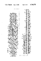
- FIG. 1 is a longitudinal plan view with portions broken away of the multi-conductor lead assembly of the present invention and shows a proximal end of a first lead of the assembly inserted in the epidural space of the spine, a proximal end of a second lead extending into an implanted neural stimulator and a connector assembly in which the proximal end of the first lead and the distal end of the second lead are connected together.
- FIG. 2 is a longitudinal plan view of the proximal end portion of the first lead and the connector assembly withdrawn from tissue.
- FIG. 3 is a longitudinal sectional view of a closure sleeve which is received on the proximal end of the first lead prior to the insertion of the proximal end of the first lead onto a leg of the connector assembly and a clip connector is connected to a selected sleeve electrode after which the closure sleeve is moved over the connector assembly for facilitating a sealed closure over and about the leg and connector clip by the tying of sutures around and adjacent each end of the closure sleeve.
- FIG. 4 is a longitudinal side view of the connector assembly at the distal end of the second lead.
- FIG. 5 on the third sheet of drawings is a longitudinal sectional view through the connector assembly shown in FIG. 4 after the proximal end of the first lead is placed on a rigid leg of the connector assembly and a connector clip at the distal end of a flexible insulated wire conductor is fixed over and on a sleeve electrode on the proximal end portion of the first lead.
- FIG. 6 on the second sheet of drawings is a sectional view through the connector assembly shown in FIG. 5 and is taken along line 6-6 of FIG. 5.
- FIG. 7 is an enlarged perspective view of a section of the proximal end portion of the first lead above two saddle formations on the rigid leg and below the connector clip at the distal end of a flexible insulated wire conductors of the connector assembly.
- FIG. 8 is a longitudinal plan view taken along line 8--8 of FIG. 5 and shows a gripping formation on the distal end portion of the rigid leg of the connector assembly for gripping the proximal end portion of the first lead.
- FIG. 1 there is illustrated a multi-conductor lead assembly 10 constructed according to the teachings of the present invention.
- the assembly 10 includes a first distal lead 12, a second proximal lead 14, and a connector assembly 16 connecting the two leads 12 and 14 together.
- FIG. 1 shows the connector assembly 16 of the present invention in its assembled sealed state mounted within body tissue.
- the first lead 12 includes a lead body 17 having a distal end portion 18 having four ring electrodes 21-24 (or three ring electrodes 21-23 and one tip electrode 24) (FIG. 1) thereon which are positioned within the epidural space of the spine so that at least one of the ring electrodes 21-24 is in a position to supply electrical current signals to nerve tissue for the purpose of interfering with, and blocking, pain signals.
- the electrical current path can be between one ring electrode 21-24 and an anode connected to the body remotely from the position of the ring electrodes 21-24 or between any two of the ring electrodes 21 and 24 when two spring connector clips (92 in FIG. 2) are provided.
- a proximal end portion 30 (FIG. 2) of the first lead 12 hidden from view in FIG. 1 has four sleeve electrodes 31-34 (FIG. 2) which are received in the connector assembly 16.
- the connector assembly 16 is mounted on a distal end portion 38 of the second lead 14.
- the second lead 14 has a proximal end 39 mounting a terminal assembly 40 which has a terminal pin 42.
- the terminal assembly 40 is received in a socket 43 in an implanted neural stimulator 44 for electrically connecting the terminal pin 42 to electrical circuitry within the neural stimulator 44.
- a selected ring electrode 21, 22, 23, or 24 (identified such as by electrical conductivity testing) is connected through the connector assembly 16 to the terminal pin 42.
- the distal end portion 18 of the first lead 16 is inserted into the epidural space in the spine of a body. Then, the proximal end portion 30 of the first lead 12 is brought out of the body, as shown in FIG. 2, so that tests can be made by making connections, such as with alligator clips (not shown) between a conductivity sensor (not shown) and the sleeve electrodes 31-34 to determine the sensitivity or effectiveness of contact of each ring electrode 21-24 of the first lead 12 to the spinal cord. In this way, the ring electrode 21-24 which will be connected via connector assembly 16 to the terminal pin 42 is determined.
- proximal end 30 of the first lead 12 is inserted on a rigid leg 90 (FIG. 4) of the connector assembly 16 and a spring connector clip 92 is snapped over the sleeve electrode 32, 32, 33 or 34 connected to the selected ring electrode 21, 22, 23 or 24.
- a closure sleeve 100 (FIG. 3) is inserted over the proximal end portion 30 of the first lead 12 and far enough up on the lead 12 so that the proximal end portion 30 of the first lead 12 can be inserted on the leg 90 of the connector assembly 16. Then, after the clip 92 is connected to one of the sleeve electrodes 31-34, the closure sleeve 100 is slid back over the connector assembly 16 and sutures 102 and 104 (FIG. 1) are tied around each end 106 and 108 of the sleeve 100 to fix the closure sleeve 100 over the connector assembly 16 and to seal the connections in the connector assembly 16 from body fluids.
- annular rib 114 can be provided within a lumen 116 of the sleeve 100 adjacent the end 106 which is received over the first lead 12 and a similar annular rib 120 can be provided in a larger lumen 122 of the sleeve 100 adjacent the end 108 of the sleeve 100 which is received over a cylindrical body 126 (FIG. 5) of the connector assembly 16 for providing an internal seal between the interior of the sleeve and the body 126 and the first lead 12.
- the connector assembly 16 of the present invention has the distal end portion 38 of the second lead 14 received in a bore 128 in a tapered proximal end portion 130 of the body 126.
- a coiled wire conductor 131 in the second lead 14 extends from the proximal end portion 38 where it is connected to the terminal pin into a finger 132 received in a stepped cavity 134 in the body 126.
- a cylindrical sleeve 136 made of a more rigid plastic material, such as a thermoplastic material.
- This sleeve 136 has an at least partially annular hollow 137 which receives an at least partially annular boss 138 of the finger 132 thereby to prevent relative longitudinal movement between the finger 132 and the cylindrical sleeve 136.
- the body portion 126 has, within the cavity 134, an annular rib 140 which is received in an annular groove 142 on the outer surface of the cylindrical sleeve 136 to prevent relative longitudinal movement between the body 126 and the cylindrical sleeve 136.
- the finger 132 is made of a flexible elastomeric material and has a bore 143 opening onto a proximal end 144 of the finger 132 and extending to an internal end wall 145.
- An inner end portion 146 of the bore 143 is larger in diameter and has a metal sleeve 147 pressed into the inner end portion 146.
- the coiled conductor 131 extends into the bore 143 and into the inner end portion 146 where a proximal end 148 of a wire conductor 149 is positioned between the sleeve 147 and a coiled end portion 150 of the wire conductor 131.
- the sleeve 147, the wire end portion 148 and the coiled wire end portion 150 are soldered together.
- a pin 153 can be inserted as shown in FIG. 5 into the coiled end portion 150 and the entire assembly can be crimped.
- the rigid leg 90 is integral with and extends axially outwardly from the cylindrical sleeve 136 adjacent a partially annular rib 151 at a distal end 152 of the sleeve 136.
- the rigid leg 90 is also made of a hard, stiff, rigid, thermoplastic material.
- the rigid leg 90 has a partially cylindrical outer surface 154 and a flat inner or upper surface 156 with four saddle formations 161-164 extending upwardly from the flat surface 156.
- the saddle formations 161, 162, and 163 are adapted to receive segments of the proximal end portion 30 of the first lead 12 between the spaced apart sleeve electrodes 31-34 thereon.
- the distal saddle formation 164 located at a distal end 166 of the rigid leg 90, includes a first jaw 168 (FIG. 8) and a second jaw 170 (FIG. 8) separated by a slot 172 (FIG. 8).
- the sides of the jaws 168, 170, facing each other on each side of the slot 172 have teeth 174, 176 (FIG. 8) thereon for gripping the proximal end portion 30 of the first lead 12, just distal of the proximal end portion 30 thereof, to assist in holding the proximal end portion 30 of the first lead 12 on the leg 90 of the connector assembly 16.
- the wire conductor 149 extends from its proximal end 148 into and through a flexible elastomeric sheath 180 which can be flexed and raised above the stiff rigid leg 90, as shown in FIGS. 2 and 4 to a distal end 182 which is fixed to the spring connector clip 92.
- the connector clip 92 includes a first leg portion 191, a second leg portion 192 having a free edge 193, and a bight portion 194.
- the first leg portion 191 has a connector leaf or blade 196 integral therewith and extending upwardly generally parallel to the first and second leg portions 191 and 192 to a rounded curled over or bent end portion 197.
- the bare distal end 182 of the wire conductor 149 is received in the curled over or bent end portion 197 of the leaf 196 which is crimped over the uninsulated end 182 to make a mechanical and electrical connection therewith.
- the inside width of the U-shaped connector clip 92 is less than the outer diameter of each of the sleeve electrodes 31-34 so that an interference friction fit is made between the clip 92 and a selected one of the sleeve electrodes 31-34 when the clip 92 is brought down over the proximal end portion 30 of the first lead 12 and against the rigid leg 90.
- the first lead 12 has four insulated coiled wire conductors 201-204 therein.
- a wire conductor 201 in the proximal end portion 30 of the first lead 12 has an uninsulated end portion that is brought out of the lead body 17 to make connection with the sleeve electrode 31.
- the proximal end portions of wire conductors 202, 203, 204 are connected to sleeve electrodes 32, 33 and 34.
- the sensitivity or conductive path between each of the ring electrodes 21, 22, 23 and 24 and adjacent nerve tissues is determined by performing conductivity tests, such as by making selective connections to the sleeve electrodes 31, 32, 33 and 34 on the proximal end portion 30 of the first lead 12 which is withdrawn from the body for this purpose.
- the closure sleeve 100 is inserted over the proximal end portion 30 of the first lead 12. Then the proximal end portion 30 of the first lead 12 is placed on the rigid leg 90 with the sleeve electrodes 31-34 in the spaces between the distal end 200 of the cylindrical sleeve 136 and the saddle formations 161-164. Then the connector clip 92 is squeezed over a selected one of the sleeve electrodes 31, 32, 33 and 34.
- closure sleeve 100 is moved over the leg 90 and the body 126 and the sutures 102 and 104 are tied in place to seal the closure sleeve 100 about the body 26 and legs 91 and 92 of the connector assembly 16 and particularly about the first and second legs 90 with the proximal end portion 30 of the first lead 12 thereon.
- the sutures 102 and 104 are tied about the respective ends 106 and 108 of the closure sleeve 100 to seal the connector assembly 16, after which the connector assembly 16 is implanted within body tissue as shown in FIG. 1.
- the multi-conductor neural stimulating assembly 10 of the present invention and particularly the connector assembly 16 thereof have a number of advantages some of which have been described above and others of which are inherent in the invention.
- the simple and easy way of connecting the proximal end portion 30 of the first lead 12 to the connector assembly 16 and the sealing of same enables testing of the sensitivity or threshold level of each ring electrode 21, 22, 23 and 24 adjacent nerve tissue in the epidural space within the spine of the body prior to connection of the lead 12 to the lead 14.
- the stimulating assembly 10 is particularly adapted for relatively permanent implantation after testing has been effected with a temporary lead assembly of the type disclosed and claimed in copending application Ser. No. 042,834, filed on Apr. 27, 1987 for: MULTI-CONDUCTOR LEAD ASSEMBLY FOR TEMPORARY USE.
- a second spring clip 92 can be provided as shown in FIG. 2 to provide a bipolar assembly. Accordingly, the scope of the invention is only to be limited as necessitated by the accompanying claims.
Abstract
Description
Claims (13)
Priority Applications (1)
| Application Number | Priority Date | Filing Date | Title |
|---|---|---|---|
| US07/042,677 US4744370A (en) | 1987-04-27 | 1987-04-27 | Lead assembly with selectable electrode connection |
Applications Claiming Priority (1)
| Application Number | Priority Date | Filing Date | Title |
|---|---|---|---|
| US07/042,677 US4744370A (en) | 1987-04-27 | 1987-04-27 | Lead assembly with selectable electrode connection |
Publications (1)
| Publication Number | Publication Date |
|---|---|
| US4744370A true US4744370A (en) | 1988-05-17 |
Family
ID=21923184
Family Applications (1)
| Application Number | Title | Priority Date | Filing Date |
|---|---|---|---|
| US07/042,677 Expired - Lifetime US4744370A (en) | 1987-04-27 | 1987-04-27 | Lead assembly with selectable electrode connection |
Country Status (1)
| Country | Link |
|---|---|
| US (1) | US4744370A (en) |
Cited By (86)
| Publication number | Priority date | Publication date | Assignee | Title |
|---|---|---|---|---|
| DE8906745U1 (en) * | 1989-06-02 | 1989-09-21 | Vascomed Gmbh, 7858 Weil, De | |
| US4961422A (en) * | 1983-01-21 | 1990-10-09 | Marchosky J Alexander | Method and apparatus for volumetric interstitial conductive hyperthermia |
| US4989601A (en) * | 1988-05-02 | 1991-02-05 | Medical Engineering & Development Institute, Inc. | Method, apparatus, and substance for treating tissue having neoplastic cells |
| US5354326A (en) * | 1993-01-27 | 1994-10-11 | Medtronic, Inc. | Screening cable connector for interface to implanted lead |
| US5824030A (en) * | 1995-12-21 | 1998-10-20 | Pacesetter, Inc. | Lead with inter-electrode spacing adjustment |
| US20020138105A1 (en) * | 2001-03-21 | 2002-09-26 | Kralik Michael R. | Temporary biventricular pacing of heart after heart surgery |
| US20020183817A1 (en) * | 2000-12-07 | 2002-12-05 | Paul Van Venrooij | Directional brain stimulation and recording leads |
| US20030229387A1 (en) * | 2000-02-08 | 2003-12-11 | Medtronic, Inc. | Surgical lead body |
| US6666864B2 (en) * | 2001-06-29 | 2003-12-23 | Scimed Life Systems, Inc. | Electrophysiological probes having selective element actuation and variable lesion length capability |
| WO2004007014A1 (en) * | 2002-07-17 | 2004-01-22 | Khalil Karima H | Transmit time thermodilution guidewire system for measuring coronary blood flow velocity |
| US20040230268A1 (en) * | 2003-05-13 | 2004-11-18 | Medtronic, Inc. | Medical lead adaptor assembly |
| US20050177199A1 (en) * | 2004-02-09 | 2005-08-11 | Cardiac Pacemakers, Inc. | PSA cable and connector for quadripolar lead terminal |
| US20060168805A1 (en) * | 2005-01-31 | 2006-08-03 | Michael Hegland | Method of manufacturing a medical lead |
| US20060258193A1 (en) * | 2005-05-12 | 2006-11-16 | Cardiac Pacemakers, Inc. | Lead terminal multi-tool |
| US20100268298A1 (en) * | 2009-04-16 | 2010-10-21 | Boston Scientific Neuromodulation Corporation | Deep brain stimulation current steering with split electrodes |
| US20110009932A1 (en) * | 2009-07-08 | 2011-01-13 | Boston Scientific Neuromodulation Corporation | Systems and methods of making and using support elements for elongated members of implantable electric stimulation systems |
| US20110005069A1 (en) * | 2009-07-07 | 2011-01-13 | Boston Scientific Neuromodulation Corporation | Systems and leads with a radially segmented electrode array and methods of manufacture |
| US20110078900A1 (en) * | 2009-07-07 | 2011-04-07 | Boston Scientific Neuromodulation Corporation | Methods for making leads with radially-aligned segmented electrodes for electrical stimulation systems |
| US20110130803A1 (en) * | 2009-11-30 | 2011-06-02 | Boston Scientific Neuromodulation Corporation | Electrode array having concentric windowed cylinder electrodes and methods of making the same |
| US20110130816A1 (en) * | 2009-11-30 | 2011-06-02 | Boston Scientific Neuromodulation Corporation | Electrode array with electrodes having cutout portions and methods of making the same |
| US20110178575A1 (en) * | 2008-09-10 | 2011-07-21 | Cryer Adrian R | Insulated electrical connection in an implantable medical device |
| US20110218605A1 (en) * | 2008-09-10 | 2011-09-08 | Adrian Cryer | Upgradeable implantable device |
| US20110238129A1 (en) * | 2010-03-23 | 2011-09-29 | Boston Scientific Neuromodulation Corporation | Helical radial spacing of contacts on a cylindrical lead |
| US20120232627A1 (en) * | 2011-03-11 | 2012-09-13 | Greatbatch Ltd. | Pre-sutured anchor for implantable leads |
| US8560085B2 (en) | 2011-02-08 | 2013-10-15 | Boston Scientific Neuromodulation Corporation | Methods for making leads with segmented electrodes for electrical stimulation systems |
| JP2013543402A (en) * | 2010-11-19 | 2013-12-05 | カーディアック ペースメイカーズ, インコーポレイテッド | Peel-away IS-4 / DF-4 lead implantation tool with electrical contacts |
| US8649879B2 (en) | 2011-02-08 | 2014-02-11 | Boston Scientific Neuromodulation Corporation | Leads with retention features for segmented electrodes and methods of making and using the leads |
| US8694127B2 (en) | 2010-09-21 | 2014-04-08 | Boston Scientific Neuromodulation Corporation | Systems and methods for making and using radially-aligned segmented electrodes for leads of electrical stimulation systems |
| US8700179B2 (en) | 2011-02-02 | 2014-04-15 | Boston Scientific Neuromodulation Corporation | Leads with spiral of helical segmented electrode arrays and methods of making and using the leads |
| US8744596B2 (en) | 2012-03-30 | 2014-06-03 | Boston Scientific Neuromodulation Corporation | Leads with X-ray fluorescent capsules for electrode identification and methods of manufacture and use |
| US8788063B2 (en) | 2009-11-30 | 2014-07-22 | Boston Scientific Neuromodulation Corporation | Electrode array having a rail system and methods of manufacturing the same |
| US8792993B2 (en) | 2012-06-01 | 2014-07-29 | Boston Scientific, Neuromodulation Corporation | Leads with tip electrode for electrical stimulation systems and methods of making and using |
| US8805519B2 (en) | 2010-09-30 | 2014-08-12 | Nevro Corporation | Systems and methods for detecting intrathecal penetration |
| US8831742B2 (en) | 2012-01-26 | 2014-09-09 | Boston Scientific Neuromodulation Corporation | Systems and methods for identifying the circumferential positioning of electrodes of leads for electrical stimulation systems |
| US8849415B2 (en) | 2006-07-31 | 2014-09-30 | Boston Scientific Neuromodulation Corporation | Multi-channel connector for brain stimulation system |
| US8862242B2 (en) | 2010-12-23 | 2014-10-14 | Boston Scientific Neuromodulation Corporation | Methods for making leads with segmented electrodes for electrical stimulation systems |
| US8868206B2 (en) | 2010-06-18 | 2014-10-21 | Boston Scientific Neuromodulation Corporation | Electrode array having embedded electrodes and methods of making the same |
| US8874232B2 (en) | 2009-11-30 | 2014-10-28 | Boston Scientific Neuromodulation Corporation | Electrode array having concentric split ring electrodes and methods of making the same |
| US8897891B2 (en) | 2012-08-03 | 2014-11-25 | Boston Scientific Neuromodulation Corporation | Leads with electrode carrier for segmented electrodes and methods of making and using |
| US8897889B2 (en) | 2008-10-09 | 2014-11-25 | Boston Scientific Neuromodulation Corporation | Electrode design for leads of implantable electric stimulation systems and methods of making and using |
| US8965482B2 (en) | 2010-09-30 | 2015-02-24 | Nevro Corporation | Systems and methods for positioning implanted devices in a patient |
| US9089689B2 (en) | 2013-08-30 | 2015-07-28 | Boston Scientific Neuromodulation Corporation | Methods of making segmented electrode leads using flanged carrier |
| US9149630B2 (en) | 2013-05-31 | 2015-10-06 | Boston Scientific Neuromodulation Corporation | Segmented electrode leads formed from pre-electrodes with alignment features and methods of making and using the leads |
| US9162049B2 (en) | 2010-09-13 | 2015-10-20 | Boston Scientific Neuromodulation Corporation | Devices and methods for tissue modulation and monitoring |
| US9162048B2 (en) | 2013-05-15 | 2015-10-20 | Boston Scientific Neuromodulation Corporation | Systems and methods for making and using tip electrodes for leads of electrical stimulation systems |
| US9248272B2 (en) | 2013-05-31 | 2016-02-02 | Boston Scientific Neuromodulation Corporation | Segmented electrode leads formed from pre-electrodes with depressions or apertures and methods of making and using |
| US9283394B2 (en) | 2002-06-20 | 2016-03-15 | Boston Scientific Neuromodulation Corporation | Implantable microstimulators and methods for unidirectional propagation of action potentials |
| US9283375B2 (en) | 2011-02-08 | 2016-03-15 | Boston Scientific Neuromodulation Corporation | Leads with segmented electrodes for electrical stimulation of planar regions and methods of making and using |
| US9289596B2 (en) | 2013-07-12 | 2016-03-22 | Boston Scientific Neuromodulation Corporation | Leads with segmented electrodes and methods of making and using the leads |
| US9314614B2 (en) | 2006-07-31 | 2016-04-19 | Boston Scientific Neuromodulation Corporation | Lead and methods for brain monitoring and modulation |
| US9381348B2 (en) | 2013-05-31 | 2016-07-05 | Boston Scientific Neuromodulation Corporation | Leads with segmented electrodes and methods of making and using the leads |
| US9498620B2 (en) | 2013-05-31 | 2016-11-22 | Boston Scientific Neuromodulation Corporation | Leads containing segmented electrodes with non-perpendicular legs and methods of making and using |
| US9561362B2 (en) | 2014-11-10 | 2017-02-07 | Boston Scientific Neuromodulation Corporation | Systems and methods for making and using improved contact arrays for electrical stimulation systems |
| US9566747B2 (en) | 2013-07-22 | 2017-02-14 | Boston Scientific Neuromodulation Corporation | Method of making an electrical stimulation lead |
| US9604068B2 (en) | 2014-11-10 | 2017-03-28 | Boston Scientific Neuromodulation Corporation | Systems and methods for making and using improved connector contacts for electrical stimulation systems |
| US9656093B2 (en) | 2015-07-16 | 2017-05-23 | Boston Scientific Neuromodulation Corporation | Systems and methods for making and using connector contact arrays for electrical stimulation systems |
| US9675795B2 (en) | 2010-07-16 | 2017-06-13 | Boston Scientific Neuromodulation Corporation | Systems and methods for radial steering of electrode arrays |
| US9770598B2 (en) | 2014-08-29 | 2017-09-26 | Boston Scientific Neuromodulation Corporation | Systems and methods for making and using improved connector contacts for electrical stimulation systems |
| US9775988B2 (en) | 2013-12-02 | 2017-10-03 | Boston Scientific Neuromodulation Corporation | Electrical stimulation leads with helically arranged electrodes and methods of making and using |
| US9833611B2 (en) | 2015-04-10 | 2017-12-05 | Boston Scientific Neuromodulation Corporation | Systems and methods for making and using improved contact arrays for electrical stimulation systems |
| US9956394B2 (en) | 2015-09-10 | 2018-05-01 | Boston Scientific Neuromodulation Corporation | Connectors for electrical stimulation systems and methods of making and using |
| US9962541B2 (en) | 2014-06-13 | 2018-05-08 | Boston Scientific Neuromodulation Corporation | Leads with electrode carriers for segmented electrodes and methods of making and using |
| US10172465B2 (en) | 2013-03-15 | 2019-01-08 | Hni Technologies Inc. | Chair with activated back flex |
| US10201713B2 (en) | 2016-06-20 | 2019-02-12 | Boston Scientific Neuromodulation Corporation | Threaded connector assembly and methods of making and using the same |
| US10286205B2 (en) | 2015-02-06 | 2019-05-14 | Boston Scientific Neuromodulation Corporation | Systems and methods for making and using improved contact arrays for electrical stimulation systems |
| US10307602B2 (en) | 2016-07-08 | 2019-06-04 | Boston Scientific Neuromodulation Corporation | Threaded connector assembly and methods of making and using the same |
| US10342983B2 (en) | 2016-01-14 | 2019-07-09 | Boston Scientific Neuromodulation Corporation | Systems and methods for making and using connector contact arrays for electrical stimulation systems |
| US10413737B2 (en) | 2015-09-25 | 2019-09-17 | Boston Scientific Neuromodulation Corporation | Systems and methods for providing therapy using electrical stimulation to disrupt neuronal activity |
| US10543374B2 (en) | 2016-09-30 | 2020-01-28 | Boston Scientific Neuromodulation Corporation | Connector assemblies with bending limiters for electrical stimulation systems and methods of making and using same |
| US10576269B2 (en) | 2017-01-03 | 2020-03-03 | Boston Scientific Neuromodulation Corporation | Force-decoupled and strain relieving lead and methods of making and using |
| US10603499B2 (en) | 2017-04-07 | 2020-03-31 | Boston Scientific Neuromodulation Corporation | Tapered implantable lead and connector interface and methods of making and using |
| US10639485B2 (en) | 2017-09-15 | 2020-05-05 | Boston Scientific Neuromodulation Corporation | Actuatable lead connector for an operating room cable assembly and methods of making and using |
| US10814136B2 (en) | 2017-02-28 | 2020-10-27 | Boston Scientific Neuromodulation Corporation | Toolless connector for latching stimulation leads and methods of making and using |
| US10905871B2 (en) | 2017-01-27 | 2021-02-02 | Boston Scientific Neuromodulation Corporation | Lead assemblies with arrangements to confirm alignment between terminals and contacts |
| US10918873B2 (en) | 2017-07-25 | 2021-02-16 | Boston Scientific Neuromodulation Corporation | Systems and methods for making and using an enhanced connector of an electrical stimulation system |
| US10980999B2 (en) | 2017-03-09 | 2021-04-20 | Nevro Corp. | Paddle leads and delivery tools, and associated systems and methods |
| US11045656B2 (en) | 2017-09-15 | 2021-06-29 | Boston Scientific Neuromodulation Corporation | Biased lead connector for operating room cable assembly and methods of making and using |
| US11052259B2 (en) | 2018-05-11 | 2021-07-06 | Boston Scientific Neuromodulation Corporation | Connector assembly for an electrical stimulation system and methods of making and using |
| US11071869B2 (en) | 2016-02-24 | 2021-07-27 | Cochlear Limited | Implantable device having removable portion |
| US11103712B2 (en) | 2018-01-16 | 2021-08-31 | Boston Scientific Neuromodulation Corporation | Connector assemblies with novel spacers for electrical stimulation systems and methods of making and using same |
| US11139603B2 (en) | 2017-10-03 | 2021-10-05 | Boston Scientific Neuromodulation Corporation | Connectors with spring contacts for electrical stimulation systems and methods of making and using same |
| US11167128B2 (en) | 2018-11-16 | 2021-11-09 | Boston Scientific Neuromodulation Corporation | Directional electrical stimulation leads, systems and methods for spinal cord stimulation |
| US11172959B2 (en) | 2018-05-02 | 2021-11-16 | Boston Scientific Neuromodulation Corporation | Long, flexible sheath and lead blank and systems and methods of making and using |
| US11357992B2 (en) | 2019-05-03 | 2022-06-14 | Boston Scientific Neuromodulation Corporation | Connector assembly for an electrical stimulation system and methods of making and using |
| US11420045B2 (en) | 2018-03-29 | 2022-08-23 | Nevro Corp. | Leads having sidewall openings, and associated systems and methods |
| US11951317B2 (en) | 2021-06-09 | 2024-04-09 | Boston Scientific Neuromodulation Corporation | Biased lead connector for operating room cable assembly and methods of making and using |
Citations (8)
| Publication number | Priority date | Publication date | Assignee | Title |
|---|---|---|---|---|
| US3291926A (en) * | 1963-03-18 | 1966-12-13 | Winsco Instr & Controls Compan | Fluid proof switch |
| US3546657A (en) * | 1968-07-29 | 1970-12-08 | North American Rockwell | High contact density underwater connector |
| US4379462A (en) * | 1980-10-29 | 1983-04-12 | Neuromed, Inc. | Multi-electrode catheter assembly for spinal cord stimulation |
| US4628934A (en) * | 1984-08-07 | 1986-12-16 | Cordis Corporation | Method and means of electrode selection for pacemaker with multielectrode leads |
| US4630611A (en) * | 1981-02-02 | 1986-12-23 | Medtronic, Inc. | Orthogonally-sensing lead |
| US4644960A (en) * | 1985-09-23 | 1987-02-24 | Arrow International, Inc. | Device for making electrical connection to an electrolyte, and system employing same |
| US4667686A (en) * | 1985-05-16 | 1987-05-26 | Cordis Corporation | Pacer lead terminal assembly |
| US4672979A (en) * | 1986-01-30 | 1987-06-16 | Cordis Corporation | Suture sleeve assembly |
-
1987
- 1987-04-27 US US07/042,677 patent/US4744370A/en not_active Expired - Lifetime
Patent Citations (8)
| Publication number | Priority date | Publication date | Assignee | Title |
|---|---|---|---|---|
| US3291926A (en) * | 1963-03-18 | 1966-12-13 | Winsco Instr & Controls Compan | Fluid proof switch |
| US3546657A (en) * | 1968-07-29 | 1970-12-08 | North American Rockwell | High contact density underwater connector |
| US4379462A (en) * | 1980-10-29 | 1983-04-12 | Neuromed, Inc. | Multi-electrode catheter assembly for spinal cord stimulation |
| US4630611A (en) * | 1981-02-02 | 1986-12-23 | Medtronic, Inc. | Orthogonally-sensing lead |
| US4628934A (en) * | 1984-08-07 | 1986-12-16 | Cordis Corporation | Method and means of electrode selection for pacemaker with multielectrode leads |
| US4667686A (en) * | 1985-05-16 | 1987-05-26 | Cordis Corporation | Pacer lead terminal assembly |
| US4644960A (en) * | 1985-09-23 | 1987-02-24 | Arrow International, Inc. | Device for making electrical connection to an electrolyte, and system employing same |
| US4672979A (en) * | 1986-01-30 | 1987-06-16 | Cordis Corporation | Suture sleeve assembly |
Cited By (141)
| Publication number | Priority date | Publication date | Assignee | Title |
|---|---|---|---|---|
| US4961422A (en) * | 1983-01-21 | 1990-10-09 | Marchosky J Alexander | Method and apparatus for volumetric interstitial conductive hyperthermia |
| US5197466A (en) * | 1983-01-21 | 1993-03-30 | Med Institute Inc. | Method and apparatus for volumetric interstitial conductive hyperthermia |
| US4989601A (en) * | 1988-05-02 | 1991-02-05 | Medical Engineering & Development Institute, Inc. | Method, apparatus, and substance for treating tissue having neoplastic cells |
| DE8906745U1 (en) * | 1989-06-02 | 1989-09-21 | Vascomed Gmbh, 7858 Weil, De | |
| US5354326A (en) * | 1993-01-27 | 1994-10-11 | Medtronic, Inc. | Screening cable connector for interface to implanted lead |
| US5824030A (en) * | 1995-12-21 | 1998-10-20 | Pacesetter, Inc. | Lead with inter-electrode spacing adjustment |
| US20030229387A1 (en) * | 2000-02-08 | 2003-12-11 | Medtronic, Inc. | Surgical lead body |
| US7319904B2 (en) | 2000-02-08 | 2008-01-15 | Medtronic, Inc. | Percutaneous Surgical lead body |
| US7212867B2 (en) | 2000-12-07 | 2007-05-01 | Medtronic, Inc. | Directional brain stimulation and recording leads |
| US20020183817A1 (en) * | 2000-12-07 | 2002-12-05 | Paul Van Venrooij | Directional brain stimulation and recording leads |
| US20020138105A1 (en) * | 2001-03-21 | 2002-09-26 | Kralik Michael R. | Temporary biventricular pacing of heart after heart surgery |
| US7010350B2 (en) * | 2001-03-21 | 2006-03-07 | Kralik Michael R | Temporary biventricular pacing of heart after heart surgery |
| US6666864B2 (en) * | 2001-06-29 | 2003-12-23 | Scimed Life Systems, Inc. | Electrophysiological probes having selective element actuation and variable lesion length capability |
| US9283394B2 (en) | 2002-06-20 | 2016-03-15 | Boston Scientific Neuromodulation Corporation | Implantable microstimulators and methods for unidirectional propagation of action potentials |
| WO2004007014A1 (en) * | 2002-07-17 | 2004-01-22 | Khalil Karima H | Transmit time thermodilution guidewire system for measuring coronary blood flow velocity |
| US7130699B2 (en) * | 2003-05-13 | 2006-10-31 | Medtronic, Inc. | Medical lead adaptor assembly |
| US20040230268A1 (en) * | 2003-05-13 | 2004-11-18 | Medtronic, Inc. | Medical lead adaptor assembly |
| US20050177199A1 (en) * | 2004-02-09 | 2005-08-11 | Cardiac Pacemakers, Inc. | PSA cable and connector for quadripolar lead terminal |
| US20060168805A1 (en) * | 2005-01-31 | 2006-08-03 | Michael Hegland | Method of manufacturing a medical lead |
| US20060173262A1 (en) * | 2005-01-31 | 2006-08-03 | Medtronic, Inc. | Medical lead with segmented electrode |
| US8739403B2 (en) | 2005-01-31 | 2014-06-03 | Medtronic, Inc. | Method of manufacturing a medical lead |
| US7761985B2 (en) | 2005-01-31 | 2010-07-27 | Medtronic, Inc. | Method of manufacturing a medical lead |
| US8000808B2 (en) | 2005-01-31 | 2011-08-16 | Medtronic, Inc. | Medical lead with segmented electrode |
| US20060258193A1 (en) * | 2005-05-12 | 2006-11-16 | Cardiac Pacemakers, Inc. | Lead terminal multi-tool |
| US7753696B2 (en) | 2005-05-12 | 2010-07-13 | Cardiac Pacemakers, Inc. | Lead terminal multi-tool |
| US9314614B2 (en) | 2006-07-31 | 2016-04-19 | Boston Scientific Neuromodulation Corporation | Lead and methods for brain monitoring and modulation |
| US8849415B2 (en) | 2006-07-31 | 2014-09-30 | Boston Scientific Neuromodulation Corporation | Multi-channel connector for brain stimulation system |
| US10166385B2 (en) | 2006-07-31 | 2019-01-01 | Boston Scientific Neuromodulation Corporation | Lead and methods for brain monitoring and modulation |
| US20110218605A1 (en) * | 2008-09-10 | 2011-09-08 | Adrian Cryer | Upgradeable implantable device |
| US20160235993A1 (en) * | 2008-09-10 | 2016-08-18 | Adrian Robert Cryer | Insulated electrical connection in an implantable medical device |
| US20110178575A1 (en) * | 2008-09-10 | 2011-07-21 | Cryer Adrian R | Insulated electrical connection in an implantable medical device |
| US8897889B2 (en) | 2008-10-09 | 2014-11-25 | Boston Scientific Neuromodulation Corporation | Electrode design for leads of implantable electric stimulation systems and methods of making and using |
| US8473061B2 (en) | 2009-04-16 | 2013-06-25 | Boston Scientific Neuromodulation Corporation | Deep brain stimulation current steering with split electrodes |
| US9393403B2 (en) | 2009-04-16 | 2016-07-19 | Boston Scientific Neuromodulation Corporation | Deep brain stimulation current steering with split electrodes |
| US8649873B2 (en) | 2009-04-16 | 2014-02-11 | Boston Scientific Neuromodulation Corporation | Deep brain stimulation current steering with split electrodes |
| US20100268298A1 (en) * | 2009-04-16 | 2010-10-21 | Boston Scientific Neuromodulation Corporation | Deep brain stimulation current steering with split electrodes |
| US9211402B2 (en) | 2009-04-16 | 2015-12-15 | Boston Scientific Neuromodulation Corporation | Deep brain stimulation current steering with split electrodes |
| US8914121B2 (en) | 2009-04-16 | 2014-12-16 | Boston Scientific Neuromodulation Corporation | Deep brain stimulation current steering with split electrodes |
| US9270070B2 (en) | 2009-07-07 | 2016-02-23 | Boston Scientific Neuromodulation Corporation | Methods of manufacturing leads with a radially segmented electrode array |
| US20110005069A1 (en) * | 2009-07-07 | 2011-01-13 | Boston Scientific Neuromodulation Corporation | Systems and leads with a radially segmented electrode array and methods of manufacture |
| US20110078900A1 (en) * | 2009-07-07 | 2011-04-07 | Boston Scientific Neuromodulation Corporation | Methods for making leads with radially-aligned segmented electrodes for electrical stimulation systems |
| US9913974B2 (en) | 2009-07-07 | 2018-03-13 | Boston Scientific Neuromodulation Corporation | Methods for making leads with radially-aligned segmented electrodes for electrical stimulation systems |
| US10720729B2 (en) | 2009-07-07 | 2020-07-21 | Boston Scientific Neuromodulation Corporation | Systems and leads with a radially segmented electrode array and methods of manufacture |
| US8875391B2 (en) | 2009-07-07 | 2014-11-04 | Boston Scientific Neuromodulation Corporation | Methods for making leads with radially-aligned segmented electrodes for electrical stimulation systems |
| US8887387B2 (en) | 2009-07-07 | 2014-11-18 | Boston Scientific Neuromodulation Corporation | Methods of manufacture of leads with a radially segmented electrode array |
| US8340782B2 (en) | 2009-07-08 | 2012-12-25 | Boston Scientific Neuromodulation Corporation | Systems and methods of making and using support elements for elongated members of implantable electric stimulation systems |
| US20110009932A1 (en) * | 2009-07-08 | 2011-01-13 | Boston Scientific Neuromodulation Corporation | Systems and methods of making and using support elements for elongated members of implantable electric stimulation systems |
| US8612023B2 (en) | 2009-07-08 | 2013-12-17 | Boston Scientific Neuromodulation Corporation | Systems and methods of making and using support elements for elongated members of implantable electric stimulation systems |
| US8391985B2 (en) | 2009-11-30 | 2013-03-05 | Boston Scientific Neuromodulation Corporation | Electrode array having concentric windowed cylinder electrodes and methods of making the same |
| US9248277B2 (en) | 2009-11-30 | 2016-02-02 | Boston Scientific Neuromodulation Corporation | Electrode array having concentric split ring electrodes and methods of making the same |
| US8442654B2 (en) | 2009-11-30 | 2013-05-14 | Boston Scientific Neuromodulation Corporation | Electrode array with electrodes having cutout portions and methods of making the same |
| US8874232B2 (en) | 2009-11-30 | 2014-10-28 | Boston Scientific Neuromodulation Corporation | Electrode array having concentric split ring electrodes and methods of making the same |
| US8788063B2 (en) | 2009-11-30 | 2014-07-22 | Boston Scientific Neuromodulation Corporation | Electrode array having a rail system and methods of manufacturing the same |
| US8560074B2 (en) | 2009-11-30 | 2013-10-15 | Boston Scientific Neuromodulation Corporation | Electrode array having concentric windowed cylinder electrodes and methods of making the same |
| US8666509B2 (en) | 2009-11-30 | 2014-03-04 | Boston Scientific Neuromodulation Corporation | Electrode array with electrodes having cutout portions and methods of making the same |
| US20110130816A1 (en) * | 2009-11-30 | 2011-06-02 | Boston Scientific Neuromodulation Corporation | Electrode array with electrodes having cutout portions and methods of making the same |
| US20110130803A1 (en) * | 2009-11-30 | 2011-06-02 | Boston Scientific Neuromodulation Corporation | Electrode array having concentric windowed cylinder electrodes and methods of making the same |
| US8295944B2 (en) | 2009-11-30 | 2012-10-23 | Boston Scientific Neuromodulation Corporation | Electrode array with electrodes having cutout portions and methods of making the same |
| US9168369B2 (en) | 2009-11-30 | 2015-10-27 | Boston Scientific Neuromodulation Corporation | Electrode array having a rail system and methods of manufacturing the same |
| US8571665B2 (en) | 2010-03-23 | 2013-10-29 | Boston Scientific Neuromodulation Corporation | Helical radial spacing of contacts on a cylindrical lead |
| US20110238129A1 (en) * | 2010-03-23 | 2011-09-29 | Boston Scientific Neuromodulation Corporation | Helical radial spacing of contacts on a cylindrical lead |
| US20110288614A1 (en) * | 2010-05-21 | 2011-11-24 | Cryer Adrian R | Insulated electrical connection in an implantable medical device |
| US9855417B2 (en) | 2010-06-18 | 2018-01-02 | Boston Scientific Neuromodulation Corporation | Method of making an electrode array having embedded electrodes |
| US8868206B2 (en) | 2010-06-18 | 2014-10-21 | Boston Scientific Neuromodulation Corporation | Electrode array having embedded electrodes and methods of making the same |
| US9675795B2 (en) | 2010-07-16 | 2017-06-13 | Boston Scientific Neuromodulation Corporation | Systems and methods for radial steering of electrode arrays |
| US9162049B2 (en) | 2010-09-13 | 2015-10-20 | Boston Scientific Neuromodulation Corporation | Devices and methods for tissue modulation and monitoring |
| US9795779B2 (en) | 2010-09-21 | 2017-10-24 | Boston Scientific Neuromodulation Corporation | Systems and methods for making and using radially-aligned segmented electrodes for leads of electrical stimulation systems |
| US8694127B2 (en) | 2010-09-21 | 2014-04-08 | Boston Scientific Neuromodulation Corporation | Systems and methods for making and using radially-aligned segmented electrodes for leads of electrical stimulation systems |
| US8805519B2 (en) | 2010-09-30 | 2014-08-12 | Nevro Corporation | Systems and methods for detecting intrathecal penetration |
| US8965482B2 (en) | 2010-09-30 | 2015-02-24 | Nevro Corporation | Systems and methods for positioning implanted devices in a patient |
| US11382531B2 (en) | 2010-09-30 | 2022-07-12 | Nevro Corp. | Systems and methods for positioning implanted devices in a patient |
| US9358388B2 (en) | 2010-09-30 | 2016-06-07 | Nevro Corporation | Systems and methods for detecting intrathecal penetration |
| US9345891B2 (en) | 2010-09-30 | 2016-05-24 | Nevro Corporation | Systems and methods for positioning implanted devices in a patient |
| US10279183B2 (en) | 2010-09-30 | 2019-05-07 | Nevro Corp. | Systems and methods for detecting intrathecal penetration |
| JP2013543402A (en) * | 2010-11-19 | 2013-12-05 | カーディアック ペースメイカーズ, インコーポレイテッド | Peel-away IS-4 / DF-4 lead implantation tool with electrical contacts |
| US8792997B2 (en) | 2010-11-19 | 2014-07-29 | Cardiac Pacemakers, Inc. | Peel-away is-4/DF-4 lead implant tool with electrical contacts |
| US8862242B2 (en) | 2010-12-23 | 2014-10-14 | Boston Scientific Neuromodulation Corporation | Methods for making leads with segmented electrodes for electrical stimulation systems |
| US9295830B2 (en) | 2010-12-23 | 2016-03-29 | Boston Scientific Neuromodulation Corporation | Methods for making leads with segmented electrodes for electrical stimulation systems |
| US8700179B2 (en) | 2011-02-02 | 2014-04-15 | Boston Scientific Neuromodulation Corporation | Leads with spiral of helical segmented electrode arrays and methods of making and using the leads |
| US9248276B2 (en) | 2011-02-02 | 2016-02-02 | Boston Scientific Neuromodulation Corporation | Leads with spiral of helical segmented electrode arrays and methods of making and using the leads |
| US9283375B2 (en) | 2011-02-08 | 2016-03-15 | Boston Scientific Neuromodulation Corporation | Leads with segmented electrodes for electrical stimulation of planar regions and methods of making and using |
| US8560085B2 (en) | 2011-02-08 | 2013-10-15 | Boston Scientific Neuromodulation Corporation | Methods for making leads with segmented electrodes for electrical stimulation systems |
| US9248275B2 (en) | 2011-02-08 | 2016-02-02 | Boston Scientific Neuromodulation Corporation | Methods of making leads with retention features for segmented electrodes |
| US8649879B2 (en) | 2011-02-08 | 2014-02-11 | Boston Scientific Neuromodulation Corporation | Leads with retention features for segmented electrodes and methods of making and using the leads |
| US8437846B2 (en) * | 2011-03-11 | 2013-05-07 | Greatbatch Ltd. | Pre-sutured anchor for implantable leads |
| US20120232627A1 (en) * | 2011-03-11 | 2012-09-13 | Greatbatch Ltd. | Pre-sutured anchor for implantable leads |
| US8886303B1 (en) | 2011-03-11 | 2014-11-11 | Greatbatch, Ltd. | Pre-sutured anchor for implantable leads |
| US8831742B2 (en) | 2012-01-26 | 2014-09-09 | Boston Scientific Neuromodulation Corporation | Systems and methods for identifying the circumferential positioning of electrodes of leads for electrical stimulation systems |
| US8923982B2 (en) | 2012-03-30 | 2014-12-30 | Boston Scientific Neuromodulation Corporation | Leads with X-ray fluorescent capsules for electrode identification and methods of manufacture and use |
| US8744596B2 (en) | 2012-03-30 | 2014-06-03 | Boston Scientific Neuromodulation Corporation | Leads with X-ray fluorescent capsules for electrode identification and methods of manufacture and use |
| US8996132B2 (en) | 2012-06-01 | 2015-03-31 | Boston Scientific Neuromodulation Corporation | Leads with tip electrode for electrical stimulation systems and methods of making and using |
| US8792993B2 (en) | 2012-06-01 | 2014-07-29 | Boston Scientific, Neuromodulation Corporation | Leads with tip electrode for electrical stimulation systems and methods of making and using |
| US9427567B2 (en) | 2012-08-03 | 2016-08-30 | Boston Scientific Neuromodulation Corporation | Leads with electrode carrier for segmented electrodes and methods of making and using |
| US8897891B2 (en) | 2012-08-03 | 2014-11-25 | Boston Scientific Neuromodulation Corporation | Leads with electrode carrier for segmented electrodes and methods of making and using |
| US9227050B2 (en) | 2012-08-03 | 2016-01-05 | Boston Scientific Neuromodulation Corporation | Leads with electrode carrier for segmented electrodes and methods of making and using |
| US10172465B2 (en) | 2013-03-15 | 2019-01-08 | Hni Technologies Inc. | Chair with activated back flex |
| US9616220B2 (en) | 2013-05-15 | 2017-04-11 | Boston Scientific Neuromodulation Corporation | Systems and methods for making and using tip electrodes for leads of electrical stimulation systems |
| US9162048B2 (en) | 2013-05-15 | 2015-10-20 | Boston Scientific Neuromodulation Corporation | Systems and methods for making and using tip electrodes for leads of electrical stimulation systems |
| US9149630B2 (en) | 2013-05-31 | 2015-10-06 | Boston Scientific Neuromodulation Corporation | Segmented electrode leads formed from pre-electrodes with alignment features and methods of making and using the leads |
| US9248272B2 (en) | 2013-05-31 | 2016-02-02 | Boston Scientific Neuromodulation Corporation | Segmented electrode leads formed from pre-electrodes with depressions or apertures and methods of making and using |
| US9381348B2 (en) | 2013-05-31 | 2016-07-05 | Boston Scientific Neuromodulation Corporation | Leads with segmented electrodes and methods of making and using the leads |
| US9381347B2 (en) | 2013-05-31 | 2016-07-05 | Boston Scientific Neuromodulation Corporation | Segmented electrode leads formed from pre-electrodes with alignment features and methods of making and using the leads |
| US9498620B2 (en) | 2013-05-31 | 2016-11-22 | Boston Scientific Neuromodulation Corporation | Leads containing segmented electrodes with non-perpendicular legs and methods of making and using |
| US9289596B2 (en) | 2013-07-12 | 2016-03-22 | Boston Scientific Neuromodulation Corporation | Leads with segmented electrodes and methods of making and using the leads |
| US9566747B2 (en) | 2013-07-22 | 2017-02-14 | Boston Scientific Neuromodulation Corporation | Method of making an electrical stimulation lead |
| US9089689B2 (en) | 2013-08-30 | 2015-07-28 | Boston Scientific Neuromodulation Corporation | Methods of making segmented electrode leads using flanged carrier |
| US9775988B2 (en) | 2013-12-02 | 2017-10-03 | Boston Scientific Neuromodulation Corporation | Electrical stimulation leads with helically arranged electrodes and methods of making and using |
| US9962541B2 (en) | 2014-06-13 | 2018-05-08 | Boston Scientific Neuromodulation Corporation | Leads with electrode carriers for segmented electrodes and methods of making and using |
| US9770598B2 (en) | 2014-08-29 | 2017-09-26 | Boston Scientific Neuromodulation Corporation | Systems and methods for making and using improved connector contacts for electrical stimulation systems |
| US9561362B2 (en) | 2014-11-10 | 2017-02-07 | Boston Scientific Neuromodulation Corporation | Systems and methods for making and using improved contact arrays for electrical stimulation systems |
| US9764149B2 (en) | 2014-11-10 | 2017-09-19 | Boston Scientific Neuromodulation Corporation | Systems and methods for making and using improved connector contacts for electrical stimulation systems |
| US9604068B2 (en) | 2014-11-10 | 2017-03-28 | Boston Scientific Neuromodulation Corporation | Systems and methods for making and using improved connector contacts for electrical stimulation systems |
| US10286205B2 (en) | 2015-02-06 | 2019-05-14 | Boston Scientific Neuromodulation Corporation | Systems and methods for making and using improved contact arrays for electrical stimulation systems |
| US9833611B2 (en) | 2015-04-10 | 2017-12-05 | Boston Scientific Neuromodulation Corporation | Systems and methods for making and using improved contact arrays for electrical stimulation systems |
| US9839787B2 (en) | 2015-07-16 | 2017-12-12 | Boston Scientific Neuromodulation Corporation | Systems and methods for making and using connector contact arrays for electrical stimulation systems |
| US9656093B2 (en) | 2015-07-16 | 2017-05-23 | Boston Scientific Neuromodulation Corporation | Systems and methods for making and using connector contact arrays for electrical stimulation systems |
| US9956394B2 (en) | 2015-09-10 | 2018-05-01 | Boston Scientific Neuromodulation Corporation | Connectors for electrical stimulation systems and methods of making and using |
| US10413737B2 (en) | 2015-09-25 | 2019-09-17 | Boston Scientific Neuromodulation Corporation | Systems and methods for providing therapy using electrical stimulation to disrupt neuronal activity |
| US10342983B2 (en) | 2016-01-14 | 2019-07-09 | Boston Scientific Neuromodulation Corporation | Systems and methods for making and using connector contact arrays for electrical stimulation systems |
| US11071869B2 (en) | 2016-02-24 | 2021-07-27 | Cochlear Limited | Implantable device having removable portion |
| US10201713B2 (en) | 2016-06-20 | 2019-02-12 | Boston Scientific Neuromodulation Corporation | Threaded connector assembly and methods of making and using the same |
| US10307602B2 (en) | 2016-07-08 | 2019-06-04 | Boston Scientific Neuromodulation Corporation | Threaded connector assembly and methods of making and using the same |
| US10543374B2 (en) | 2016-09-30 | 2020-01-28 | Boston Scientific Neuromodulation Corporation | Connector assemblies with bending limiters for electrical stimulation systems and methods of making and using same |
| US10576269B2 (en) | 2017-01-03 | 2020-03-03 | Boston Scientific Neuromodulation Corporation | Force-decoupled and strain relieving lead and methods of making and using |
| US10905871B2 (en) | 2017-01-27 | 2021-02-02 | Boston Scientific Neuromodulation Corporation | Lead assemblies with arrangements to confirm alignment between terminals and contacts |
| US10814136B2 (en) | 2017-02-28 | 2020-10-27 | Boston Scientific Neuromodulation Corporation | Toolless connector for latching stimulation leads and methods of making and using |
| US10980999B2 (en) | 2017-03-09 | 2021-04-20 | Nevro Corp. | Paddle leads and delivery tools, and associated systems and methods |
| US11759631B2 (en) | 2017-03-09 | 2023-09-19 | Nevro Corp. | Paddle leads and delivery tools, and associated systems and methods |
| US10603499B2 (en) | 2017-04-07 | 2020-03-31 | Boston Scientific Neuromodulation Corporation | Tapered implantable lead and connector interface and methods of making and using |
| US10918873B2 (en) | 2017-07-25 | 2021-02-16 | Boston Scientific Neuromodulation Corporation | Systems and methods for making and using an enhanced connector of an electrical stimulation system |
| US11045656B2 (en) | 2017-09-15 | 2021-06-29 | Boston Scientific Neuromodulation Corporation | Biased lead connector for operating room cable assembly and methods of making and using |
| US10639485B2 (en) | 2017-09-15 | 2020-05-05 | Boston Scientific Neuromodulation Corporation | Actuatable lead connector for an operating room cable assembly and methods of making and using |
| US11139603B2 (en) | 2017-10-03 | 2021-10-05 | Boston Scientific Neuromodulation Corporation | Connectors with spring contacts for electrical stimulation systems and methods of making and using same |
| US11103712B2 (en) | 2018-01-16 | 2021-08-31 | Boston Scientific Neuromodulation Corporation | Connector assemblies with novel spacers for electrical stimulation systems and methods of making and using same |
| US11420045B2 (en) | 2018-03-29 | 2022-08-23 | Nevro Corp. | Leads having sidewall openings, and associated systems and methods |
| US11172959B2 (en) | 2018-05-02 | 2021-11-16 | Boston Scientific Neuromodulation Corporation | Long, flexible sheath and lead blank and systems and methods of making and using |
| US11052259B2 (en) | 2018-05-11 | 2021-07-06 | Boston Scientific Neuromodulation Corporation | Connector assembly for an electrical stimulation system and methods of making and using |
| US11167128B2 (en) | 2018-11-16 | 2021-11-09 | Boston Scientific Neuromodulation Corporation | Directional electrical stimulation leads, systems and methods for spinal cord stimulation |
| US11357992B2 (en) | 2019-05-03 | 2022-06-14 | Boston Scientific Neuromodulation Corporation | Connector assembly for an electrical stimulation system and methods of making and using |
| US11612755B2 (en) | 2019-05-03 | 2023-03-28 | Boston Scientific Neuromodulation Corporation | Connector assembly for an electrical stimulation system and methods of making and using |
| US11951317B2 (en) | 2021-06-09 | 2024-04-09 | Boston Scientific Neuromodulation Corporation | Biased lead connector for operating room cable assembly and methods of making and using |
Similar Documents
| Publication | Publication Date | Title |
|---|---|---|
| US4744370A (en) | Lead assembly with selectable electrode connection | |
| US4744371A (en) | Multi-conductor lead assembly for temporary use | |
| US4458695A (en) | Multipolar electrode assembly for pacing lead | |
| US6434431B1 (en) | Intramuscular medical electrical lead with fixation member | |
| US5275620A (en) | Implantable lead connectors and remote lead assembly | |
| US5458629A (en) | Implantable lead ring electrode and method of making | |
| US7130699B2 (en) | Medical lead adaptor assembly | |
| US4715380A (en) | Capped pacer neck containing a connector assembly | |
| US4541440A (en) | Bipolar epicardial temporary pacing lead | |
| US4469104A (en) | Multipolar connector for pacing lead | |
| US4995389A (en) | Multielectrode quick connect cardiac pacing lead connector assembly | |
| US5792217A (en) | Temporary bipolar heart wire | |
| US5938596A (en) | Medical electrical lead | |
| US4444207A (en) | Method of anchoring a temporary cardiac pacing lead | |
| US6185463B1 (en) | Implantable short resistant lead | |
| CA1082317A (en) | Body implantable lead with stiffening stylet | |
| US4712557A (en) | A pacer including a multiple connector assembly with removable wedge and method of use | |
| US5086773A (en) | Tool-less pacemaker lead assembly | |
| US6671553B1 (en) | Implantable cardiac lead having terminating connector strain relief and method of manufacture | |
| EP0972538A3 (en) | System for providing medical electrical stimulation to a portion of the nervous system | |
| US6254425B1 (en) | Electrical connector for cardiac devices | |
| US4835853A (en) | Method for electrically connecting conductors & electrodes in an implantable electrode lead | |
| JPH06190060A (en) | Connector assembly for implantable medical equipment | |
| JP2007521917A (en) | Connector for PSA cable and 4-pole lead terminal | |
| WO2000064535A1 (en) | Lead connector |
Legal Events
| Date | Code | Title | Description |
|---|---|---|---|
| AS | Assignment |
Owner name: CORDIS CORPORATION, 10555 WEST FLAGLER ST., MIAMI, Free format text: ASSIGNMENT OF ASSIGNORS INTEREST.;ASSIGNOR:HARRIS, DONALD L.;REEL/FRAME:004699/0628 Effective date: 19870413 Owner name: CORDIS CORPORATION, A CORP. OF FL,FLORIDA Free format text: ASSIGNMENT OF ASSIGNORS INTEREST;ASSIGNOR:HARRIS, DONALD L.;REEL/FRAME:004699/0628 Effective date: 19870413 |
|
| AS | Assignment |
Owner name: SOUTHEAST BANK, N.A., MIDLAD BANK PLC (SINGAPORE B Free format text: SECURITY INTEREST;ASSIGNOR:CORDIS LEADS, INC., A CORP. OF DE;REEL/FRAME:004747/0320 Effective date: 19870612 |
|
| AS | Assignment |
Owner name: CORDIS LEADS, INC., 10555 WEST FLAGLER STREET, MIA Free format text: ASSIGNMENT OF ASSIGNORS INTEREST.;ASSIGNOR:CORDIS CORPORATION, A CORP. OF FLORIDA;REEL/FRAME:004747/0313 Effective date: 19870430 Owner name: CORDIS LEADS, INC., FLORIDA Free format text: ASSIGNMENT OF ASSIGNORS INTEREST;ASSIGNOR:CORDIS CORPORATION, A CORP. OF FLORIDA;REEL/FRAME:004747/0313 Effective date: 19870430 |
|
| STCF | Information on status: patent grant |
Free format text: PATENTED CASE |
|
| AS | Assignment |
Owner name: SOUTHEAST BANK, N.A. Free format text: SECURITY INTEREST;ASSIGNOR:CORDIS LEADS, INC., A DE CORP.;REEL/FRAME:004896/0205 Effective date: 19880602 |
|
| AS | Assignment |
Owner name: SOUTHEAST BANK, N.A., AS SECURITY AGENT Free format text: SECURITY INTEREST;ASSIGNOR:CORDIS LEADS, INC., A CORP. OF DE;REEL/FRAME:004896/0372 Effective date: 19880610 |
|
| AS | Assignment |
Owner name: TPL-CORDIS, INC., A DE CORP., FLORIDA Free format text: NUNC PRO TUNC ASSIGNMENT;ASSIGNOR:CORDIS LEADS, INC.;REEL/FRAME:005003/0158 Effective date: 19881130 Owner name: CORDIS LEADS, INC., 10555 W. FLAGLER STR., MIAMI, Free format text: RELEASED BY SECURED PARTY;ASSIGNOR:SOUTHEAST BANK, N.A., MIDLAND BANK PLC AND CREDIT LYONNAIS;REEL/FRAME:004996/0829 Effective date: 19880615 |
|
| AS | Assignment |
Owner name: TELECTRONICS, U.S.A., INC., CONNECTICUT Free format text: RELEASED BY SECURED PARTY;ASSIGNOR:SOUTHEAST BANK N.A.;REEL/FRAME:005181/0530 Effective date: 19890831 |
|
| FPAY | Fee payment |
Year of fee payment: 4 |
|
| FEPP | Fee payment procedure |
Free format text: PAYOR NUMBER ASSIGNED (ORIGINAL EVENT CODE: ASPN); ENTITY STATUS OF PATENT OWNER: LARGE ENTITY |
|
| AS | Assignment |
Owner name: TELECTRONICS PACING SYSTEMS, INC., COLORADO Free format text: ASSIGNORS HEREBY CONFIRMS THE ENTIRE INTEREST IN SAID INVENTIONS TO ASSIGNEE ELECUTED ON SEPT. 16, 1988;ASSIGNORS:TELECTRONICS PTY. LTD.;MEDICAL TELECTRONICS HOLDING & FINANCE CO.;TELECTRONIC NV;AND OTHERS;REEL/FRAME:006172/0028 Effective date: 19920622 |
|
| FPAY | Fee payment |
Year of fee payment: 8 |
|
| AS | Assignment |
Owner name: TELECTRONICS PACING SYSTEMS, INC., COLORADO Free format text: CORRECTIVE ASSIGNMENT TO CORRECT ASSIGNEE'S STATE OF INCORPORATION. AN ASSIGNMENT WAS PREVIOUSLY RECORDED AT REEL 6172, FRAME 0028;ASSIGNORS:TELECTRONICS PTY. LTD., AN AUSTRALIAN COMPANY;MEDICAL TELECTRONICS HOLDING & FINANCE CO. (BV), A DUTCH COMPANY;TELECTRONICS NV, A COMPANY OF THE NETHERLANDS ANTILLES;AND OTHERS;REEL/FRAME:008321/0072 Effective date: 19961101 |
|
| AS | Assignment |
Owner name: PACESETTER, INC., CALIFORNIA Free format text: ASSIGNMENT OF ASSIGNORS INTEREST;ASSIGNOR:TELECTRONICS PACING SYSTEMS;REEL/FRAME:008454/0461 Effective date: 19961129 |
|
| FEPP | Fee payment procedure |
Free format text: PAYOR NUMBER ASSIGNED (ORIGINAL EVENT CODE: ASPN); ENTITY STATUS OF PATENT OWNER: LARGE ENTITY Free format text: PAYER NUMBER DE-ASSIGNED (ORIGINAL EVENT CODE: RMPN); ENTITY STATUS OF PATENT OWNER: LARGE ENTITY |
|
| FPAY | Fee payment |
Year of fee payment: 12 |