US4743758A - Light collector for photo-stimulable phosphor imaging apparatus - Google Patents
Light collector for photo-stimulable phosphor imaging apparatus Download PDFInfo
- Publication number
- US4743758A US4743758A US06/917,935 US91793586A US4743758A US 4743758 A US4743758 A US 4743758A US 91793586 A US91793586 A US 91793586A US 4743758 A US4743758 A US 4743758A
- Authority
- US
- United States
- Prior art keywords
- light
- light collector
- photo
- open end
- mirror
- Prior art date
- Legal status (The legal status is an assumption and is not a legal conclusion. Google has not performed a legal analysis and makes no representation as to the accuracy of the status listed.)
- Expired - Lifetime
Links
Images


Classifications
-
- H—ELECTRICITY
- H04—ELECTRIC COMMUNICATION TECHNIQUE
- H04N—PICTORIAL COMMUNICATION, e.g. TELEVISION
- H04N1/00—Scanning, transmission or reproduction of documents or the like, e.g. facsimile transmission; Details thereof
- H04N1/024—Details of scanning heads ; Means for illuminating the original
- H04N1/028—Details of scanning heads ; Means for illuminating the original for picture information pick-up
- H04N1/0281—Details of scanning heads ; Means for illuminating the original for picture information pick-up with means for collecting light from a line or an area of the original and for guiding it to only one or a relatively low number of picture element detectors
Definitions
- the invention relates to apparatus for reading out the image stored in a photo-stimulable phosphor image recording medium, and more particularly to apparatus for collecting and detecting the radiation emitted from the photo-stimulable phosphor in response to interrogation by stimulating radiation.
- a photo-stimulable phosphor sheet is exposed to an imagewise pattern of short wavelength radiation, such as x-radiation, to record a latent image pattern in the photo-stimulable phosphor sheet.
- the latent image is read out by stimulating the phosphor with a relatively long wavelength stimulating radiation such as red or infrared light.
- the photo-stimulable phosphor releases emitted radiation of an intermediate wavelength such as blue or violet light in proportion to the quantity of short wavelength radiation that was received.
- the photo-stimulable phosphor sheet is scanned in a raster pattern by a beam of light produced for example by a laser deflecting by an oscillating or rotating scanning mirror and the emitted radiation is sensed by a photodetector such as a photomultiplier tube to produce the electronic image signal.
- a photodetector such as a photomultiplier tube
- the photo-stimulable phosphor sheet is placed on a translation stage and is translated in a page scan direction past a laser beam that is repeatedly deflected in a line scan direction to form the scanning raster.
- the apparatus employed to collect the light may take various forms, one form of light collector is proposed in U.S. Pat. No. 4,346,295, issued Aug. 24, 1982, to Tanaka et al.
- the light collector proposed by Tanaka et al comprises a sheet of light transmitting material that is flat on one end, and rolled into an annular shape on the opposite end. The flat end of the light collector is positioned adjacent the scan line on the photo-stimulable phosphor sheet.
- the light receiving face of a photomultiplier tube is placed against the annular end of the light collector.
- Light emitted from the phosphor sheet enters the flat end of the light collector and is light piped to the photomultiplier tube. Improved light collection efficiencies are achieved by having two such light collectors, one on each side of the scan line, or by placing a long narrow reflector opposite the flat end of the light collector to increase the collection window of the light collector.
- the transparent light collector has the drawback that it is inherently complicated to manufacture. Furthermore, the collection efficiency of transparent light guides is limited due to their absorption in the wavelength range of light emitted by the photo-stimulable phosphor sheet (e.g. blue-violet).
- Such reflection of the stimulating radiation onto the photo-stimulable phosphor may occur from the light collecting edge of the light guide described above.
- Examples of the image degradation caused by prestimulation include a reduction in the contrast of images due to flare induced emission from high exposure areas. This adds unwanted signal to low exposure areas. Shadow artifacts are produced in the image when a high exposure object on a low exposure background field is scanned. The signal-to-noise ratio in all image areas is degraded. Laser noise is enhanced since a large area of the phosphor is exposed to a low level of stimulating radiation, the light emitted from this area will follow the fluctuations in laser power, thereby amplifying the effect of the laser noise.
- a light collector having a generally rectangular mirror box with relatively wide plane mirrors on the top and bottom, relatively narrower mirrors on two opposite sides, and two opposite open ends.
- One of the open ends is arranged adjacent the scan line of the photo-stimulable phosphor sheet, and a plurality of photomultiplier tubes are arranged at the other open end of the mirror box.
- An elongated reflector is arranged opposite the one open end of the mirror box for directing light emitted from the phosphor into the open end of the mirror box.
- FIG. 1 is a perspective view of a light collector according to the present invention
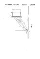
- FIG. 2 is a side view of the light collector shown in FIG. 1;
- FIG. 3 is a side view of a light collector similar to that shown in FIG. 1 showing further improvements;
- FIG. 4 is a side view of a light collector similar to that shown in FIG. 2 showing further improvements.
- FIG. 5 is a top view of a light collector similar to that shown in FIG. 2, illustrating a further improvement.
- the light collector includes a generally rectangular mirror box 10, having relatively wide top and bottom mirrors 12 and 14, and relatively narrow side mirrors 16 and 18. At one end of the mirror box are a row of photomultiplier tubes 20.
- the photomultiplier tubes 20 are provided with rectangular light receiving faces so that they can be efficiently stacked along the end of the mirror box.
- the open end of the mirror box opposite the photomultiplier tubes extends along the scan line 24 of a laser beam 26 that is deflected in the direction of arrow A to scan the photo-stimulable phosphor sheet 28.
- An elongated reflector 30 is positioned opposite the open end of the mirror box 10 to reflect emitted light into the mirror box.
- FIG. 2 is a cross-sectional view of the light collector shown in FIG. 1.
- some of the stimulating radiation from scanning beam 26, as indicated by rays 32 is reflected from the surface of the phosphor sheet 28 and enters the mirror box 10.
- Most of the stimulating radiation is absorbed by the filter 22, but some is reflected as indicated by phantom rays 34 back onto the surface of the photo-stimulable phosphor.
- These rays reflected off the surface of the filter 22 can be a cause of prestimulation in this light collector.
- the faces of the photomultiplier tube are arranged at an oblique angle with respect to the end of the mirror box as shown in FIG. 3.
- the rays 32 which directly reach the face of the infrared filter 22 are subject to multiple reflections (as shown by phantoms rays 34 in FIG. 3) on the return trip. Due to the multiple reflections, most of the energy in the rays is dissipated by the time they reach the phosphor sheet.
- the top and bottom mirrors 12 and 14 are angled with respect to each other so that the end of the mirror box near the photomultiplier tubes is wider than the end near the photo-stimulable phosphor sheet as shown in FIG. 4.
- the side mirrors 16 and 18 may be angled with respect to each other with their wide ends near the photodetectors, to further increase collection efficiency and reduce prestimulation.
- FIG. 5 is a top view of a light collector having angled side mirrors. As a result, a greater percentage of the emitted light reaches the photomultiplier tube with fewer reflections, and stimulating light that reaches the infrared filter 22 directly (as shown by rays 32 in FIG. 4) and is reflected from the surface of the infrared filter (as shown by phantom rays 34 in FIG. 4) is trapped.
- Prestimulation may be further reduced by providing a mask 36 as shown in FIG. 4 extending between the bottom edge of mirror 30 and the bottom mirror 14 of the mirror box.
- the mask 36 defines a slot 38 through which the scanning beam passes to the surface of the photo-stimulable phosphor 28, and which allows the emitted light to enter the collector.
- Prestimulation may be further reduced by applying an antireflection coating to the surface of filter 22.
- a light collector according to the present invention was constructed using diamond machined aluminum plates for the mirrors.
- the diamond machined mirror surfaces were 90% reflective for the emitted wavelength of 400 nm.
- the mirror box was 43 cm wide by 10 cm long.
- the height of the mirror box at the small end was 2.29 cm, and the height at the large end was adjustable.
- Five 4 ⁇ 8.8 cm rectangular faced photomultiplier tubes were mounted at the wide end of the mirror box with their faces perpendicular to the plane of the phosphor sheet and at an angle of 56° to the top adjustable mirror.
- An elliptical cross section reflector 30 was employed, having one focal point at the scan line and the other near the detector face. It is noted that the shape of reflector 30 is not critical and, other shapes such as circular cross sections could be employed.
- the light collector was used in a photo-stimulable phosphor imaging apparatus, and found to have high collection efficiency, low prestimulation and response that was readily made uniform across a scan line by adjusting the individual gains of the photomultiplier tubes.
- the mirrors were made of metal, optical glass plates with reflective coatings may also be used.
- the light collector according to the present invention is useful in photo-stimulable phosphor imaging apparatus used for example in x-radiography.
- the light collector has the advantages that it is easily constructed, has high light collection efficiency, low prestimulation, and uniform collection efficiency across a scan line.
Abstract
Description
Claims (10)
Priority Applications (5)
| Application Number | Priority Date | Filing Date | Title |
|---|---|---|---|
| US06/917,935 US4743758A (en) | 1986-10-14 | 1986-10-14 | Light collector for photo-stimulable phosphor imaging apparatus |
| DE8787907063T DE3778164D1 (en) | 1986-10-14 | 1987-10-05 | LIGHT COLLECTOR FOR A PHOTOSTIMULATABLE PHOSPHORIC IMAGE DETECTING DEVICE. |
| PCT/US1987/002532 WO1988002969A1 (en) | 1986-10-14 | 1987-10-05 | Light collector for photo-stimulable phosphor imaging apparatus |
| EP87907063A EP0330662B1 (en) | 1986-10-14 | 1987-10-05 | Light collector for photo-stimulable phosphor imaging apparatus |
| JP62506418A JPH02500232A (en) | 1986-10-14 | 1987-10-05 | Light collector for imaging devices with stimulated luminescent phosphors |
Applications Claiming Priority (1)
| Application Number | Priority Date | Filing Date | Title |
|---|---|---|---|
| US06/917,935 US4743758A (en) | 1986-10-14 | 1986-10-14 | Light collector for photo-stimulable phosphor imaging apparatus |
Publications (1)
| Publication Number | Publication Date |
|---|---|
| US4743758A true US4743758A (en) | 1988-05-10 |
Family
ID=25439532
Family Applications (1)
| Application Number | Title | Priority Date | Filing Date |
|---|---|---|---|
| US06/917,935 Expired - Lifetime US4743758A (en) | 1986-10-14 | 1986-10-14 | Light collector for photo-stimulable phosphor imaging apparatus |
Country Status (5)
| Country | Link |
|---|---|
| US (1) | US4743758A (en) |
| EP (1) | EP0330662B1 (en) |
| JP (1) | JPH02500232A (en) |
| DE (1) | DE3778164D1 (en) |
| WO (1) | WO1988002969A1 (en) |
Cited By (17)
| Publication number | Priority date | Publication date | Assignee | Title |
|---|---|---|---|---|
| US4827129A (en) * | 1987-02-17 | 1989-05-02 | Siemens Aktiengesellschaft | Sweep device for a storage luminescent screen |
| WO1991020156A1 (en) * | 1990-06-21 | 1991-12-26 | Eastman Kodak Company | Electrographic process utilizing fluorescent toner and filtered detector for generating an electrical image signal |
| US5105079A (en) * | 1990-12-21 | 1992-04-14 | Eastman Kodak Company | Split V-roof mirror collector having improved collection efficiency |
| US5125013A (en) * | 1991-08-08 | 1992-06-23 | Eastman Kodak Company | Method of scanning of toned image in a liquid gate |
| US5134290A (en) * | 1991-11-22 | 1992-07-28 | Eastman Kodak Company | Collector for storage phosphor imaging system |
| US5140160A (en) * | 1991-11-22 | 1992-08-18 | Eastman Kodak Company | Collector for storage phosphor imaging system |
| US5151592A (en) * | 1990-12-21 | 1992-09-29 | Eastman Kodak Company | Flare minimization in split v-roof mirror collector |
| US5218205A (en) * | 1991-05-14 | 1993-06-08 | Siemens Aktiengesellschaft | Read-out system for a luminescent storage screen |
| DE4329691A1 (en) * | 1992-09-03 | 1994-03-17 | Fujitsu Ltd | Scanner for an X=ray image stored on phosphorescent plate - having controllable system to ensure constant signal intensity from image regions of varying density |
| US5416336A (en) * | 1991-04-17 | 1995-05-16 | Orion-Yhtyma Oy | Light collector and read-out apparatus for stimulated radiation image |
| US5493128A (en) * | 1994-08-25 | 1996-02-20 | Eastman Kodak Company | Method and apparatus for indexing cassettes |
| US5506417A (en) * | 1994-11-21 | 1996-04-09 | Eastman Kodak Company | Light collector for photostimulable phosphor imaging systems |
| US5541421A (en) * | 1994-11-21 | 1996-07-30 | Eastman Kodak Company | Light collector having optically coated acrylic substrate |
| US6176364B1 (en) | 1997-10-11 | 2001-01-23 | Eastman Kodak Company | Device for simplified vertical loading of an X-ray cassette into a transport receptacle of a processing apparatus for X-ray cassettes |
| US6278126B2 (en) | 1997-10-11 | 2001-08-21 | Eastman Kodak Company | Transport device for X-ray cassettes, each having a phosphor sheet stimulable by X-rays, in a cassette processing apparatus |
| US20040159804A1 (en) * | 2003-02-13 | 2004-08-19 | Boutet John C. | Prism use for CR collector efficiency boost |
| US20050254052A1 (en) * | 2004-05-11 | 2005-11-17 | Urbon Michael P | Alignment of light collector to laser scanline |
Citations (6)
| Publication number | Priority date | Publication date | Assignee | Title |
|---|---|---|---|---|
| US31847A (en) * | 1861-03-26 | Jesse young | ||
| JPS5215216A (en) * | 1975-07-28 | 1977-02-04 | Canon Inc | Facsimile light receiving device |
| US4346295A (en) * | 1978-12-26 | 1982-08-24 | Fuji Photo Film Co., Ltd. | Radiation image read out device |
| EP0137674A1 (en) * | 1983-08-23 | 1985-04-17 | Fuji Photo Film Co., Ltd. | Radiation image read-out apparatus |
| US4616129A (en) * | 1983-12-01 | 1986-10-07 | Fuji Photo Film Co., Ltd. | Light detecting apparatus |
| US4680473A (en) * | 1984-03-09 | 1987-07-14 | Fuji Photo Film Co., Ltd. | Radiation image read-out apparatus including selective stimulating ray reflection preventing means |
Family Cites Families (3)
| Publication number | Priority date | Publication date | Assignee | Title |
|---|---|---|---|---|
| JPS60111634A (en) * | 1983-11-19 | 1985-06-18 | 富士写真フイルム株式会社 | Radiation image information reading apparatus |
| JPS6190570A (en) * | 1984-10-11 | 1986-05-08 | Fuji Photo Film Co Ltd | Reader or radiation image information |
| JPS61290857A (en) * | 1985-06-19 | 1986-12-20 | Fuji Photo Film Co Ltd | Reader for radiation picture image information |
-
1986
- 1986-10-14 US US06/917,935 patent/US4743758A/en not_active Expired - Lifetime
-
1987
- 1987-10-05 EP EP87907063A patent/EP0330662B1/en not_active Expired - Lifetime
- 1987-10-05 JP JP62506418A patent/JPH02500232A/en active Pending
- 1987-10-05 DE DE8787907063T patent/DE3778164D1/en not_active Expired - Fee Related
- 1987-10-05 WO PCT/US1987/002532 patent/WO1988002969A1/en active IP Right Grant
Patent Citations (6)
| Publication number | Priority date | Publication date | Assignee | Title |
|---|---|---|---|---|
| US31847A (en) * | 1861-03-26 | Jesse young | ||
| JPS5215216A (en) * | 1975-07-28 | 1977-02-04 | Canon Inc | Facsimile light receiving device |
| US4346295A (en) * | 1978-12-26 | 1982-08-24 | Fuji Photo Film Co., Ltd. | Radiation image read out device |
| EP0137674A1 (en) * | 1983-08-23 | 1985-04-17 | Fuji Photo Film Co., Ltd. | Radiation image read-out apparatus |
| US4616129A (en) * | 1983-12-01 | 1986-10-07 | Fuji Photo Film Co., Ltd. | Light detecting apparatus |
| US4680473A (en) * | 1984-03-09 | 1987-07-14 | Fuji Photo Film Co., Ltd. | Radiation image read-out apparatus including selective stimulating ray reflection preventing means |
Non-Patent Citations (4)
| Title |
|---|
| Dmetro Andrychuk, "A Multi-Image Optical System," Applied Optics, vol. 3, No. 8 (Aug. 1964), pp. 933-938. |
| Dmetro Andrychuk, A Multi-Image Optical System, Applied Optics, vol. 3, No. 8 (Aug. 1964), pp. 933 938. * |
| Gerald F. Marshall, "Tapered Light Guide Condenser: a Design Approach," Guided Wave Optical Systems & Devices II, Proc. SPIE, vol. 176, pp. 161-217 (1979). |
| Gerald F. Marshall, Tapered Light Guide Condenser: a Design Approach, Guided Wave Optical Systems & Devices II, Proc. SPIE, vol. 176, pp. 161 217 (1979). * |
Cited By (22)
| Publication number | Priority date | Publication date | Assignee | Title |
|---|---|---|---|---|
| US4827129A (en) * | 1987-02-17 | 1989-05-02 | Siemens Aktiengesellschaft | Sweep device for a storage luminescent screen |
| US5105451A (en) * | 1988-12-07 | 1992-04-14 | Eastman Kodak Company | Electrographic process utilizing fluorescent toner and filtered detector for generating an electrical image signal |
| WO1991020156A1 (en) * | 1990-06-21 | 1991-12-26 | Eastman Kodak Company | Electrographic process utilizing fluorescent toner and filtered detector for generating an electrical image signal |
| US5105079A (en) * | 1990-12-21 | 1992-04-14 | Eastman Kodak Company | Split V-roof mirror collector having improved collection efficiency |
| US5151592A (en) * | 1990-12-21 | 1992-09-29 | Eastman Kodak Company | Flare minimization in split v-roof mirror collector |
| US5416336A (en) * | 1991-04-17 | 1995-05-16 | Orion-Yhtyma Oy | Light collector and read-out apparatus for stimulated radiation image |
| US5218205A (en) * | 1991-05-14 | 1993-06-08 | Siemens Aktiengesellschaft | Read-out system for a luminescent storage screen |
| US5125013A (en) * | 1991-08-08 | 1992-06-23 | Eastman Kodak Company | Method of scanning of toned image in a liquid gate |
| US5134290A (en) * | 1991-11-22 | 1992-07-28 | Eastman Kodak Company | Collector for storage phosphor imaging system |
| US5140160A (en) * | 1991-11-22 | 1992-08-18 | Eastman Kodak Company | Collector for storage phosphor imaging system |
| DE4329691A1 (en) * | 1992-09-03 | 1994-03-17 | Fujitsu Ltd | Scanner for an X=ray image stored on phosphorescent plate - having controllable system to ensure constant signal intensity from image regions of varying density |
| US5493128A (en) * | 1994-08-25 | 1996-02-20 | Eastman Kodak Company | Method and apparatus for indexing cassettes |
| EP0698813A1 (en) | 1994-08-25 | 1996-02-28 | Eastman Kodak Company | Method and apparatus for indexing cassettes |
| US5541421A (en) * | 1994-11-21 | 1996-07-30 | Eastman Kodak Company | Light collector having optically coated acrylic substrate |
| EP0715315A2 (en) * | 1994-11-21 | 1996-06-05 | Eastman Kodak Company | Light collector for photostimulable phosphor imaging systems |
| US5506417A (en) * | 1994-11-21 | 1996-04-09 | Eastman Kodak Company | Light collector for photostimulable phosphor imaging systems |
| EP0715315A3 (en) * | 1994-11-21 | 1998-02-04 | Eastman Kodak Company | Light collector for photostimulable phosphor imaging systems |
| US6176364B1 (en) | 1997-10-11 | 2001-01-23 | Eastman Kodak Company | Device for simplified vertical loading of an X-ray cassette into a transport receptacle of a processing apparatus for X-ray cassettes |
| US6278126B2 (en) | 1997-10-11 | 2001-08-21 | Eastman Kodak Company | Transport device for X-ray cassettes, each having a phosphor sheet stimulable by X-rays, in a cassette processing apparatus |
| US20040159804A1 (en) * | 2003-02-13 | 2004-08-19 | Boutet John C. | Prism use for CR collector efficiency boost |
| US20050254052A1 (en) * | 2004-05-11 | 2005-11-17 | Urbon Michael P | Alignment of light collector to laser scanline |
| US7167245B2 (en) | 2004-05-11 | 2007-01-23 | Eastman Kodak Company | Alignment of light collector to laser scanline |
Also Published As
| Publication number | Publication date |
|---|---|
| EP0330662A1 (en) | 1989-09-06 |
| EP0330662B1 (en) | 1992-04-08 |
| WO1988002969A1 (en) | 1988-04-21 |
| DE3778164D1 (en) | 1992-05-14 |
| JPH02500232A (en) | 1990-01-25 |
Similar Documents
| Publication | Publication Date | Title |
|---|---|---|
| US4742225A (en) | Elliptical cylinder light collector for photosimulable phosphor imaging apparatus | |
| US4743758A (en) | Light collector for photo-stimulable phosphor imaging apparatus | |
| US4743759A (en) | Light collector for photo-stimulable phosphor imaging system | |
| EP0516781B1 (en) | Flare minimization in split v-roof mirror collector | |
| US5105079A (en) | Split V-roof mirror collector having improved collection efficiency | |
| US4775791A (en) | Transparent sheet light collector for photostimulable phosphor imaging | |
| US5140160A (en) | Collector for storage phosphor imaging system | |
| US5107116A (en) | Split V-roof mirror collector for photostimulable phosphor imaging system | |
| US5134290A (en) | Collector for storage phosphor imaging system | |
| US6621094B2 (en) | Radiation image read-out method and apparatus | |
| US20020024030A1 (en) | Radiation image read-out method and apparatus | |
| JP2571116B2 (en) | Radiation image information reader | |
| US6797977B2 (en) | Radiation image read-out method and apparatus | |
| JP2593232B2 (en) | Radiation image information reader | |
| US20040159804A1 (en) | Prism use for CR collector efficiency boost | |
| US20050109964A1 (en) | Integrated scan module for a computer radiography input scanning system | |
| JPH0556491B2 (en) | ||
| JPH0310283B2 (en) | ||
| JPS61162036A (en) | Radiation picture information reader |
Legal Events
| Date | Code | Title | Description |
|---|---|---|---|
| FEPP | Fee payment procedure |
Free format text: PAYOR NUMBER ASSIGNED (ORIGINAL EVENT CODE: ASPN); ENTITY STATUS OF PATENT OWNER: LARGE ENTITY |
|
| AS | Assignment |
Owner name: EASTMAN KODAK COMPANY, ROCHESTER, NEW YORK A NJ CO Free format text: ASSIGNMENT OF ASSIGNORS INTEREST.;ASSIGNORS:CHAN, YALI E.;BOUTET, JOHN C.;KULPINSKI, ROBERT W.;AND OTHERS;REEL/FRAME:004832/0055;SIGNING DATES FROM 19860916 TO 19870923 |
|
| STCF | Information on status: patent grant |
Free format text: PATENTED CASE |
|
| FPAY | Fee payment |
Year of fee payment: 4 |
|
| FPAY | Fee payment |
Year of fee payment: 8 |
|
| FEPP | Fee payment procedure |
Free format text: PAYER NUMBER DE-ASSIGNED (ORIGINAL EVENT CODE: RMPN); ENTITY STATUS OF PATENT OWNER: LARGE ENTITY Free format text: PAYOR NUMBER ASSIGNED (ORIGINAL EVENT CODE: ASPN); ENTITY STATUS OF PATENT OWNER: LARGE ENTITY |
|
| FPAY | Fee payment |
Year of fee payment: 12 |
|
| AS | Assignment |
Owner name: CREDIT SUISSE, CAYMAN ISLANDS BRANCH, AS ADMINISTR Free format text: FIRST LIEN OF INTELLECTUAL PROPERTY SECURITY AGREEMENT;ASSIGNOR:CARESTREAM HEALTH, INC.;REEL/FRAME:019649/0454 Effective date: 20070430 Owner name: CREDIT SUISSE, CAYMAN ISLANDS BRANCH, AS ADMINISTR Free format text: SECOND LIEN INTELLECTUAL PROPERTY SECURITY AGREEME;ASSIGNOR:CARESTREAM HEALTH, INC.;REEL/FRAME:019773/0319 Effective date: 20070430 |
|
| AS | Assignment |
Owner name: CARESTREAM HEALTH, INC., NEW YORK Free format text: RELEASE OF SECURITY INTEREST IN INTELLECTUAL PROPERTY (FIRST LIEN);ASSIGNOR:CREDIT SUISSE AG, CAYMAN ISLANDS BRANCH;REEL/FRAME:026069/0012 Effective date: 20110225 |