US4732440A - Self resonant scanning device - Google Patents
Self resonant scanning device Download PDFInfo
- Publication number
- US4732440A US4732440A US06/790,134 US79013485A US4732440A US 4732440 A US4732440 A US 4732440A US 79013485 A US79013485 A US 79013485A US 4732440 A US4732440 A US 4732440A
- Authority
- US
- United States
- Prior art keywords
- springs
- mirror
- attachment
- spring
- scanner
- Prior art date
- Legal status (The legal status is an assumption and is not a legal conclusion. Google has not performed a legal analysis and makes no representation as to the accuracy of the status listed.)
- Expired - Fee Related
Links
Images


Classifications
-
- G—PHYSICS
- G02—OPTICS
- G02B—OPTICAL ELEMENTS, SYSTEMS OR APPARATUS
- G02B7/00—Mountings, adjusting means, or light-tight connections, for optical elements
- G02B7/18—Mountings, adjusting means, or light-tight connections, for optical elements for prisms; for mirrors
- G02B7/182—Mountings, adjusting means, or light-tight connections, for optical elements for prisms; for mirrors for mirrors
- G02B7/1821—Mountings, adjusting means, or light-tight connections, for optical elements for prisms; for mirrors for mirrors for rotating or oscillating mirrors
Definitions
- This invention referrs to self resonant scanning devices often used in laser scanning equipment.
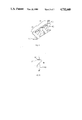
- FIG. 1 shows a S-flex shaped spring (2) with a rolled circular segment at the top (1) and a flat attachment tab complete with a hole for attachment by a rivet (3) at the bottom.
- the center of gyration of the S-flex member is indicated by (4).
- FIG. 2 shows a pair of the S-flex springs with the rolled cylinder segment for pin attachment at the top and the bottom (1A) with the center of gyration of the S-Flex springs (2A) indicated by the axis (4A).
- FIG. 3 Shows the steps in the assembly of the S-flex unit from the spring blank an FIG. 3A where each leg or projection (5) from the central connecting member (6) is a flattened spring and the combination of the two opposing projections becomes a flat opposed S-flex (7).
- the first leg of the spring assembly is formed by doubly bending the projecting part (8).
- the second part of the S-flex is formed by doubly bending the other projecting leg of the opposed pair (9) connected by a common portion of the central connecting member (6).
- FIG. 4 shows the fully formed part with two opposed pairs of the S-flex structure (7D) attached at the base by a common connecting member (6D).
- the flat connecting tabs with a rivet hole (3D) are now aligned at the top of the spring elements (2D) and the axis of gyration runs through (4D).
- FIG. 5 shows a side view of a S-flex unit with the spring effective length shown by a dotted line (10).
- the attachment tabs (3E) contribute to the spring length up to the point of attachment which is the rivet hole (11) while a short distance beyond the hole (12) does not participate in the spring length.
- the axis of gyration runs through point (4E).
- FIG. 6 shows a mirror attachment base unit with 4 rivet holes arrayed to match the holes in the flat tabs of the S-flex (13), the holes are in an attachment central member (14).
- the central member has a projecting cross member (15) at right angles and centrally located along the central member.
- the iron pins (16) are located at the ends of the cross member where they project and the pins are magnitized.
- FIG. 7 shows the combination of the S-Flex spring assembly shown in FIG. 4 with the mirror attachment base shown in FIG. 6.
- the mirror attachment consists of the central member (14G) attached to the tabs (3G) in the S-flex spring assembly by rivets (17).
- the cross member of the mirror attachment (15G) is arranged with the iron pins (16G) pointed towards the base of the S-flex connecting member.
- the S-flex unit consisting of two sets of opposed S-flex springs (7H) with the common central connecting member at the bottom (6G).
- the axis of gyration of the entire assembly is an axis through point (4G) parellel to the base commecting member.
- FIG. 8 shows the array of S-flex springs as shown in FIG. 4 made of individually formed springs without the connecting member.
- FIG. 9 shows the assembly in FIG. 7 mounted on a base (18) by means of rivets (19). There is a core pin of iron (20) used for mounting the driving coil.
- FIG. 10 shows the assembled scanner with a mirror (21) attached to the mirror attachment base as shown in FIG. 9 (14J, 15J) and coils (22) added which interact with the pins (16J) and are mounted on a base (18J).
- FIG. 11 shows a side view of the S-flex spring with the parts identified as used in the calculations in the text of the patant.
- FIG. 12 shows the mirror with key dimensions used in calculations identified.
- the mirror is Dm long, Lm wide and has a thickness of Hm.
- FIG. 13 shows the mirror attachment base as in FIG. 6 with the calculation dimensions indicated.
- scanners are becoming ever more important with the high speed printers, optical storage devices, and bar code readers all using a scanning device in conjunction with a beam of electromagnetic radiation to transform electronic signals between computer memories and printed copy and visa versa.
- the scanners are required to scan a beam of light by moving a mirror to illuminate a small discrete portion of a document or to pulse light along a defined path. This controlled motion of a mirror surface has become a major element in modern computerized data systems.
- Typical uses of the scanners has also expanded into phototype setting, printing, laser cameras, resistor trimming, computer output microfilming, laser scanning microscopes microchip lithographics and the list of uses is steadily growing.
- Mirror devices are used for scanning where beams of electromagnetic radiation are deflected in a predetermined manner by excitation of the mirror in various planes. This allows a narrow beam to be deflected to cover a wide arc. Large deflection angles and very rapid deflection speed are critical to the effective use of the devices which employ the scanners as is the accuracy of the scan. It is the combination of these three atributes that define the technical limits to many processes.
- deflectors for large deflection angles and high resonant angles are sensitive to machine and external vibrations. These devices employ torsion bars and flexural members, leaf springs or bearings.
- Torsion bar scanner designs consist of a thin rod which in the basic design is held at one end and has a mirror attached at the other end.
- the drive motor excites the mirror to move in a resonant manner by twisting the rod, typically through electromagnetic coupling.
- Several improvements to these designs have been made with the torsion rod clamped at both ends and the mirror centrally located on the free length of the torsion rod. Further improvements resulted from the tensile loading of the torsion rod in the direction of the length of the rod.
- This device maintains a high wobble (cross axis displacement) that is independent of the frequency.
- the unit has wobble of 5 to 10 microradians in the best units and can be as high as 20 microradians.
- the unit has a place in ultra high frequency applications (over 1,000 hertz and more frequently 3,000 to 4,000 hertz). Since the deflector must move freely the pivot points must be lightly restrained, in some cases bearings are used but this provides minor improvements. Bearings may be used to improve accuracy in the rod and other devices but where ever bearings are used wear of the bearings becomes a problem. In these high resolution scans the placement or accuracy of the beam is critical since any deviation causes errors in the output. The errors would prevent good reproduction of the original in the case of a printer or would cause errors due to inexact alignment of the scanned areas. The cross axis error causes the beam of a laser which is being deflected by the scanner mirror to wander.
- Taut band scanners consist of a rectangular band of material streched between two points. Mirror and drive are attached to the taut band and the deflection of the band deflects the centrally mounted mirror. This type scanner is useful for wide deflection anglse with 30 degree deflections possible.
- the main problem is ponderous speeds at the high deflections with 10 to 24 hertz ranges representing the available technology.
- the angle of deflection is restricted drastically with 2 degrees (Mechanical) typical limits on a 600 to 800 hertx scanner design.
- the cross axis wobble of these scanners also is typically 10 microradians.
- bearings are another way to support an oscillating member and could be used to form a scanner.
- the basic problem is the balls need some freedom of motion to roll and the result is a scanner with a 50 microradian cross axis wobble.
- An additional reason precluding the use of bearings as scanners is that the ball bearing supports have limited bearing life due to the rapid sliding of the balls in bearing races at high resonant frequencies.
- the travel of the bearings is also limited in many cases to a back and forth motion by the rapid oscillation of the scanner which again adds to the wear problem.
- Bearings are used to stabilize some scanners deflection but the result is not as good as the cross flexures and the life limitation severely limits the commercial use of the bearing stabilized deflectors. These problems are much worse as the resonant frequency of the scanner is increased.
- Cross flex members have been used in some scanner applications such as the ISX from General Scanning Inc, a Massachusetts company.
- the construction used consists of straight spring elements clamped at the top and the bottom.
- the attachment means adds inertia and since the spring is straight the attachment is at a maximum distance thus the radius of gyration is high.
- the high inertia cuts the resonant frequency for a given scanner configuration. When the high inertia is unbalanced it causes shaking forces to be applied to the scanner.
- the General Scanner models use thickness variations within the straight sections to enhance the strength of the springs at the clamp points where the metal is thickest and then reduce the metal thickness to as little as 50% of the thickness at the clamping point.
- the straight springs tend to transmit incident vibrations easily to the scanner.
- the problems with the straight cross flex scanners result in a practical limit of the resonant frequency to around 250 hertz as a result of the height of the unit increasing as the length of the spring increases.
- the result of this is that the mass of the mirror, mirror support and the drive are multiplied times the square of the radius of gyration in determining the moment of inertia so at the higher resonant frequencies which would indicate longer springs, a point of diminishing returns is rapidly reached.
- the cross flex member concept is attractive due to the higher stability of the deflectors to the cross axis wobble for wide angle scanners even under external vibrations.
- the limits of frequency are however troublesome.
- the spring length is determined by the endurance limit stress allowed in the material. While better materials are one solution, this type of improvement is limited and unlikely to be achived without a major materials breakthrough.
- the longer lenths of a given spring material have a lower stress for a given deflection. Countering the lowered stress is the higher inertia of the oscillating member since the radius of gyration is increased. This radius of gyration, defined as the square root of the term (moment of inertia divided by mass), is critical since increases cut the resonant frequency and thus the performance of the scanner. A breakthrough to provide a longer length with low inertial properties was needed.
- a system of opposing S-flex shapes where the spring is bent in one or more places has been invented to provide a longer spring length with a low inertia that is needed to obtain resonant scanners that have larger deflection angles at higher frequencies.
- the S-flex springs have a radius of gyration that is minimized by the forming of the spring into an S or Z shape. While an inverted L shape would also work, the single bend halves the advantage of the lenghtening of the spring and the non symetrical shape causes uneven stress distributions and motion.
- the curved or flat sections between the top and bottom is part of the spring length up to the point of attachment and since this length participates in the flexure, the flexural length is greatly expanded. The expanded length reduces the stress on the spring at a given deflection and the reduction is obtained without increasing the radius of gyration of the oscillating member.
- the S-flex configuration by lending itself to the low inertia attachment of a deflector mirror to the base permits higher resonant frequencies of the scanner.
- a single S-flex spring while it accomplishes many of the improvements noted still is deficient in that the radius of gyration is twice the height of the radius of gyration of the opposing s-flex system, this height being the distance from the axis of rotation to the center of gravity of the mirror.
- the radius of gyration is the axis of the points where the opposed springs cross each other.
- a plurality of the S-flex springs arrayed in opposition resolves the deficiencies seen in the single spring. This also gives a high degree of cross axis placement accuracy and nearly eliminates sensitivity to external vibrations.
- the S shaped springs placed in opposition act like a torsion spring. Placing them in opposition provides lower radius of gyration. By opposing them a discrete structure is formed which provides added stiffness in the cross axis direction, The s-flex curve allows much higher resonant frequencies from cross flexural type designs.
- a second problem that plagues the scanner industry is the attachment of the deflecting device to the spring menbers.
- the s-flex unlike other forms of the oscillating members, lends itself to the attachment at both top and bottom.
- the top of the S shape is a tab which may be attached to the mirror base in a variety of ways. Rivets, spot welds, screws or a variety of other attachment means are easily installed without weakening the part. Adhesives have considerable area of contact which makes these light weight attachments possible. In a like manner the large base area can be attached with rivets, or any other fastening method.
- pins can be employed by further forming a cylindrical tube at the end of the S or Z shape. In this tubular attachment is fitted a pin that attaches the spring member to the base or the mirror. This type of attachment can be employed to squeeze a little more length out of a flexure in cases where the space is limited.
- An additional advantage of the curved springs is a lower value of the factor usually designated as q.
- This number q which is a measure of the sharpness of the resonant curve of the scanner is important since a sharp curve requires higher accuracy in the drive circuits since small drive deviations cause large drops in the motion of the scanning mirror.
- the S-flex opposed curved springs have been tested at half the q value of an equilivent scanner employing straight springs.
- a performance index is used to quantify the performance of the several types of flexures and pivoting devices on the market and to show the differences between these devices in a way that is meaningful to a user of scanning devices.
- the performance index is defined as the degree of angular deflection times the resonant frequency divided by the cross axis deflection, a single number is developed for any system that weighs the key factors in the unit performance.
- the angular optical deflection of the scanner is a measure of the amount that can be seen in a given set of conditions. A scanner with twice the deflection would examine twice the area with each scan if the distsnces between the scanner and the target were the same.
- Resonant deflection is listed in the formula as theta ( ⁇ ) and is measured in degrees of deflection peak to peak.
- the frequency (F) of the unit is measured at the resonant point and expressed in hertz, cycles per second. Higher frequencies could cover more area or could cover the same area in more detail.
- the cross axis deflection which is sometimes called wobble is an indicator of the quality of the unit with the smaller cross axis wobble giving an indication that the scan would more nearly cover the exact same area in each scan.
- the cross axis deflection is expressed in arc seconds and in the formula is represented by D.
- the performance index is thus ( ⁇ F)/D. It is illustrative to show the performance indices of some of the existing scanning units now in the marketplace. The numbers are presented in the following table:
- the URS series is much better than the IPC type with cantilevered springs they are in the same price range reflecting greater cost effectiveness of the bent spring technology.
- the other direct comparison is the 100 hertz ISX with the 100 hertz URS. While the performance index is the same, the ISX is much more expensive due to the elaborate and expensive clamping devices involved in the construction of the ISX.
- the calculations for the S-flex scanner are shown in a step by step manner for each element of the scanning unit.
- a major advantage of this invention is related to the ease of making the S-flex springs. With this type of spring it is relatively easy to change the parameters of the flexure to customize a unit for many specialized uses. With these basic calculations the resonant frequency can be varied by modifications in the spring, by changing the mass of the mirror or the mirror support or by adding mass in the form of the iron driving pins.
- the spring can be made from different materials, it can be wider or longer--the process of designing a scanner that is readily manufacturable is within the control of the designer and there are a wide range of possible changes to give the designer freedoms not previously possible with fixed purchased flexures. ##EQU1##
- the S-flex spring was designed for a 625 Hertz resonant frequency with a angular displacement of 40 degrees peak to peak (called the optical displacement as opposed to the mechanical displacement that is 1/2 of the optical displacement).
- the calculations in the preceeding section are employed to determine an optimum configuration. Many different exchanges can be made between the weights of the mirror or the mirror attachment, the length and the materials of the spring and other stated variables. The optimization usually takes into prime consideration the available mirrors and the easily made spring blanks.
- the mirror support used is a production item that is made from aluminum in a cross shape.
- the arms of the cross are 2.71 inches long in the direction parallel to the axis of the rotation (Lmm) and 1.0 inches in the direction at right angles to that axis (Wm).
- the mirror support is 0.062 inches thick aluminum.
- the magnetic pins are 0.047 inches radius (Rm) and 0.25 inches long (W1mm).
- the manufacture of the scanner starts with the S-flex spring configuration.
- the preferred material for the spring is Carpenter Custom 455 steel as made by Carpenter Steel Co of Reading, PA. This steel is fully described in U.S. Pat. No. 3,408,178 and is selected for its very high endurance limit and its toughness.
- the spring blank as shown in the Drawings is made by electrochemical machining where the unwanted metal is etched away. This machining method results in a smooth edged blank which prevents any stress rising points and it is easy to include holes or other means to attach the S-flex to the base and the mirror support however the spring blanks. In this embodiment there are 4 holes along the connecting member and one hole machined in the tip of each spring member. The spring blank could also be punched from strip stock.
- the spring is bent into the S shape manually with the help of a small jig to ensure a consistent shape or can be mass produced in future runs by bending dies.
- the spring element is annealed to remove all residual stresses.
- the spring is solution ammealed by heating to 1500 degrees F then it is water quenched.
- the formed spring now is stress free and in the correct shape.
- the spring is then hardened by a precipitation hardening treatment which requires the spring be brought to a temperature of 900 degrees F and held at that temperature for one half hour. Upon removal from the furnace the hardened spring is air cooled.
- the process literature by Carpenter Steel permits the hardening process to range from 900 to 1050 degrees F but best results are achived in a range of 900 to 925 degrees F.
- the steel of the S-Flex has a modulus of elasticity of 29,500,000 psi and an endurance limit of at least 110,000 psi as formed and hardened.
- the other parts of the unit are machined or cast.
- the mirror attachment member is machined by conventional means from aluminum sheet.
- a type 3003-H14 aluminum is preferred due to the excellent strength.
- the part is made as shown in the drawings with 4 holes matching the spring holes in spacing on the spring attachment member while the cross member is fitted with two rod shape pins that are highly magnetized. These pins are pressed into the aluminum with a small hand press.
- the base unit is cast aluminum of tye A356 aluminum alloy and is currently made by the lost wax method commonly used in manufacture of gold and silver ornaments. This part will eventually be die cast as the tooling is completed.
- the base has the holes for attachment of the connecting S-flex spring members in the base and for mounting the wire coils.
- the spring is then attached to the base with four rivets.
- the spring is then attached to the mirror attachment member with four rivets. These rivets are countersunk into the mirror attachment member to insure a smooth flat top to the unit where the mirror will be attached.
- Aluminum rivets are used for ease of handling, because they are light and to simplify the calculations since the holes can then be ignored in the calculations.
- the mirror attachment is by means of an Epoxy polymeric glue that has high strength but is flexible.
- the epoxy must not cause distortion in the mirror for the optical quality of the mirror is such that any stress applied to the backing of the mirror can cause major errors in the mirror flatness.
- the mirror is selected from front reflecting high optical quality mirrors such as those made from quartz glass with aluminum front surface coated with SiO2. Other reflective surfaces can be used to get high reflectivity for different wavelengths of radiation. Normally the mirror is optically flat to within one half wavelength although there are applications that require greater flatness. Great care is taken at this point to insure no slippage of the mirror that would unbalance the unit.
- the assembly of the spring and the mirror is complete but there is no driver in the scanner.
- Two small coils are added, one to power the unit by the interaction of a high frequency variation in a magnetic field made by the energizing of the coil and the subsequent interaction between the coil and the magnetic pins at the ends of the cross member of the mirror attachment part.
- These coils are made by winding fine wire on plastic bobbins.
- the coils are pressed onto a soft iron pin which projects from the back of the base to which it is attached by a press fit and where the projection into the coils is no less than 1/3 of the coil height and no more than 2/3 of the coil height.
- the iron pin serves to enhance the effect of the magnetic field.
- the second coil is identical to the first but, unlike the first coil which in use is energized to drive the scanner, it is not energized but is used to generate a current which is monitored by the driving electronics to provide a drive correction signal.
- the mounting of the second coil is similar to the mounting of the first coil.
- the testing and adjusting proceedure is critical to the unit performance.
- the unit is attached to calibrated drive electronics and finr adjustment is made by changing the inertia of the moving member (the mirror, support, and the drive pins). This is done by addition or removal of small amounts of weights.
- a second adjustment emoplys the bending of tabs to add or to detract from the distance from the center of rotation of the weight of the tabs.
Abstract
Description
______________________________________
                                      PER-
Deflection
        Frequency Cross               FORM-
angle (Θ)
        in Hertz  axis      Manufacturer
                                      ANCE
in degrees
        (F)       deflection
                            & model   INDEX
______________________________________
30      3000      5         Gen Scanning
                                      18,000
30      3937      5         Gen Scanning
                                      23,622
                            Model IFX
 40#    250       0.5       Gen Scanning
                                      20,000
                            Model ISX
30*     100       10        Gen Scanning
                                        300
                            Model
                            IPC 1510
30*     100       0.5       Gen Scanning
                                       6,000
30*     100       0.5       Laser Scanning
                                       6,000
                            Products Inc
                            URS 100
 40#    625       0.5       Laser Scanning
                                      50,000
                            URS 625
______________________________________
 *these units are direct replacements
 # these units represent the limits of cross flexure designs
Claims (25)
Priority Applications (1)
| Application Number | Priority Date | Filing Date | Title |
|---|---|---|---|
| US06/790,134 US4732440A (en) | 1985-10-22 | 1985-10-22 | Self resonant scanning device |
Applications Claiming Priority (1)
| Application Number | Priority Date | Filing Date | Title |
|---|---|---|---|
| US06/790,134 US4732440A (en) | 1985-10-22 | 1985-10-22 | Self resonant scanning device |
Publications (1)
| Publication Number | Publication Date |
|---|---|
| US4732440A true US4732440A (en) | 1988-03-22 |
Family
ID=25149740
Family Applications (1)
| Application Number | Title | Priority Date | Filing Date |
|---|---|---|---|
| US06/790,134 Expired - Fee Related US4732440A (en) | 1985-10-22 | 1985-10-22 | Self resonant scanning device |
Country Status (1)
| Country | Link |
|---|---|
| US (1) | US4732440A (en) |
Cited By (70)
| Publication number | Priority date | Publication date | Assignee | Title |
|---|---|---|---|---|
| US4861125A (en) * | 1988-05-06 | 1989-08-29 | Tencor Instruments | Suspension assembly for a scanning mirror |
| US4902083A (en) * | 1988-05-31 | 1990-02-20 | Reflection Technology, Inc. | Low vibration resonant scanning unit for miniature optical display apparatus |
| US5003300A (en) * | 1987-07-27 | 1991-03-26 | Reflection Technology, Inc. | Head mounted display for miniature video display system |
| US5015831A (en) * | 1988-11-07 | 1991-05-14 | Photographic Sciences Corporation | Scan modules for bar code readers and the like in which scan elements are flexurally supported |
| US5023905A (en) * | 1988-07-25 | 1991-06-11 | Reflection Technology, Inc. | Pocket data receiver with full page visual display |
| US5048077A (en) * | 1988-07-25 | 1991-09-10 | Reflection Technology, Inc. | Telephone handset with full-page visual display |
| US5099110A (en) * | 1989-10-30 | 1992-03-24 | Symbol Technologies, Inc. | Power saving scanning arrangement |
| US5115120A (en) * | 1990-06-26 | 1992-05-19 | Photographic Sciences Corporation | Scan modules for bar code readers and in which scan elements are flexurally supported |
| US5168149A (en) * | 1989-10-30 | 1992-12-01 | Symbol Technologies, Inc. | Scan pattern generators for bar code symbol readers |
| US5172261A (en) * | 1990-11-01 | 1992-12-15 | Toyota Jidosha Kabushiki Kaisha | Oscillatory mirror device with two exciting means |
| EP0523413A2 (en) * | 1991-06-28 | 1993-01-20 | Eastman Kodak Company | Beam scanning galvanometer with spring supported mirror |
| US5206492A (en) * | 1989-10-30 | 1993-04-27 | Symbol Technologies, Inc. | Bar code symbol scanner with reduced power usage to effect reading |
| US5245463A (en) * | 1990-08-07 | 1993-09-14 | Omron Corporation | Optical scanner |
| US5245464A (en) * | 1988-08-12 | 1993-09-14 | Laser Scan Vision Aps | Deflecting instrument, controllable reflecting device herefor and use hereof |
| US5262627A (en) * | 1989-10-30 | 1993-11-16 | Symbol Technologies, Inc. | Scanning arrangement and method |
| US5277076A (en) * | 1992-06-08 | 1994-01-11 | Ball Corporation | Reactionless scan mechanism |
| US5280165A (en) * | 1989-10-30 | 1994-01-18 | Symbol Technolgoies, Inc. | Scan pattern generators for bar code symbol readers |
| US5329103A (en) * | 1991-10-30 | 1994-07-12 | Spectra-Physics | Laser beam scanner with low cost ditherer mechanism |
| US5367151A (en) * | 1989-10-30 | 1994-11-22 | Symbol Technologies, Inc. | Slim scan module with interchangeable scan element |
| US5373148A (en) * | 1989-10-30 | 1994-12-13 | Symbol Technologies, Inc. | Optical scanners with scan motion damping and orientation of astigmantic laser generator to optimize reading of two-dimensionally coded indicia |
| US5412198A (en) * | 1989-10-30 | 1995-05-02 | Symbol Technologies, Inc. | High-speed scanning arrangement with high-frequency, low-stress scan element |
| US5477043A (en) * | 1989-10-30 | 1995-12-19 | Symbol Technologies, Inc. | Scanning arrangement for the implementation of scanning patterns over indicia by driving the scanning elements in different component directions |
| US5479000A (en) * | 1989-10-30 | 1995-12-26 | Symbol Technologies, Inc. | Compact scanning module for reading bar codes |
| US5486944A (en) * | 1989-10-30 | 1996-01-23 | Symbol Technologies, Inc. | Scanner module for symbol scanning system |
| US5514861A (en) * | 1988-05-11 | 1996-05-07 | Symbol Technologies, Inc. | Computer and/or scanner system mounted on a glove |
| WO1996013746A1 (en) * | 1994-10-26 | 1996-05-09 | Board Of Regents Of The University Of Washington | Miniature optical scanner for a two axis scanning system |
| US5525764A (en) * | 1994-06-09 | 1996-06-11 | Junkins; John L. | Laser scanning graphic input system |
| US5528411A (en) * | 1993-05-03 | 1996-06-18 | General Scanning Inc. | Resonant scanner |
| US5529277A (en) * | 1994-09-20 | 1996-06-25 | Ball Corporation | Suspension system having two degrees of rotational freedom |
| US5543610A (en) * | 1989-10-30 | 1996-08-06 | Symbol Technologies, Inc. | Compact bar code scanning arrangement |
| US5550669A (en) * | 1993-04-19 | 1996-08-27 | Martin Marietta Corporation | Flexure design for a fast steering scanning mirror |
| US5552592A (en) * | 1989-10-30 | 1996-09-03 | Symbol Technologies, Inc. | Slim scan module with dual detectors |
| US5583331A (en) * | 1989-10-30 | 1996-12-10 | Symbol Technologies, Inc. | Arrangement for compensating for scan line curvature |
| US5614706A (en) * | 1992-05-15 | 1997-03-25 | Symbol Technologies, Inc. | Bar code scanning assembly with cantilevered or torsionally vibrating flexural member |
| US5621371A (en) * | 1989-10-30 | 1997-04-15 | Symbol Technologies, Inc. | Arrangement for two-dimensional optical scanning with springs of different moduli of elasticity |
| US5629790A (en) * | 1993-10-18 | 1997-05-13 | Neukermans; Armand P. | Micromachined torsional scanner |
| US5708262A (en) * | 1992-05-15 | 1998-01-13 | Symbol Technologies, Inc. | Miniature high speed scan element mounted on a personal computer interface card |
| US5828051A (en) * | 1991-02-12 | 1998-10-27 | Omron Corporation | Optical scanner and bar code reader employing same |
| US5831780A (en) * | 1996-01-31 | 1998-11-03 | Raytheon Company | Continually supported thin mirror with force-type actuators |
| US5861549A (en) * | 1996-12-10 | 1999-01-19 | Xros, Inc. | Integrated Silicon profilometer and AFM head |
| US5895866A (en) * | 1996-01-22 | 1999-04-20 | Neukermans; Armand P. | Micromachined silicon micro-flow meter |
| US5914801A (en) * | 1996-09-27 | 1999-06-22 | Mcnc | Microelectromechanical devices including rotating plates and related methods |
| US5917176A (en) * | 1996-09-17 | 1999-06-29 | Datalogic S.P.A. | Optical code hand-reader |
| US6036098A (en) * | 1992-05-15 | 2000-03-14 | Symbol Technologies, Inc. | Miniature scan element operably connected to a personal computer interface card |
| US6044705A (en) * | 1993-10-18 | 2000-04-04 | Xros, Inc. | Micromachined members coupled for relative rotation by torsion bars |
| US6275319B1 (en) | 1999-07-20 | 2001-08-14 | Lasesys Corporation | High scan efficiency galvanometric laser scanning device |
| US6392220B1 (en) | 1998-09-02 | 2002-05-21 | Xros, Inc. | Micromachined members coupled for relative rotation by hinges |
| US6396620B1 (en) | 2000-10-30 | 2002-05-28 | Mcnc | Electrostatically actuated electromagnetic radiation shutter |
| US6404727B1 (en) | 1997-11-12 | 2002-06-11 | Iolon, Inc. | Electromagnetic rotary actuator |
| US6467345B1 (en) | 1993-10-18 | 2002-10-22 | Xros, Inc. | Method of operating micromachined members coupled for relative rotation |
| US6586738B2 (en) | 2001-04-13 | 2003-07-01 | Mcnc | Electromagnetic radiation detectors having a micromachined electrostatic chopper device |
| US6616042B1 (en) * | 1989-10-30 | 2003-09-09 | Symbol Technologies, Inc. | Clamp assembly for detachably clamping spring in electro-optical system for reading indicia |
| US6637657B2 (en) | 2001-04-06 | 2003-10-28 | Symbol Technologies, Inc. | Compact scan module with magnetically centered scan mirror |
| US20040046123A1 (en) * | 2001-04-13 | 2004-03-11 | Mcnc Research And Development Institute | Electromagnetic radiation detectors having a microelectromechanical shutter device |
| US20050046979A1 (en) * | 2003-06-24 | 2005-03-03 | Dave Hiley | Precision mirror displacement assembly |
| US20060044655A1 (en) * | 2004-08-30 | 2006-03-02 | Fischer Paul F | Laser cutting system |
| US20060290774A1 (en) * | 2005-06-24 | 2006-12-28 | Carl Wittenberg | Arrangement for, and a method of, reducing image distortion due to electrical interference |
| US20070103756A1 (en) * | 2005-11-08 | 2007-05-10 | Poco Graphite, Inc. | System, method, and apparatus for conversion bonding of precursor subcomponents into a unitary monolith |
| US20070150778A1 (en) * | 2005-12-09 | 2007-06-28 | Asml Netherlands B.V. | Lithographic apparatus and device manufacturing method |
| US20070206252A1 (en) * | 2006-03-06 | 2007-09-06 | Inphase Technologies, Inc. | Miniature flexure based scanners for angle multiplexing |
| US20070291333A1 (en) * | 2006-06-15 | 2007-12-20 | Canon Kabushiki Kaisha | Image reading apparatus and reflecting mirror unit |
| US20080013097A1 (en) * | 2006-06-23 | 2008-01-17 | Asml Holding N.V. | Resonant scanning mirror |
| US20080030826A1 (en) * | 2006-08-03 | 2008-02-07 | Inphase Technologies, Inc. | Miniature single actuator scanner for angle multiplexing with circularizing and pitch correction capability |
| US7388699B1 (en) | 2005-07-11 | 2008-06-17 | Coffee Curtis L | Musical laser display device |
| US20140268383A1 (en) * | 2013-03-15 | 2014-09-18 | Raytheon Company | Reaction compensated tilt platform |
| US9052511B1 (en) | 2012-08-10 | 2015-06-09 | Jeffrey Knirck | Method and apparatus for resonant rotational oscillator |
| US10203475B2 (en) | 2016-10-20 | 2019-02-12 | Raytheon Company | Curved magnetic actuators, and systems, and methods for mounting tilt platforms |
| US10634871B2 (en) * | 2016-12-27 | 2020-04-28 | Xi'an Jiaotong University | Low-profile dual-axis deflection device having deflection axes intersecting at mirror surface and method for achieving dual-axila deflection |
| FR3102901A1 (en) | 2019-11-05 | 2021-05-07 | Tu-Yang | Electromechanical resonator with shifted secondary resonance modes. |
| US11555983B2 (en) * | 2020-02-20 | 2023-01-17 | Hitachi-Lg Data Storage, Inc. | Light source module |
Citations (5)
| Publication number | Priority date | Publication date | Assignee | Title |
|---|---|---|---|---|
| GB489543A (en) * | 1937-01-25 | 1938-07-25 | Ig Farbenindustrie Ag | Improvements in electromagnetic apparatus for controlling beams of light |
| US3519336A (en) * | 1966-11-10 | 1970-07-07 | Eng Automotive Sciences Inc | Rearview mirror adaptor for angling the mirror by remote control |
| US3532408A (en) * | 1968-05-20 | 1970-10-06 | Bulova Watch Co Inc | Resonant torsional oscillators |
| US3612642A (en) * | 1969-06-27 | 1971-10-12 | Bulova Watch Co Inc | A high-velocity optical scanner including a torsional fork supporting two reflectors |
| US4421381A (en) * | 1980-04-04 | 1983-12-20 | Yokogawa Hokushin Electric Corp. | Mechanical vibrating element |
-
1985
- 1985-10-22 US US06/790,134 patent/US4732440A/en not_active Expired - Fee Related
Patent Citations (5)
| Publication number | Priority date | Publication date | Assignee | Title |
|---|---|---|---|---|
| GB489543A (en) * | 1937-01-25 | 1938-07-25 | Ig Farbenindustrie Ag | Improvements in electromagnetic apparatus for controlling beams of light |
| US3519336A (en) * | 1966-11-10 | 1970-07-07 | Eng Automotive Sciences Inc | Rearview mirror adaptor for angling the mirror by remote control |
| US3532408A (en) * | 1968-05-20 | 1970-10-06 | Bulova Watch Co Inc | Resonant torsional oscillators |
| US3612642A (en) * | 1969-06-27 | 1971-10-12 | Bulova Watch Co Inc | A high-velocity optical scanner including a torsional fork supporting two reflectors |
| US4421381A (en) * | 1980-04-04 | 1983-12-20 | Yokogawa Hokushin Electric Corp. | Mechanical vibrating element |
Cited By (109)
| Publication number | Priority date | Publication date | Assignee | Title |
|---|---|---|---|---|
| US5003300A (en) * | 1987-07-27 | 1991-03-26 | Reflection Technology, Inc. | Head mounted display for miniature video display system |
| US4861125A (en) * | 1988-05-06 | 1989-08-29 | Tencor Instruments | Suspension assembly for a scanning mirror |
| US5514861A (en) * | 1988-05-11 | 1996-05-07 | Symbol Technologies, Inc. | Computer and/or scanner system mounted on a glove |
| US4902083A (en) * | 1988-05-31 | 1990-02-20 | Reflection Technology, Inc. | Low vibration resonant scanning unit for miniature optical display apparatus |
| AU618783B2 (en) * | 1988-05-31 | 1992-01-09 | Reflection Technology, Inc. | Low vibration resonant scanning unit for miniature optical display apparatus |
| US5023905A (en) * | 1988-07-25 | 1991-06-11 | Reflection Technology, Inc. | Pocket data receiver with full page visual display |
| US5048077A (en) * | 1988-07-25 | 1991-09-10 | Reflection Technology, Inc. | Telephone handset with full-page visual display |
| US5245464A (en) * | 1988-08-12 | 1993-09-14 | Laser Scan Vision Aps | Deflecting instrument, controllable reflecting device herefor and use hereof |
| US5015831A (en) * | 1988-11-07 | 1991-05-14 | Photographic Sciences Corporation | Scan modules for bar code readers and the like in which scan elements are flexurally supported |
| US5479000A (en) * | 1989-10-30 | 1995-12-26 | Symbol Technologies, Inc. | Compact scanning module for reading bar codes |
| US5477043A (en) * | 1989-10-30 | 1995-12-19 | Symbol Technologies, Inc. | Scanning arrangement for the implementation of scanning patterns over indicia by driving the scanning elements in different component directions |
| US5621371A (en) * | 1989-10-30 | 1997-04-15 | Symbol Technologies, Inc. | Arrangement for two-dimensional optical scanning with springs of different moduli of elasticity |
| US5206492A (en) * | 1989-10-30 | 1993-04-27 | Symbol Technologies, Inc. | Bar code symbol scanner with reduced power usage to effect reading |
| US5583331A (en) * | 1989-10-30 | 1996-12-10 | Symbol Technologies, Inc. | Arrangement for compensating for scan line curvature |
| US5168149A (en) * | 1989-10-30 | 1992-12-01 | Symbol Technologies, Inc. | Scan pattern generators for bar code symbol readers |
| US5262627A (en) * | 1989-10-30 | 1993-11-16 | Symbol Technologies, Inc. | Scanning arrangement and method |
| US5581070A (en) * | 1989-10-30 | 1996-12-03 | Symbol Technologies, Inc. | Omni-directional scan pattern generator in electro-optical scanners |
| US5825013A (en) * | 1989-10-30 | 1998-10-20 | Symbol Technologies, Inc. | Electromagnetically activated scanner with suspended scanner component |
| US5280165A (en) * | 1989-10-30 | 1994-01-18 | Symbol Technolgoies, Inc. | Scan pattern generators for bar code symbol readers |
| US5281801A (en) * | 1989-10-30 | 1994-01-25 | Symbol Technologies, Inc. | Low-cost low-power scanner and method |
| US5552592A (en) * | 1989-10-30 | 1996-09-03 | Symbol Technologies, Inc. | Slim scan module with dual detectors |
| US5367151A (en) * | 1989-10-30 | 1994-11-22 | Symbol Technologies, Inc. | Slim scan module with interchangeable scan element |
| US5373148A (en) * | 1989-10-30 | 1994-12-13 | Symbol Technologies, Inc. | Optical scanners with scan motion damping and orientation of astigmantic laser generator to optimize reading of two-dimensionally coded indicia |
| US5543610A (en) * | 1989-10-30 | 1996-08-06 | Symbol Technologies, Inc. | Compact bar code scanning arrangement |
| US5412198A (en) * | 1989-10-30 | 1995-05-02 | Symbol Technologies, Inc. | High-speed scanning arrangement with high-frequency, low-stress scan element |
| US6616042B1 (en) * | 1989-10-30 | 2003-09-09 | Symbol Technologies, Inc. | Clamp assembly for detachably clamping spring in electro-optical system for reading indicia |
| US5486944A (en) * | 1989-10-30 | 1996-01-23 | Symbol Technologies, Inc. | Scanner module for symbol scanning system |
| US5099110A (en) * | 1989-10-30 | 1992-03-24 | Symbol Technologies, Inc. | Power saving scanning arrangement |
| US5481099A (en) * | 1989-10-30 | 1996-01-02 | Symbol Technologies, Inc. | Scanning arrangement for the implementation of omni-directional scanning patterns over indicia |
| US5115120A (en) * | 1990-06-26 | 1992-05-19 | Photographic Sciences Corporation | Scan modules for bar code readers and in which scan elements are flexurally supported |
| US5444565A (en) * | 1990-08-07 | 1995-08-22 | Omron Corporation | Optical scanner |
| US5245463A (en) * | 1990-08-07 | 1993-09-14 | Omron Corporation | Optical scanner |
| US5172261A (en) * | 1990-11-01 | 1992-12-15 | Toyota Jidosha Kabushiki Kaisha | Oscillatory mirror device with two exciting means |
| US5828051A (en) * | 1991-02-12 | 1998-10-27 | Omron Corporation | Optical scanner and bar code reader employing same |
| EP0523413A3 (en) * | 1991-06-28 | 1995-03-08 | Eastman Kodak Co | Beam scanning galvanometer with spring supported mirror |
| US5280377A (en) * | 1991-06-28 | 1994-01-18 | Eastman Kodak Company | Beam scanning galvanometer with spring supported mirror |
| EP0523413A2 (en) * | 1991-06-28 | 1993-01-20 | Eastman Kodak Company | Beam scanning galvanometer with spring supported mirror |
| US5329103A (en) * | 1991-10-30 | 1994-07-12 | Spectra-Physics | Laser beam scanner with low cost ditherer mechanism |
| US5708262A (en) * | 1992-05-15 | 1998-01-13 | Symbol Technologies, Inc. | Miniature high speed scan element mounted on a personal computer interface card |
| US5614706A (en) * | 1992-05-15 | 1997-03-25 | Symbol Technologies, Inc. | Bar code scanning assembly with cantilevered or torsionally vibrating flexural member |
| US6036098A (en) * | 1992-05-15 | 2000-03-14 | Symbol Technologies, Inc. | Miniature scan element operably connected to a personal computer interface card |
| US5277076A (en) * | 1992-06-08 | 1994-01-11 | Ball Corporation | Reactionless scan mechanism |
| US5550669A (en) * | 1993-04-19 | 1996-08-27 | Martin Marietta Corporation | Flexure design for a fast steering scanning mirror |
| US5528411A (en) * | 1993-05-03 | 1996-06-18 | General Scanning Inc. | Resonant scanner |
| US5629790A (en) * | 1993-10-18 | 1997-05-13 | Neukermans; Armand P. | Micromachined torsional scanner |
| US6467345B1 (en) | 1993-10-18 | 2002-10-22 | Xros, Inc. | Method of operating micromachined members coupled for relative rotation |
| US6044705A (en) * | 1993-10-18 | 2000-04-04 | Xros, Inc. | Micromachined members coupled for relative rotation by torsion bars |
| US5525764A (en) * | 1994-06-09 | 1996-06-11 | Junkins; John L. | Laser scanning graphic input system |
| US5529277A (en) * | 1994-09-20 | 1996-06-25 | Ball Corporation | Suspension system having two degrees of rotational freedom |
| US5557444A (en) * | 1994-10-26 | 1996-09-17 | University Of Washington | Miniature optical scanner for a two axis scanning system |
| WO1996013746A1 (en) * | 1994-10-26 | 1996-05-09 | Board Of Regents Of The University Of Washington | Miniature optical scanner for a two axis scanning system |
| US6272907B1 (en) | 1995-12-11 | 2001-08-14 | Xros, Inc. | Integrated silicon profilometer and AFM head |
| US5895866A (en) * | 1996-01-22 | 1999-04-20 | Neukermans; Armand P. | Micromachined silicon micro-flow meter |
| US5831780A (en) * | 1996-01-31 | 1998-11-03 | Raytheon Company | Continually supported thin mirror with force-type actuators |
| US5917176A (en) * | 1996-09-17 | 1999-06-29 | Datalogic S.P.A. | Optical code hand-reader |
| US6087747A (en) * | 1996-09-27 | 2000-07-11 | Mcnc | Microelectromechanical beam for allowing a plate to rotate in relation to a frame in a microelectromechanical device |
| US6134042A (en) * | 1996-09-27 | 2000-10-17 | Mcnc | Reflective mems actuator with a laser |
| US5914801A (en) * | 1996-09-27 | 1999-06-22 | Mcnc | Microelectromechanical devices including rotating plates and related methods |
| US6555201B1 (en) | 1996-09-27 | 2003-04-29 | Mcnc | Method for fabricating a microelectromechanical bearing |
| US6256134B1 (en) | 1996-09-27 | 2001-07-03 | Mcnc | Microelectromechanical devices including rotating plates and related methods |
| US5861549A (en) * | 1996-12-10 | 1999-01-19 | Xros, Inc. | Integrated Silicon profilometer and AFM head |
| US6404727B1 (en) | 1997-11-12 | 2002-06-11 | Iolon, Inc. | Electromagnetic rotary actuator |
| US6392220B1 (en) | 1998-09-02 | 2002-05-21 | Xros, Inc. | Micromachined members coupled for relative rotation by hinges |
| US6275319B1 (en) | 1999-07-20 | 2001-08-14 | Lasesys Corporation | High scan efficiency galvanometric laser scanning device |
| US6304359B1 (en) | 1999-07-20 | 2001-10-16 | Lasesys Corporation | High scan efficiency galvanometric laser scanning device |
| US6396620B1 (en) | 2000-10-30 | 2002-05-28 | Mcnc | Electrostatically actuated electromagnetic radiation shutter |
| US6637657B2 (en) | 2001-04-06 | 2003-10-28 | Symbol Technologies, Inc. | Compact scan module with magnetically centered scan mirror |
| US7026602B2 (en) | 2001-04-13 | 2006-04-11 | Research Triangle Institute | Electromagnetic radiation detectors having a microelectromechanical shutter device |
| US20040046123A1 (en) * | 2001-04-13 | 2004-03-11 | Mcnc Research And Development Institute | Electromagnetic radiation detectors having a microelectromechanical shutter device |
| US6586738B2 (en) | 2001-04-13 | 2003-07-01 | Mcnc | Electromagnetic radiation detectors having a micromachined electrostatic chopper device |
| US20050046979A1 (en) * | 2003-06-24 | 2005-03-03 | Dave Hiley | Precision mirror displacement assembly |
| US6972885B2 (en) | 2003-06-24 | 2005-12-06 | Drs Sensors & Targeting Systems, Inc. | Precision mirror displacement assembly |
| US20060044655A1 (en) * | 2004-08-30 | 2006-03-02 | Fischer Paul F | Laser cutting system |
| US7233424B2 (en) | 2004-08-30 | 2007-06-19 | Dot Intellectual Properties, Llc | Steering assembly with electromagnetic actuators |
| US7307650B2 (en) * | 2005-06-24 | 2007-12-11 | Symbol Technologies, Inc. | Arrangement for, and a method of, reducing image distortion due to electrical interference |
| WO2007001681A3 (en) * | 2005-06-24 | 2009-04-30 | Symbol Technologies Inc | An arrangement for, and a method of, reducing image distortion due to electrical interference |
| US20060290774A1 (en) * | 2005-06-24 | 2006-12-28 | Carl Wittenberg | Arrangement for, and a method of, reducing image distortion due to electrical interference |
| WO2007001681A2 (en) * | 2005-06-24 | 2007-01-04 | Symbol Technologies, Inc. | An arrangement for, and a method of, reducing image distortion due to electrical interference |
| US7388699B1 (en) | 2005-07-11 | 2008-06-17 | Coffee Curtis L | Musical laser display device |
| US7931853B2 (en) | 2005-11-08 | 2011-04-26 | Poco Graphite, Inc. | System, method, and apparatus for conversion bonding of precursor subcomponents into a unitary monolith |
| US20080069754A1 (en) * | 2005-11-08 | 2008-03-20 | Poco Graphite, Inc. | System, Method, and Apparatus for Conversion Bonding of Precursor Subcomponents Into a Unitary Monolith |
| US20070103756A1 (en) * | 2005-11-08 | 2007-05-10 | Poco Graphite, Inc. | System, method, and apparatus for conversion bonding of precursor subcomponents into a unitary monolith |
| US20070162781A1 (en) * | 2005-12-09 | 2007-07-12 | Asml Netherlands B.V. | Lithographic apparatus and device manufacturing method |
| US20070150779A1 (en) * | 2005-12-09 | 2007-06-28 | Asml Netherlands B.V. | Lithographic apparatus and device manufacturing method |
| US20070150778A1 (en) * | 2005-12-09 | 2007-06-28 | Asml Netherlands B.V. | Lithographic apparatus and device manufacturing method |
| US7714305B2 (en) | 2005-12-09 | 2010-05-11 | Asml Holding N.V. | Lithographic apparatus and device manufacturing method |
| US7626181B2 (en) | 2005-12-09 | 2009-12-01 | Asml Netherlands B.V. | Lithographic apparatus and device manufacturing method |
| US20070206252A1 (en) * | 2006-03-06 | 2007-09-06 | Inphase Technologies, Inc. | Miniature flexure based scanners for angle multiplexing |
| US7336409B2 (en) | 2006-03-06 | 2008-02-26 | Inphase Technologies, Inc. | Miniature flexure based scanners for angle multiplexing |
| US20070291333A1 (en) * | 2006-06-15 | 2007-12-20 | Canon Kabushiki Kaisha | Image reading apparatus and reflecting mirror unit |
| US9554010B2 (en) * | 2006-06-15 | 2017-01-24 | Canon Kabushiki Kaisha | Image reading apparatus and reflecting mirror unit |
| US20080013097A1 (en) * | 2006-06-23 | 2008-01-17 | Asml Holding N.V. | Resonant scanning mirror |
| US7697115B2 (en) * | 2006-06-23 | 2010-04-13 | Asml Holding N.V. | Resonant scanning mirror |
| US20080192318A1 (en) * | 2006-08-03 | 2008-08-14 | Inphase Technologies, Inc. | Miniature single actuator scanner for angle multiplexing with circularizing and pitch correction capability |
| US20080197263A1 (en) * | 2006-08-03 | 2008-08-21 | Inphase Technologies, Inc. | Miniature single actuator scanner for angle multiplexing with circularizing and pitch correction capability |
| US7405853B2 (en) | 2006-08-03 | 2008-07-29 | Inphase Technologies, Inc. | Miniature single actuator scanner for angle multiplexing with circularizing and pitch correction capability |
| US7551336B2 (en) | 2006-08-03 | 2009-06-23 | Inphase Technologies, Inc. | Miniature single actuator scanner for angle multiplexing with circularizing and pitch correction capability |
| US20080192317A1 (en) * | 2006-08-03 | 2008-08-14 | Inphase Technologies, Inc. | Miniature single actuator scanner for angle multiplexing with circularizing and pitch correction capability |
| US7453618B2 (en) | 2006-08-03 | 2008-11-18 | Inphase Technologies, Inc. | Miniature single actuator scanner for angle multiplexing with circularizing and pitch correction capability |
| US20080030826A1 (en) * | 2006-08-03 | 2008-02-07 | Inphase Technologies, Inc. | Miniature single actuator scanner for angle multiplexing with circularizing and pitch correction capability |
| US9052511B1 (en) | 2012-08-10 | 2015-06-09 | Jeffrey Knirck | Method and apparatus for resonant rotational oscillator |
| US9304314B1 (en) | 2012-08-10 | 2016-04-05 | Jeffrey Knirck | Method and apparatus for resonant rotational oscillator |
| US9658427B2 (en) * | 2013-03-15 | 2017-05-23 | Raytheon Company | Reaction compensated tilt platform |
| US20140268383A1 (en) * | 2013-03-15 | 2014-09-18 | Raytheon Company | Reaction compensated tilt platform |
| US10203475B2 (en) | 2016-10-20 | 2019-02-12 | Raytheon Company | Curved magnetic actuators, and systems, and methods for mounting tilt platforms |
| US10634871B2 (en) * | 2016-12-27 | 2020-04-28 | Xi'an Jiaotong University | Low-profile dual-axis deflection device having deflection axes intersecting at mirror surface and method for achieving dual-axila deflection |
| FR3102901A1 (en) | 2019-11-05 | 2021-05-07 | Tu-Yang | Electromechanical resonator with shifted secondary resonance modes. |
| EP3819695A1 (en) | 2019-11-05 | 2021-05-12 | Tu-Yang | Electromechanical resonator with offset secondary resonance modes |
| US11555983B2 (en) * | 2020-02-20 | 2023-01-17 | Hitachi-Lg Data Storage, Inc. | Light source module |
Similar Documents
| Publication | Publication Date | Title |
|---|---|---|
| US4732440A (en) | Self resonant scanning device | |
| US5280377A (en) | Beam scanning galvanometer with spring supported mirror | |
| US9024992B2 (en) | Vibrating element, optical scanning device, and image forming device and image projection device using same | |
| US7388702B2 (en) | Micro-oscillating member, light-deflector, and image-forming apparatus | |
| EP0520388B1 (en) | Magnetic position sensor | |
| CN100514116C (en) | Optical deflector and optical instrument using the same | |
| US3601476A (en) | Adjustable optical device | |
| WO1984003823A1 (en) | A pivotal mechanism upon which tracking mirrors and the like used in optical systems may be mounted | |
| US5221933A (en) | Beam scanning galvanometer with low inertia mirror and magnet | |
| US20050121522A1 (en) | Inertial drive scanning arrangement and method | |
| WO2006025888A1 (en) | Laser cutting system | |
| JPH06167669A (en) | Integrated galvanometer scanning device | |
| JPH1020226A (en) | Optical scanner | |
| US3932809A (en) | Deflector galvanometer | |
| CN101784938A (en) | Oscillating body apparatus and manufacturing method thereof, optical deflector and image forming apparatus | |
| JP4407046B2 (en) | Optical scanner | |
| JP5296424B2 (en) | Optical scanning device, image forming device, display device, and input device | |
| JP3787877B2 (en) | Optical scanning device | |
| JP2979666B2 (en) | Scale equipment | |
| JP2534111B2 (en) | Vibration support mechanism | |
| US4662464A (en) | Load detecting mechanism | |
| JPH053057B2 (en) | ||
| EP0442442A1 (en) | Objective lens actuator for optical storage drive | |
| Ono | Optical beam deflector using a piezoelectric bimorph actuator | |
| JPH0534616A (en) | Plane scanning optical device |
Legal Events
| Date | Code | Title | Description |
|---|---|---|---|
| AS | Assignment |
Owner name: LASESYS CORPORATION, CALIFORNIA Free format text: ASSIGNMENT OF ASSIGNORS INTEREST.;ASSIGNOR:GADHOK, JAGMOHAN S.;REEL/FRAME:005206/0942 Effective date: 19891220 |
|
| REMI | Maintenance fee reminder mailed | ||
| LAPS | Lapse for failure to pay maintenance fees | ||
| FP | Lapsed due to failure to pay maintenance fee |
Effective date: 19920322 |
|
| FEPP | Fee payment procedure |
Free format text: PETITION RELATED TO MAINTENANCE FEES FILED (ORIGINAL EVENT CODE: PMFP); ENTITY STATUS OF PATENT OWNER: SMALL ENTITY |
|
| FEPP | Fee payment procedure |
Free format text: PETITION RELATED TO MAINTENANCE FEES FILED (ORIGINAL EVENT CODE: PMFP); ENTITY STATUS OF PATENT OWNER: SMALL ENTITY |
|
| FEPP | Fee payment procedure |
Free format text: PETITION RELATED TO MAINTENANCE FEES DENIED/DISMISSED (ORIGINAL EVENT CODE: PMFD); ENTITY STATUS OF PATENT OWNER: SMALL ENTITY |
|
| SULP | Surcharge for late payment | ||
| SULP | Surcharge for late payment | ||
| PRDP | Patent reinstated due to the acceptance of a late maintenance fee |
Effective date: 19950825 |
|
| FEPP | Fee payment procedure |
Free format text: PETITION RELATED TO MAINTENANCE FEES DENIED/DISMISSED (ORIGINAL EVENT CODE: PMFD); ENTITY STATUS OF PATENT OWNER: SMALL ENTITY |
|
| PRDP | Patent reinstated due to the acceptance of a late maintenance fee |
Effective date: 19960503 |
|
| LAPS | Lapse for failure to pay maintenance fees |
Free format text: PATENT EXPIRED FOR FAILURE TO PAY MAINTENANCE FEES (ORIGINAL EVENT CODE: EXP.) |
|
| STCH | Information on status: patent discontinuation |
Free format text: PATENT EXPIRED DUE TO NONPAYMENT OF MAINTENANCE FEES UNDER 37 CFR 1.362 |