US4729629A - Bonded sheath cable with lubricant over seam - Google Patents
Bonded sheath cable with lubricant over seam Download PDFInfo
- Publication number
- US4729629A US4729629A US07/019,071 US1907187A US4729629A US 4729629 A US4729629 A US 4729629A US 1907187 A US1907187 A US 1907187A US 4729629 A US4729629 A US 4729629A
- Authority
- US
- United States
- Prior art keywords
- bonded
- cable according
- sheath cable
- layer
- bonded sheath
- Prior art date
- Legal status (The legal status is an assumption and is not a legal conclusion. Google has not performed a legal analysis and makes no representation as to the accuracy of the status listed.)
- Expired - Lifetime
Links
Images


Classifications
-
- G—PHYSICS
- G02—OPTICS
- G02B—OPTICAL ELEMENTS, SYSTEMS OR APPARATUS
- G02B6/00—Light guides; Structural details of arrangements comprising light guides and other optical elements, e.g. couplings
- G02B6/44—Mechanical structures for providing tensile strength and external protection for fibres, e.g. optical transmission cables
- G02B6/4401—Optical cables
- G02B6/4415—Cables for special applications
- G02B6/4416—Heterogeneous cables
-
- G—PHYSICS
- G02—OPTICS
- G02B—OPTICAL ELEMENTS, SYSTEMS OR APPARATUS
- G02B6/00—Light guides; Structural details of arrangements comprising light guides and other optical elements, e.g. couplings
- G02B6/44—Mechanical structures for providing tensile strength and external protection for fibres, e.g. optical transmission cables
- G02B6/4401—Optical cables
- G02B6/4407—Optical cables with internal fluted support member
-
- G—PHYSICS
- G02—OPTICS
- G02B—OPTICAL ELEMENTS, SYSTEMS OR APPARATUS
- G02B6/00—Light guides; Structural details of arrangements comprising light guides and other optical elements, e.g. couplings
- G02B6/44—Mechanical structures for providing tensile strength and external protection for fibres, e.g. optical transmission cables
- G02B6/4401—Optical cables
- G02B6/4429—Means specially adapted for strengthening or protecting the cables
- G02B6/443—Protective covering
Definitions
- This invention relates to a bonded sheath cable, and more particularly to a cable having a metallic sheath wrapped around a cable core so as to form a longitudinal seam and wherein the metallic shield is bonded to a plastic outer jacket.
- U.S. Pat. No. 3,137,120 discloses the use of a thermoplastic resin tape over the overlapping edge of the metal sheath and securing it in place with two helically wound binding strands. A film of oil is applied to the underside of the tape to assure that all portions adhere to the metallic sheath.
- U.S. Pat. No. 3,943,271 teaches the use of a bridging tape along the metallic shield overlap seam in combination with a filling compound applied over and under the metallic shield. The bridging tape serves to prevent the outer edge of the lap seam from cutting into the outer jacket and freely moves when the copper cable expands, and the flooding compound serves to prevent moisture intrusion.
- U.S. Pat. No. 4,075,419 teaches a seam cable wherein an elastomeric and resilient element is provided as a bridge over the metal shield overlap in order to solve the problem of expansion of high voltage conventional power cables due to an increase in temperature which can cause the metal shield overlap to cut into the plastic outside jacket. Excessive stretching of the outer plastic jacket is eliminated by decoupling the plastic jacket from the metal tape overlap using a resilient bridging element. Also of interest, U.S. Pat. No.
- 4,221,926 discloses a waterproof shielded cable construction process which includes applying a heat-shrinkable tape over the metallic shield overlap seam either with or without a water blocking material present in the interstices therebetween in order to prevent ripping of the cable at the overlap seam due to severe bending incurred during cable installation.
- the bonded sheath cable comprises a cable either of the conventional electrical conductor type or of the newer optical fiber type.
- a layer of plastic surrounds and encloses the cable, and a metallic sheath is wrapped around the plastic layer so as to form a longitudinally extending overlapped seam having overlying and underlying edge portions which are bonded together in a suitable fashion including use of an applied adhesive or heat sealing of the overlapped edge portions together if the metallic shield has been provided with a suitable copolymer coating for corrosion protection and the like.
- a layer of jelly-like lubricating material is applied along the length of the longitudinal seam in order to prevent bonding of the overlapped metallic shield seam with the plastic jacket which is applied to and surrounds the metallic shield.
- the plastic jacket is fully bonded to the metallic shield except where it overlies the jelly-like lubricant which has been applied to the overlap seam area.
- the outside plastic jacket of the bonded sheath cable has been decoupled from the metallic shield overlap seam and this has been found to eliminate splitting of the plastic jacket adjacent the overlap if the bond between the overlapping edge portions is broken when twisting forces are applied to the cable.
- an improved bonded sheath cable which is better adapted to resist twisting and bending forces and lends itself to increased manufacturing speed due to the simplicity of its construction.
- the enhanced twisting strength of the cable is particularly advantageous since during underground installation a bonded sheath cable is subjected simultaneously to torsion, bending and twisting forces as it is pulled from an underground pathway and coiled into a "FIG. 8" configuration on the ground prior to being forced through another segment of the underground pathway.
- a bonded sheath cable incorporating a metallic shield with overlapping ends forming a longitudinal seam wherein the plastic jacket layer overlaying the metallic shield is decoupled therefrom at the overlapping seam area in order to provide enhanced resistance to twisting forces.
- Another object of the present invention is to provide a bonded sheath optical fiber cable of the type having a metallic shield wherein the overlapping edge portions thereof form a longitudinally extending seam and which is decoupled from the overlying plastic jacket by the provision of a jelly-like lubricant therebetween in order to eliminate jacket splitting due to twisting forces.
- Still another object of the present invention is to provide a bonded sheath cable of either the conventional electrical conductor or optical fiber type which is of a relatively simple improved construction so as to facilitate enhanced manufacturing speed and the attendant manufacturing economies associated therewith.
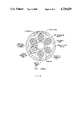
- FIG. 1 is a transverse cross-sectional view of a bonded sheath cable made in accordance with the present invention with the seam area enlarged for clarity of illustration;
- FIG. 2 is diagrammatic, exploded view showing a jelly-like lubricant extending across a metallic shield lap seam and positioned between the metallic shield and the plastic jacket layer of the bonded sheath cable;
- FIG. 3 is perspective view of a bonded sheath cable made in accordance with the present invention, with different parts broken away along the length of the cable for clarity of illustration;
- FIG. 4 is a transverse cross-sectional view of one type of bonded sheath cable made in accordance with the present invention and utilized to obtain the test results set forth herein.
- Cable 10 comprises a cable core 12 which may consist of any conventional electrical or optical fiber communications cable having one or more electrical conductors or light transmitting waveguides, respectively.
- cable core 12 comprises an optical fiber communications cable of the type having a central strength member and a plurality of buffer tubes positioned therearound wherein each tube contains a plurality of optical fiber light transmitting waveguides.
- plastic material 14 such as polyethylene, which is normally extruded onto cable core 12 during the manufacturing process. Also shown in the drawings (FIGS.
- Water blocking material 15 is an optional layer of water blocking material 15 applied over plastic layer 14 which can be provided at the request of a cable customer to serve as a water block or barrier.
- Water blocking material 15 may be a petroleum or silicone based jelly, a non-woven longitudinal tape and binder therefore or other suitable water barrier as may be appropriate.
- Metallic shield 16, which is most suitable a corrugated steel tape, is wrapped around plastic layer 14 and flooding material 15 so that the longitudinal edges thereof overlap so as to have overlying and underlying edge portions 16a, 16b, respectively, which form a longitudinally extending seam 16c (see FIG. 3) along the length of the cable.
- Metallic shield 16 serves as an armored steel jacket in order to protect cable 10 from compressive and impact forces as well as from such exogenous factors as gopher attacks when it is used in outdoor applications.
- the amount of overlap provided by edge portions 16a, 16b of metallic shield 16 may be of a width between about 5-15 millimeters in most cable constructions.
- Metallic shield or steel tape 16 may be of substantially any suitable thickness and may be coated, as a matter of choice, on one or both sides with a thin layer of a copolymer material (such as ethylene acrylic acid) to assist in preventing corrosion. If steel tape 16 is coated and the coating is provided on only one side, the copolymer material should be provided on the top surface of steel tape 16 to facilitate bonding with a jacket layer of plastic material 18 (most suitably polyethylene) which is applied over steel tape 16 during manufacture.
- a copolymer material such as ethylene acrylic acid
- edge portions 16a, 16b of steel tape 16 are bonded together in any conventionally suitable manner.
- overlying edge portion 16a can be secured to underlying edge portion 16b by heat sealing the overlap together.
- the overlapping edge portions can be secured together merely by applying a glue material 17 (see FIG. 2) between overlying edge portion 16a and underlying edge portion 16b.
- lubricant material 20 extends no greater than 80 percent of the width of the overlap of overlying and underlying edge portions 16a, 16b, respectively, in each direction from seam 16c.
- Lubricant material 20 is most suitably a petroleum based or silicone based jelly, although other lubricants may be used so long as the lubricant is compatible with plastic jacket layer 18.
- Lubricant material 20 most suitably is applied during the manufacturing process after steel tape 16 has been wrapped around plastic layer 14 and either prior to or simultaneously with the extrusion of plastic jacket layer 18 over steel tape 16.
- Lubricant material 20 is applied over seam 16c (or the longitudinal edge of edge portion 16a) and somewhat laterally to each side thereof to a width which should not exceed about 1/3 the total circumference of steel tape 16. Since applicant's cable requires less emphasis on achieving a perfect bond between edge portions 16a, 16b in the manufacturing process in order to prevent tearing of plastic jacket layer 18, manufacturing of the improved bonded sheath cable 10 is simplified and therefore manufacturing productivity is enhanced.
- edge portions 16a, 16b Even if the bond between edge portions 16a, 16b should be broken, the edge of overlying portion 16a, will be able to move relative to plastic jacket 18 due to lubricant 20 thereover and will not tend to "notch" or tear jacket 18 during twisting of cable 10.
- the performance characteristics of a bonded sheath cable made in accordance with the invention are set forth below in table form.
- the cable comprises an optical fiber cable core with a 30 fiber count contained in five stranded units each containing six tight buffered fibers stranded around a 0.97 millimeter steel wire and surrounding a 4.0 millimeter diameter central strength member of steel with polyethylene coating.
- Four copper conductors are also contained in a separate unit adjacent the central strength member.
- the six stranded units are separated by spacers and provided with a polyester wrapping tape therearound.
- a 2.06 inch wide aluminum tape which is coated on both sides with ethylene acrylic acid is wrapped around the cable core and a first polyethylene jacket applied thereover.
- a 2.5 inch wide steel tape having both sides coated with ethylene acrylic acid and approximately 13 corrugations per inch is wrapped around the first polyethylene jacket and the overlap seam sealed with a hot melt adhesive, a petroleum based lubricant applied over the overlap seam area, and a second polyethylene jacket applied thereover.
- the first polyethylene jacket has a thickness of 1.45 millimeters and the second jacket has a thickness of 1.5 millimeters.
- the total diameter of the bonded sheath cable tested was 21.9 millimeters.
Abstract
Description
______________________________________
TEST RESULTS
Sample Length
            Rotation Angle Number of Cycles
______________________________________
2 m         ±360°
                           20 No Damage
2 m         ±720°
                           20 No Damage
2 m          +3240°  1 Break in Grips
______________________________________
Claims (23)
Priority Applications (5)
| Application Number | Priority Date | Filing Date | Title |
|---|---|---|---|
| US07/019,071 US4729629A (en) | 1987-02-26 | 1987-02-26 | Bonded sheath cable with lubricant over seam |
| CA000559612A CA1295024C (en) | 1987-02-26 | 1988-02-23 | Bonded sheath cable with lubricant over seam |
| AU12141/88A AU602955B2 (en) | 1987-02-26 | 1988-02-24 | Bonded sheath cable with lubricant over seam |
| JP63044683A JPS63259912A (en) | 1987-02-26 | 1988-02-25 | Sheathed cable bonded having lubricating material along seam |
| CN88101114.2A CN1029883C (en) | 1987-02-26 | 1988-02-26 | Bonded sheath cable with lubricant over seam |
Applications Claiming Priority (1)
| Application Number | Priority Date | Filing Date | Title |
|---|---|---|---|
| US07/019,071 US4729629A (en) | 1987-02-26 | 1987-02-26 | Bonded sheath cable with lubricant over seam |
Publications (1)
| Publication Number | Publication Date |
|---|---|
| US4729629A true US4729629A (en) | 1988-03-08 |
Family
ID=21791263
Family Applications (1)
| Application Number | Title | Priority Date | Filing Date |
|---|---|---|---|
| US07/019,071 Expired - Lifetime US4729629A (en) | 1987-02-26 | 1987-02-26 | Bonded sheath cable with lubricant over seam |
Country Status (5)
| Country | Link |
|---|---|
| US (1) | US4729629A (en) |
| JP (1) | JPS63259912A (en) |
| CN (1) | CN1029883C (en) |
| AU (1) | AU602955B2 (en) |
| CA (1) | CA1295024C (en) |
Cited By (32)
| Publication number | Priority date | Publication date | Assignee | Title |
|---|---|---|---|---|
| US4867526A (en) * | 1987-10-30 | 1989-09-19 | American Telephone And Telegraph Company, At&T Bell Laboratories | Water resistant communications cable |
| US5011260A (en) * | 1989-07-26 | 1991-04-30 | At&T Bell Laboratories | Buffered optical fiber having a strippable buffer layer |
| US5043539A (en) * | 1990-03-28 | 1991-08-27 | At&T Bell Laboratories | Bonded sheath cable having enhanced resistance to jacket splitting |
| US5043538A (en) * | 1989-07-03 | 1991-08-27 | Southwire Company | Water resistant cable construction |
| US5082719A (en) * | 1987-10-30 | 1992-01-21 | At&T Bell Laboratories | Water resistant communications cable |
| US5268971A (en) * | 1991-11-07 | 1993-12-07 | Alcatel Na Cable Systems, Inc. | Optical fiber/metallic conductor composite cable |
| US5451718A (en) * | 1993-04-08 | 1995-09-19 | Southwire Company | Mechanically bonded metal sheath for power cable |
| US5777271A (en) * | 1996-01-18 | 1998-07-07 | Commscope, Inc. | Cable having an at least partially oxidized armor layer |
| US5930431A (en) * | 1997-12-31 | 1999-07-27 | Siecor Operations, Llc | Fiber optic cable |
| DE20113418U1 (en) * | 2001-08-11 | 2002-09-19 | Ccs Technology Inc | Swelling fleece for fiber optic cables and fiber optic cables |
| US6496627B1 (en) | 2000-07-14 | 2002-12-17 | Tyco Telecommunications (Us) Inc. | Device and method for improved long term signal attenuation performance of fiber optic cable and apparatus interfaces |
| US6665478B1 (en) | 2000-10-13 | 2003-12-16 | Alcatel | Fiber optic cable with non-corrugated armor shielding |
| US20040086241A1 (en) * | 2002-10-31 | 2004-05-06 | Wolfgang Brunke | Optical fiber cable and process for manufacture of an optical fiber cable |
| US20050201696A1 (en) * | 2004-02-27 | 2005-09-15 | Fee John A. | Low strain optical fiber cable |
| WO2010068857A2 (en) * | 2008-12-11 | 2010-06-17 | Corning Cable Systems Llc | Cable jacket with variable perimeter bond |
| US20100166375A1 (en) * | 2008-12-30 | 2010-07-01 | Draka Comteq B.V. | Perforated Water-Blocking Element |
| US20110011639A1 (en) * | 2009-07-16 | 2011-01-20 | Leonard Visser | Shielding tape with multiple foil layers |
| US20110011638A1 (en) * | 2009-07-16 | 2011-01-20 | Paul Gemme | Shielding tape with edge indicator |
| US20110176782A1 (en) * | 2010-01-20 | 2011-07-21 | Draka Comteq, B.V. | Water-Soluble Water-Blocking Element |
| EP2270565A3 (en) * | 2009-06-30 | 2011-08-10 | Nexans | Composite, optical fiber, power and signal tactical cable |
| EP2564400A2 (en) * | 2010-06-09 | 2013-03-06 | Schlumberger Technology B.V. | Cable or cable portion with a stop layer |
| US8579658B2 (en) | 2010-08-20 | 2013-11-12 | Timothy L. Youtsey | Coaxial cable connectors with washers for preventing separation of mated connectors |
| US8682123B2 (en) | 2010-07-15 | 2014-03-25 | Draka Comteq, B.V. | Adhesively coupled optical fibers and enclosing tape |
| US8882520B2 (en) | 2010-05-21 | 2014-11-11 | Pct International, Inc. | Connector with a locking mechanism and a movable collet |
| WO2015006417A1 (en) | 2013-07-10 | 2015-01-15 | Ticona Llc | Composite rod having abrasion resistant capping |
| US9028276B2 (en) | 2011-12-06 | 2015-05-12 | Pct International, Inc. | Coaxial cable continuity device |
| EP3058410A1 (en) * | 2013-10-18 | 2016-08-24 | Corning Optical Communications LLC | Optical fiber cable with reinforcement |
| US10228528B2 (en) | 2008-11-26 | 2019-03-12 | Corning Optical Communications LLC | Methods of controlling bonding and articles formed therefrom |
| US10254494B2 (en) | 2013-08-09 | 2019-04-09 | Corning Optical Communications LLC | Armored optical fiber cable |
| US20190237215A1 (en) * | 2018-01-26 | 2019-08-01 | Hitachi Metals, Ltd. | Insulated Wire |
| US10605022B2 (en) | 2009-09-22 | 2020-03-31 | Schlumberger Technology Corporation | Wireline cable for use with downhole tractor assemblies |
| US11387014B2 (en) | 2009-04-17 | 2022-07-12 | Schlumberger Technology Corporation | Torque-balanced, gas-sealed wireline cables |
Families Citing this family (12)
| Publication number | Priority date | Publication date | Assignee | Title |
|---|---|---|---|---|
| JP4805009B2 (en) * | 2006-05-11 | 2011-11-02 | 古河電気工業株式会社 | Fiber optic cable |
| JP4805010B2 (en) * | 2006-05-11 | 2011-11-02 | 古河電気工業株式会社 | Fiber optic cable |
| JP5290547B2 (en) * | 2007-08-22 | 2013-09-18 | 古河電気工業株式会社 | Composite cable |
| US8138420B2 (en) * | 2009-09-15 | 2012-03-20 | John Mezzalingua Associates, Inc. | Semi-bonded shielding in a coaxial cable |
| CN104091645A (en) * | 2014-07-29 | 2014-10-08 | 成都大唐线缆有限公司 | Photoelectric composite cable for base station |
| CN104616809A (en) * | 2015-01-22 | 2015-05-13 | 安徽德源电缆集团有限公司 | Movable cable of electric welding machine |
| CN105244097B (en) * | 2015-11-17 | 2017-02-15 | 汪瑾 | Compression-resisting cable |
| CN108828737B (en) * | 2016-04-14 | 2020-07-03 | 杭州富通通信技术股份有限公司 | Optical cable |
| CN106443925A (en) * | 2016-11-25 | 2017-02-22 | 江苏亨通光电股份有限公司 | Light armored anti-biological anti-stripping optical cable and processing technology thereof |
| JP6676032B2 (en) | 2017-12-21 | 2020-04-08 | 株式会社フジクラ | Fiber optic cable |
| JP7182509B2 (en) * | 2019-04-25 | 2022-12-02 | 株式会社フジクラ | fiber optic cable |
| JP7168540B2 (en) * | 2019-10-09 | 2022-11-09 | 株式会社フジクラ | Optical fiber cable manufacturing method and optical fiber cable |
Citations (15)
| Publication number | Priority date | Publication date | Assignee | Title |
|---|---|---|---|---|
| US3137120A (en) * | 1963-05-22 | 1964-06-16 | Western Electric Co | Cable fabrication |
| US3651244A (en) * | 1969-10-15 | 1972-03-21 | Gen Cable Corp | Power cable with corrugated or smooth longitudinally folded metallic shielding tape |
| US3943271A (en) * | 1974-05-06 | 1976-03-09 | General Cable Corporation | Extruded solid dielectric high voltage cable resistant to electro-chemical trees |
| US4075419A (en) * | 1976-12-20 | 1978-02-21 | General Cable Corporation | Bridging tape over lap seam cable shield |
| DE2817045A1 (en) * | 1977-04-22 | 1978-11-02 | Bicc Ltd | OPTICAL CABLE |
| WO1980001517A1 (en) * | 1979-01-18 | 1980-07-24 | Western Electric Co | Optical communication cable |
| US4221926A (en) * | 1978-09-25 | 1980-09-09 | Western Electric Company, Incorporated | Method of manufacturing waterproof shielded cable |
| US4272155A (en) * | 1977-12-21 | 1981-06-09 | Bicc Limited | Optical cables |
| US4333706A (en) * | 1979-12-26 | 1982-06-08 | Siecor Corporation | Filling materials for communications cable |
| US4439632A (en) * | 1981-01-14 | 1984-03-27 | Western Electric Co., Inc. | Bonded sheath cable |
| US4441686A (en) * | 1980-12-13 | 1984-04-10 | Robert Bosch Gmbh | Electrohydraulic pressure-regulating valve |
| GB2141558A (en) * | 1983-06-17 | 1984-12-19 | Bicc Plc | An improved optical fibre ribbon structure |
| US4508423A (en) * | 1981-11-23 | 1985-04-02 | Olin Corporation | Method and apparatus for assembling an optical fiber communication cable |
| US4541686A (en) * | 1982-04-30 | 1985-09-17 | Siemens Aktiengesellschaft | Cable construction |
| US4563540A (en) * | 1984-06-29 | 1986-01-07 | At&T Technologies, Inc. | Bonded sheath cable |
-
1987
- 1987-02-26 US US07/019,071 patent/US4729629A/en not_active Expired - Lifetime
-
1988
- 1988-02-23 CA CA000559612A patent/CA1295024C/en not_active Expired - Fee Related
- 1988-02-24 AU AU12141/88A patent/AU602955B2/en not_active Ceased
- 1988-02-25 JP JP63044683A patent/JPS63259912A/en active Granted
- 1988-02-26 CN CN88101114.2A patent/CN1029883C/en not_active Expired - Fee Related
Patent Citations (15)
| Publication number | Priority date | Publication date | Assignee | Title |
|---|---|---|---|---|
| US3137120A (en) * | 1963-05-22 | 1964-06-16 | Western Electric Co | Cable fabrication |
| US3651244A (en) * | 1969-10-15 | 1972-03-21 | Gen Cable Corp | Power cable with corrugated or smooth longitudinally folded metallic shielding tape |
| US3943271A (en) * | 1974-05-06 | 1976-03-09 | General Cable Corporation | Extruded solid dielectric high voltage cable resistant to electro-chemical trees |
| US4075419A (en) * | 1976-12-20 | 1978-02-21 | General Cable Corporation | Bridging tape over lap seam cable shield |
| DE2817045A1 (en) * | 1977-04-22 | 1978-11-02 | Bicc Ltd | OPTICAL CABLE |
| US4272155A (en) * | 1977-12-21 | 1981-06-09 | Bicc Limited | Optical cables |
| US4221926A (en) * | 1978-09-25 | 1980-09-09 | Western Electric Company, Incorporated | Method of manufacturing waterproof shielded cable |
| WO1980001517A1 (en) * | 1979-01-18 | 1980-07-24 | Western Electric Co | Optical communication cable |
| US4333706A (en) * | 1979-12-26 | 1982-06-08 | Siecor Corporation | Filling materials for communications cable |
| US4441686A (en) * | 1980-12-13 | 1984-04-10 | Robert Bosch Gmbh | Electrohydraulic pressure-regulating valve |
| US4439632A (en) * | 1981-01-14 | 1984-03-27 | Western Electric Co., Inc. | Bonded sheath cable |
| US4508423A (en) * | 1981-11-23 | 1985-04-02 | Olin Corporation | Method and apparatus for assembling an optical fiber communication cable |
| US4541686A (en) * | 1982-04-30 | 1985-09-17 | Siemens Aktiengesellschaft | Cable construction |
| GB2141558A (en) * | 1983-06-17 | 1984-12-19 | Bicc Plc | An improved optical fibre ribbon structure |
| US4563540A (en) * | 1984-06-29 | 1986-01-07 | At&T Technologies, Inc. | Bonded sheath cable |
Cited By (51)
| Publication number | Priority date | Publication date | Assignee | Title |
|---|---|---|---|---|
| US4867526A (en) * | 1987-10-30 | 1989-09-19 | American Telephone And Telegraph Company, At&T Bell Laboratories | Water resistant communications cable |
| US5082719A (en) * | 1987-10-30 | 1992-01-21 | At&T Bell Laboratories | Water resistant communications cable |
| US5043538A (en) * | 1989-07-03 | 1991-08-27 | Southwire Company | Water resistant cable construction |
| US5011260A (en) * | 1989-07-26 | 1991-04-30 | At&T Bell Laboratories | Buffered optical fiber having a strippable buffer layer |
| US5043539A (en) * | 1990-03-28 | 1991-08-27 | At&T Bell Laboratories | Bonded sheath cable having enhanced resistance to jacket splitting |
| US5268971A (en) * | 1991-11-07 | 1993-12-07 | Alcatel Na Cable Systems, Inc. | Optical fiber/metallic conductor composite cable |
| US5451718A (en) * | 1993-04-08 | 1995-09-19 | Southwire Company | Mechanically bonded metal sheath for power cable |
| US5777271A (en) * | 1996-01-18 | 1998-07-07 | Commscope, Inc. | Cable having an at least partially oxidized armor layer |
| US5930431A (en) * | 1997-12-31 | 1999-07-27 | Siecor Operations, Llc | Fiber optic cable |
| US6496627B1 (en) | 2000-07-14 | 2002-12-17 | Tyco Telecommunications (Us) Inc. | Device and method for improved long term signal attenuation performance of fiber optic cable and apparatus interfaces |
| US6577795B2 (en) | 2000-07-14 | 2003-06-10 | Tyco Telecommunications (Us) Inc. | Device and method for improved long term signal attenuation performance of fiber optic cable and apparatus interfaces |
| US6665478B1 (en) | 2000-10-13 | 2003-12-16 | Alcatel | Fiber optic cable with non-corrugated armor shielding |
| DE20113418U1 (en) * | 2001-08-11 | 2002-09-19 | Ccs Technology Inc | Swelling fleece for fiber optic cables and fiber optic cables |
| US20040086241A1 (en) * | 2002-10-31 | 2004-05-06 | Wolfgang Brunke | Optical fiber cable and process for manufacture of an optical fiber cable |
| US20050201696A1 (en) * | 2004-02-27 | 2005-09-15 | Fee John A. | Low strain optical fiber cable |
| US7242831B2 (en) * | 2004-02-27 | 2007-07-10 | Verizon Business Global Llc | Low strain optical fiber cable |
| US10228528B2 (en) | 2008-11-26 | 2019-03-12 | Corning Optical Communications LLC | Methods of controlling bonding and articles formed therefrom |
| WO2010068857A2 (en) * | 2008-12-11 | 2010-06-17 | Corning Cable Systems Llc | Cable jacket with variable perimeter bond |
| US8649644B2 (en) | 2008-12-11 | 2014-02-11 | Corning Cable Systems Llc | Cable jacket with variable perimeter bond |
| WO2010068857A3 (en) * | 2008-12-11 | 2010-08-12 | Corning Cable Systems Llc | Cable jacket with variable perimeter bond |
| US9182566B2 (en) | 2008-12-30 | 2015-11-10 | Draka Comteq, B.V. | Optical-fiber cable having a perforated water blocking element |
| US8891923B2 (en) | 2008-12-30 | 2014-11-18 | Draka Comteq, B.V. | Perforated water-blocking element |
| US20100166375A1 (en) * | 2008-12-30 | 2010-07-01 | Draka Comteq B.V. | Perforated Water-Blocking Element |
| US11387014B2 (en) | 2009-04-17 | 2022-07-12 | Schlumberger Technology Corporation | Torque-balanced, gas-sealed wireline cables |
| EP2270565A3 (en) * | 2009-06-30 | 2011-08-10 | Nexans | Composite, optical fiber, power and signal tactical cable |
| US11037703B2 (en) | 2009-07-16 | 2021-06-15 | Pct International, Inc. | Shielding tape with multiple foil layers |
| US20110011638A1 (en) * | 2009-07-16 | 2011-01-20 | Paul Gemme | Shielding tape with edge indicator |
| US10424423B2 (en) | 2009-07-16 | 2019-09-24 | Pct International, Inc. | Shielding tape with multiple foil layers |
| US9728304B2 (en) | 2009-07-16 | 2017-08-08 | Pct International, Inc. | Shielding tape with multiple foil layers |
| US20110011639A1 (en) * | 2009-07-16 | 2011-01-20 | Leonard Visser | Shielding tape with multiple foil layers |
| US10605022B2 (en) | 2009-09-22 | 2020-03-31 | Schlumberger Technology Corporation | Wireline cable for use with downhole tractor assemblies |
| US20110176782A1 (en) * | 2010-01-20 | 2011-07-21 | Draka Comteq, B.V. | Water-Soluble Water-Blocking Element |
| US9042693B2 (en) | 2010-01-20 | 2015-05-26 | Draka Comteq, B.V. | Water-soluble water-blocking element |
| US8882520B2 (en) | 2010-05-21 | 2014-11-11 | Pct International, Inc. | Connector with a locking mechanism and a movable collet |
| EP2564400A2 (en) * | 2010-06-09 | 2013-03-06 | Schlumberger Technology B.V. | Cable or cable portion with a stop layer |
| US9368260B2 (en) | 2010-06-09 | 2016-06-14 | Schlumberger Technology Corporation | Cable or cable portion with a stop layer |
| EP2564400A4 (en) * | 2010-06-09 | 2014-12-31 | Schlumberger Technology Bv | Cable or cable portion with a stop layer |
| US8682123B2 (en) | 2010-07-15 | 2014-03-25 | Draka Comteq, B.V. | Adhesively coupled optical fibers and enclosing tape |
| US8579658B2 (en) | 2010-08-20 | 2013-11-12 | Timothy L. Youtsey | Coaxial cable connectors with washers for preventing separation of mated connectors |
| US9028276B2 (en) | 2011-12-06 | 2015-05-12 | Pct International, Inc. | Coaxial cable continuity device |
| EP3019454A4 (en) * | 2013-07-10 | 2017-03-29 | Ticona LLC | Composite rod having abrasion resistant capping |
| EP3019454A1 (en) * | 2013-07-10 | 2016-05-18 | Ticona LLC | Composite rod having abrasion resistant capping |
| WO2015006417A1 (en) | 2013-07-10 | 2015-01-15 | Ticona Llc | Composite rod having abrasion resistant capping |
| US10578820B2 (en) | 2013-08-09 | 2020-03-03 | Corning Optical Communications LLC | Armored optical fiber cable |
| US10254494B2 (en) | 2013-08-09 | 2019-04-09 | Corning Optical Communications LLC | Armored optical fiber cable |
| US11353669B2 (en) | 2013-10-18 | 2022-06-07 | Corning Optical Communications LLC | Optical fiber cable with reinforcement |
| EP3058410B1 (en) * | 2013-10-18 | 2022-06-08 | Corning Optical Communications LLC | Optical fiber cable with reinforcement |
| EP3058410A1 (en) * | 2013-10-18 | 2016-08-24 | Corning Optical Communications LLC | Optical fiber cable with reinforcement |
| EP4057042A1 (en) * | 2013-10-18 | 2022-09-14 | Corning Optical Communications LLC | Optical fiber cable with reinforcement |
| US11822139B2 (en) | 2013-10-18 | 2023-11-21 | Corning Optical Communications LLC | Optical fiber cable with reinforcement |
| US20190237215A1 (en) * | 2018-01-26 | 2019-08-01 | Hitachi Metals, Ltd. | Insulated Wire |
Also Published As
| Publication number | Publication date |
|---|---|
| JPS63259912A (en) | 1988-10-27 |
| CN1030494A (en) | 1989-01-18 |
| JPH0587925B2 (en) | 1993-12-20 |
| CA1295024C (en) | 1992-01-28 |
| CN1029883C (en) | 1995-09-27 |
| AU1214188A (en) | 1988-09-01 |
| AU602955B2 (en) | 1990-11-01 |
Similar Documents
| Publication | Publication Date | Title |
|---|---|---|
| US4729629A (en) | Bonded sheath cable with lubricant over seam | |
| US4110001A (en) | Optical fiber cable construction | |
| CA1046319A (en) | Optical fibre communications cable | |
| CA2456576C (en) | Fiber optic cable with composite polymer/metallic armor | |
| US4730894A (en) | Optical fiber cable having a prefabricated strength system and methods of making | |
| EP1224496B1 (en) | Fiber optic drop cable | |
| US5930431A (en) | Fiber optic cable | |
| US5173961A (en) | Telecommunications cable with ripcord removal for metal sheath | |
| EP0985946A1 (en) | Strengthened fiber optic cable | |
| EP0461794A1 (en) | Aerial cable | |
| EP0048674A3 (en) | A method for preparing a fiber optic core assembly for a logging cable and such fibre optic core assembly | |
| EP0023154B1 (en) | Optical fibres cable and method of manufacturing it | |
| JPH0449685B2 (en) | ||
| US4775213A (en) | Composite overhead stranded conductor having a filler between optical fibers and a protective tube | |
| CA2042530C (en) | Bonded sheath cable having enhanced resistance to jacket splitting | |
| US4435238A (en) | Manufacturing process for a low loss optical fiber cable | |
| US4688888A (en) | Optical cable | |
| US20030123822A1 (en) | Loose tube cable having an easily removable buffer tube binder for cable access | |
| FI74362B (en) | KABEL MED KABELKAERNAN OMGIVANDE DRAGAVLASTNINGSELEMENT. | |
| GB2026718A (en) | Cabling Element for Optical Fibers | |
| EP0539915A1 (en) | Composite power/optical cable | |
| JPS62229212A (en) | Strip transmission line having light waveguiding body | |
| JP2000147340A (en) | Two-fiber cable | |
| JPS6173113A (en) | Waterproof optical fiber cable | |
| GB2138965A (en) | Optical fibre cable and method of manufacture |
Legal Events
| Date | Code | Title | Description |
|---|---|---|---|
| AS | Assignment |
Owner name: SUMITOMO ELECTRIC RESEARCH TRIANGLE, INC., RESEARC Free format text: ASSIGNMENT OF ASSIGNORS INTEREST.;ASSIGNORS:SAITO, YASUNORI;MORITA, KENJI;SIMONS, YVES P. P.;AND OTHERS;REEL/FRAME:004681/0017;SIGNING DATES FROM 19870224 TO 19870226 |
|
| STCF | Information on status: patent grant |
Free format text: PATENTED CASE |
|
| AS | Assignment |
Owner name: SUMITOMO ELECTRIC FIBER OPTICS CORPORTION, NORTH C Free format text: ASSIGNMENT OF ASSIGNORS INTEREST.;ASSIGNOR:SUMITOMO ELECTRIC RESEARCH TRIANGLE;REEL/FRAME:005048/0021 Effective date: 19890126 |
|
| FPAY | Fee payment |
Year of fee payment: 4 |
|
| AS | Assignment |
Owner name: SUMITOMO ELECTRIC FIBER, OPTICS CORP., NORTH CAROL Free format text: CORRECTION OF NAME FOR RECEIVING PARTY;ASSIGNOR:SUMITOMO ELECTRIC RESEARCH TRIANGLE;REEL/FRAME:006527/0845 Effective date: 19890126 Owner name: SIMITOMO ELECTRIC FIBER OPTICS CORP., NORTH CAROLI Free format text: CORRECTION OF NAME FOR RECEIVING PARTY;ASSIGNOR:SUMITOMO ELECTRIC RESEARCH TRIANGLE, INC.;REEL/FRAME:006527/0833 Effective date: 19890126 |
|
| AS | Assignment |
Owner name: SUMITOMO ELECTRIC LIGHTWAVE CORP., NORTH CAROLINA Free format text: ASSIGNMENT OF ASSIGNORS INTEREST;ASSIGNOR:SUMITOMO ELECTRIC FIBER OPTICS CORP.;REEL/FRAME:007197/0994 Effective date: 19940523 |
|
| FPAY | Fee payment |
Year of fee payment: 8 |
|
| REMI | Maintenance fee reminder mailed | ||
| FPAY | Fee payment |
Year of fee payment: 12 |
|
| SULP | Surcharge for late payment |