US4728252A - Wafer transport mechanism - Google Patents
Wafer transport mechanism Download PDFInfo
- Publication number
- US4728252A US4728252A US06/899,563 US89956386A US4728252A US 4728252 A US4728252 A US 4728252A US 89956386 A US89956386 A US 89956386A US 4728252 A US4728252 A US 4728252A
- Authority
- US
- United States
- Prior art keywords
- sleeve
- shaft
- pulley
- housing
- relative
- Prior art date
- Legal status (The legal status is an assumption and is not a legal conclusion. Google has not performed a legal analysis and makes no representation as to the accuracy of the status listed.)
- Expired - Lifetime
Links
Images


Classifications
-
- H—ELECTRICITY
- H01—ELECTRIC ELEMENTS
- H01L—SEMICONDUCTOR DEVICES NOT COVERED BY CLASS H10
- H01L21/00—Processes or apparatus adapted for the manufacture or treatment of semiconductor or solid state devices or of parts thereof
- H01L21/67—Apparatus specially adapted for handling semiconductor or electric solid state devices during manufacture or treatment thereof; Apparatus specially adapted for handling wafers during manufacture or treatment of semiconductor or electric solid state devices or components ; Apparatus not specifically provided for elsewhere
- H01L21/683—Apparatus specially adapted for handling semiconductor or electric solid state devices during manufacture or treatment thereof; Apparatus specially adapted for handling wafers during manufacture or treatment of semiconductor or electric solid state devices or components ; Apparatus not specifically provided for elsewhere for supporting or gripping
- H01L21/687—Apparatus specially adapted for handling semiconductor or electric solid state devices during manufacture or treatment thereof; Apparatus specially adapted for handling wafers during manufacture or treatment of semiconductor or electric solid state devices or components ; Apparatus not specifically provided for elsewhere for supporting or gripping using mechanical means, e.g. chucks, clamps or pinches
- H01L21/68707—Apparatus specially adapted for handling semiconductor or electric solid state devices during manufacture or treatment thereof; Apparatus specially adapted for handling wafers during manufacture or treatment of semiconductor or electric solid state devices or components ; Apparatus not specifically provided for elsewhere for supporting or gripping using mechanical means, e.g. chucks, clamps or pinches the wafers being placed on a robot blade, or gripped by a gripper for conveyance
-
- B—PERFORMING OPERATIONS; TRANSPORTING
- B25—HAND TOOLS; PORTABLE POWER-DRIVEN TOOLS; MANIPULATORS
- B25J—MANIPULATORS; CHAMBERS PROVIDED WITH MANIPULATION DEVICES
- B25J9/00—Programme-controlled manipulators
- B25J9/02—Programme-controlled manipulators characterised by movement of the arms, e.g. cartesian coordinate type
- B25J9/04—Programme-controlled manipulators characterised by movement of the arms, e.g. cartesian coordinate type by rotating at least one arm, excluding the head movement itself, e.g. cylindrical coordinate type or polar coordinate type
- B25J9/041—Cylindrical coordinate type
- B25J9/042—Cylindrical coordinate type comprising an articulated arm
-
- B—PERFORMING OPERATIONS; TRANSPORTING
- B25—HAND TOOLS; PORTABLE POWER-DRIVEN TOOLS; MANIPULATORS
- B25J—MANIPULATORS; CHAMBERS PROVIDED WITH MANIPULATION DEVICES
- B25J9/00—Programme-controlled manipulators
- B25J9/10—Programme-controlled manipulators characterised by positioning means for manipulator elements
- B25J9/104—Programme-controlled manipulators characterised by positioning means for manipulator elements with cables, chains or ribbons
- B25J9/1045—Programme-controlled manipulators characterised by positioning means for manipulator elements with cables, chains or ribbons comprising tensioning means
-
- Y—GENERAL TAGGING OF NEW TECHNOLOGICAL DEVELOPMENTS; GENERAL TAGGING OF CROSS-SECTIONAL TECHNOLOGIES SPANNING OVER SEVERAL SECTIONS OF THE IPC; TECHNICAL SUBJECTS COVERED BY FORMER USPC CROSS-REFERENCE ART COLLECTIONS [XRACs] AND DIGESTS
- Y10—TECHNICAL SUBJECTS COVERED BY FORMER USPC
- Y10T—TECHNICAL SUBJECTS COVERED BY FORMER US CLASSIFICATION
- Y10T74/00—Machine element or mechanism
- Y10T74/20—Control lever and linkage systems
- Y10T74/20207—Multiple controlling elements for single controlled element
Definitions
- the present invention relates generally to material handling equipment, and more particularly to an apparatus for transporting semiconductor wafers through a loadlock into vacuum processing equipment.
- Loadlocks also referred to as airlocks
- the loadlock is a sealable chamber where the internal pressure can be adjusted to match the outside pressure found at one or more ports.
- loadlocks which allow transport of semiconductor wafers from a first pressure, typically ambient, to processing equipment operating at very low pressures, such as plasma etchers and the like.
- Operation of the loadlock requires a mechanism for retrieving the material from the outside, transporting the material to the interior of the airlock, supporting the material while the airlock is evacuated, and delivering the material to the desired processing vessel when the pressure has been equalized.
- a variety of systems, normally employing manipulable arms, have been developed, and some of these systems are described in detail in the Prior Art cited hereinbelow.
- the prior art systems suffer from a number of disadvantages which limit their usefulness and require relatively frequent maintenance.
- a major disadvantage of the systems is the presence of exposed joints, bearings, hinges, and the like, which require lubrication.
- the lubricating fluid applied to such mechanical connections quickly vaporizes in the low pressure environment, requiring frequent reapplication and in the worst case failure of the system. More importantly, such exposed joints generate particulates each time the joint is operated, and the particulates will frequently deposit on the wafers being transported. Particulates on the wafer surface can degrade the product which is eventually produced.
- a second disadvantage of the prior art systems has been the large size of the transfer assemblies. While it is desirable to minimize the volume of the loadlock in order to reduce the time and power required to draw a vacuum therein, the size of the transfer assembly frequently requires enlargement of the loadlock.
- U.S. Pat. Nos. 4,433,951 and 4,483,654 which relate to a wafer transport mechanism employing a rotatable, articulated arm.
- the mechanism includes numerous lubricated joints which are exposed to the vacuum inside a loadlock.
- a number of U.S. and foreign patents disclose alternative mechanisms for transporting wafers to and from vacuum processing equipment, see, e.g., U.S. Pat. Nos. Re. 25,889; 3,656,454, and 3,874,525; British Pat. Nos. 1,395,058; 1,570,066; 2,022,047A; and 2,121,747A, and Japanese Pat. 55-116432.
- a workpiece transport apparatus provides for pickup and discharge of a workpiece between any two locations within an arbitrary radius of operation.
- the transport apparatus is particularly suited for mounting within a low pressure environment, such as a loadlock, since it provides for a minimum number of exposed joints and bearing surfaces.
- the transport apparatus is largely self-contained so that only a portion of the apparatus need be mounted inside a low pressure housing, with the remainder of the apparatus being located outside of the housing.
- the workpiece transport apparatus includes a cylindrical sleeve mounted coaxially about a shaft, with both the sleeve and the shaft being independently rotatable relative to the housing in which they are mounted.
- a linking arm is attached at its proximate end to one end of the sleeve, and a workpiece transfer arm is rotatably mounted at the distal end of the linking arm.
- a linkage assembly couples the workpiece transfer arm to the shaft so that rotation of the sleeve relative to the shaft causes a change in the radial position of the distal end of workpiece transfer arm. Simultaneous rotation of the sleeve and the shaft, in contrast, adjusts the angular position of the workpiece transfer arm.
- the sleeve is mounted in a first bearing assembly which in turn is secured to a housing so that the sleeve extends through a wall of the housing and is rotatable.
- the first bearing assembly provides a rotary seal which assures the integrity of the vacuum housing at the penetration of the bearing.
- a second bearing assembly is mounted on the sleeve, preferably at a location which lies outside of the housing, and provides a mounting block which is rotatable relative to the sleeve.
- both the shaft and the sleeve may be rotated simultaneously.
- the linking arm is preferably a hollow enclosure secured to the top of the sleeve, and the work transfer arm is mounted on a bearing assembly at the distal end of the linking arm enclosure.
- a means is provided internally to the linking arm enclosure for coupling the shaft to the sealed bearing assembly, and in this way only two joints are exposed to the vacuum.
- FIG. 1 is a perspective view of the workpiece transfer apparatus of the present invention.
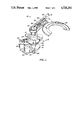
- FIG. 2 is a side elevational view of the drive assembly of the workpiece transfer apparatus, shown in cross-section.
- FIG. 3 is a side elevational view of the transfer arm assembly of the workpiece transfer apparatus, shown in cross-section.
- FIG. 4 is a schematic view illustrating rotation of the transfer arm assembly at a constant radius.
- FIG. 5 is a schematic view illustrating translation of the workpiece transfer assembly along a straight line.
- the apparatus 10 includes a drive assembly 12 and a transfer arm assembly 14.
- the drive assembly 12 is mounted in a housing H, which is typically a loadlock such as that described in U.S. Pat. No. 4,483,654, the disclosure of which is incorporated herein by reference.
- the utility of the workpiece transfer apparatus 10 of the present invention is not limited to use in loadlocks, although its design offers particular advantages when employed in low pressure environments.
- the drive assembly 12 includes an upper bearing assembly 16 and a lower bearing assembly 18. All references to upper and lower directions will be made relative to the orientation of the apparatus 10 in the drawings.
- the upper bearing assembly 16 includes an outer shell 20 (including a cylindrical body 20a and cover 20b) which penetrates an opening 22 through a wall of the housing H.
- the shell 20 is fixed to the housing H and will not move relative thereto.
- a seal cap 23 is provided to retain O-rings 25 and spacer 26, as described hereinafter.
- a pulley 24 is formed integrally at the lower end of the bearing shell 20 for the reasons set forth more fully hereinbelow.
- a sleeve 30 is rotatably received within the upper bearing assembly 16 on a plurality of ball bearings 32.
- the sleeve 30 is free to rotate relative to the outer shell 20 of the upper bearing assembly 16 as well as the housing H.
- a dynamic seal between the sleeve 30 and the shell 20 is provided by O-rings 25 and spacer 26.
- the O-rings 25 protect the vacuum inside the housing H from leakage through the sole penetration 22 required by the apparatus 10.
- a shaft 36 is mounted coaxially within the center of sleeve 30 and held in place at its upper end by a bearing 38 and at its lower end by bracket 40.
- a pulley 42 is mounted on the upper end of the shaft 36 and is located within the transfer arm assembly 14, as will be described in more detail hereinafter.
- the lower bearing assembly 18 is mounted on sleeve 30 by a plurality of ball bearings 46 so that outer shell 48 is free to rotate relative to the sleeve.
- a first drive motor 50 typically an electric stepper motor or DC servo motor, is mounted on a bracket 52 which is secured to the upper end of shell 48 of the lower bearing assembly 18.
- a belt 54 e.g., a timing belt, extends between spindle 56 on motor 50 and pulley 24 on the upper bearing assembly 16.
- actuation of the motor 50 will cause rotation of the outershell 48 of the lower bearing assembly 18 relative to the upper bearing assembly 16 as well as the housing H.
- the shaft 36 is directly connected to the lower bearing assembly 18 by bracket 40 and post 58, the shaft will be caused to rotate synchronously with the lower bearing assembly 18 as caused by drive motor 50.
- a second drive motor 60 which will usually be an electric stepper motor or DC servo motor, is also secured to the lower bearing assembly 18, conveniently by a bracket 62.
- Spindle 64 of motor 60 is connected to a pulley 66, formed on the lower end of sleeve 30, by a belt 68, typically a timing belt.
- actuation of second motor 60 causes the sleeve 30 to rotate relative to the lower assembly 18. So long as lower bearing assembly 18 remains stationary, of course, rotation of sleeve 30 relative to the upper bearing assembly 16 and housing H will also be effected by drive motor 60.
- worm drive gears are advantageous because of their positive action and resistance to wear and stretching which are frequently found with other types of drives.
- the transfer arm assembly 14 includes a linking arm enclosure 70 which is attached to the upper end of sleeve 30 by a mounting collar 72.
- a bearing assembly 74 is mounted in the distal end of the enclosure 70 and includes a output shaft 76.
- Shaft 76 extends through a port 77 in the linking arm enclosure 70 and is connected to pulley 78, and a belt 80, e.g., a timing belt, connects pulley 78 to pulley 42 on shaft 36.
- Port 77 is the sole penetration of the linking arm enclosure 70, and O-ring 82 is provided around shaft 76 to prevent leakage through the penetration.
- a timing belt as illustrated, it may sometimes be preferable to couple the pulley 42 and pulley 48 using a high strength cable which is resistant to stretching.
- An idler roller 84 is mounted on a spring loaded carrier bracket 86 which in turn is mounted on pin 88 in the interior of the housing 70.
- the idler roller 84 presses against the timing belt 80 in order to take up slack according to conventional principles.
- the present invention may employ a pair of opposed pinch rollers (not illustrated) to take up slack in the timing belt.
- the opposed rollers have the advantage that the slack is taken up evenly on both sides so that the timing belt is not thrown out of synchronization.
- Wafer transport arm 90 (FIG. 1) is mounted with its proximal end 92 secured to pin 76, so that said arm will rotate with the pin.
- the distal end of transport art 90 is shaped in order to support single silicon wafers in a well known manner.
- the construction of the workpiece transport apparatus 10 is particularly well suited for operation in low pressure environments, requiring only two dynamic seals.
- the first seal is provided by O-rings 25 and spacer 26 in the upper bearing assembly 16. This seal allows rotation of the sleeve 30 while maintaining isolation of the interior of the housing H.
- the only other dynamic seal is provided by O-ring 82 on the rotating pin 76. With these seals, the interior of the linking arm enclosure 70 will be at ambient pressure and isolated from the interior of the loadlock, avoiding the lubrication and particulate generation problems discussed above.
- FIG. 4 rotation of the wafer transport arm 94 at a constant radius R 1 is illustrated.
- the transport arm assembly 14 is initially in the position shown in full line.
- Rotation spindle 56 on first drive motor 50 in the clockwise direction causes lower bearing assembly 18 to rotate in the opposite direction, ultimately causing linking arm enclosure 70 to rotate in a counterclockwise direction.
- the relative angle between enclosure 70 and transport arm 94 remains constant since the shaft 36 is rotated by an identical amount as the assembly 18 and the sleeve 30.
- FIG. 5 illustrates the situation in which the distal end of the wafer transport arm 94 is moved radially inward and outward along a straight line.
- Radial translation of the transport arm 94 is effected by rotation of the second drive motor 60 which causes the sleeve 30 to rotate relative to shaft 36.
- Rotation of sleeve 30, causes linking arm enclosure 70 to rotate, which further causes pulley 78 to rotate relative to pulley 42.
- pulley 42 is fixed, however, pulley 78 will be caused to rotate at a fixed angular velocity, depending on the ratio of the diameters of pulley 42 and pulley 78.
- pulley 42 has a diameter which is exactly twice that of pulley 78, causing transfer arm 94 to articulate at an angular velocity twice that of linking arm enclosure 70.
- the distal end of the wafer arm 94 can be positioned precisely at any position within the maximum extension of the workpiece transport apparatus 10.
- the radial position is adjusted by motor 60, while the angular position is adjusted by motor 50.
- Such positioning can be accomplished by digital control systems as are well known in the art. The use of digital control systems allows virtually any transfer path to be traced by the concurrent operation of both motors 50 and 60.
Abstract
Description
Claims (21)
Priority Applications (1)
| Application Number | Priority Date | Filing Date | Title |
|---|---|---|---|
| US06/899,563 US4728252A (en) | 1986-08-22 | 1986-08-22 | Wafer transport mechanism |
Applications Claiming Priority (1)
| Application Number | Priority Date | Filing Date | Title |
|---|---|---|---|
| US06/899,563 US4728252A (en) | 1986-08-22 | 1986-08-22 | Wafer transport mechanism |
Publications (1)
| Publication Number | Publication Date |
|---|---|
| US4728252A true US4728252A (en) | 1988-03-01 |
Family
ID=25411223
Family Applications (1)
| Application Number | Title | Priority Date | Filing Date |
|---|---|---|---|
| US06/899,563 Expired - Lifetime US4728252A (en) | 1986-08-22 | 1986-08-22 | Wafer transport mechanism |
Country Status (1)
| Country | Link |
|---|---|
| US (1) | US4728252A (en) |
Cited By (41)
| Publication number | Priority date | Publication date | Assignee | Title |
|---|---|---|---|---|
| US4813846A (en) * | 1987-02-13 | 1989-03-21 | Leybold-Heraeus Gmbh | Inserting device for vacuum apparatus |
| US4837919A (en) * | 1987-09-17 | 1989-06-13 | Maho Aktiengesellschaft | Tool changing assembly for universal milling and drilling machines |
| US4862980A (en) * | 1988-10-06 | 1989-09-05 | Quest Systems, Inc. | Walking machine |
| EP0426859A1 (en) * | 1989-03-02 | 1991-05-15 | Fanuc Ltd. | Articulation structure for industrial robots |
| US5030056A (en) * | 1988-12-02 | 1991-07-09 | Tokyo Electron Sagami Ltd. | Substrate transfer device |
| US5049029A (en) * | 1987-09-10 | 1991-09-17 | Tokyo Electron Limited | Handling apparatus for transferring a semiconductor wafer or LCD |
| US5085553A (en) * | 1987-07-14 | 1992-02-04 | U.S. Philips Corporation | Device for the transport of carriers from and to a positioning device and selection device for use in such a device |
| US5249904A (en) * | 1987-12-01 | 1993-10-05 | Tsubakimoto Chain Co. | Stock handling apparatus |
| EP0563382A1 (en) * | 1991-10-17 | 1993-10-06 | Kabushiki Kaisha Yaskawa Denki | Arm driving device of industrial robot |
| WO1997002933A1 (en) * | 1995-07-10 | 1997-01-30 | Kensington Laboratories, Inc. | Dual end effector, multiple link robot arm system with corner reacharound and extended reach capabilities |
| WO1997002932A1 (en) * | 1995-07-10 | 1997-01-30 | Kensington Laboratories, Inc. | Continuously rotatable multiple link robot arm mechanism |
| WO1997003395A1 (en) * | 1995-07-10 | 1997-01-30 | Smart Machines | Direct driven robot |
| WO1998002284A1 (en) * | 1996-07-15 | 1998-01-22 | Brooks Automation Inc. | Batch loader arm |
| US5725352A (en) * | 1993-11-22 | 1998-03-10 | Sony Corporation | Multi-articulate arm type transport device |
| US5794487A (en) * | 1995-07-10 | 1998-08-18 | Smart Machines | Drive system for a robotic arm |
| US5816770A (en) * | 1996-01-23 | 1998-10-06 | Itagaki; Yasuhito | Transfer robot |
| US5836735A (en) * | 1996-03-13 | 1998-11-17 | Storage Technology Corporation | Robot powered pass thru port for automated cartridge library |
| EP0888581A1 (en) * | 1996-03-22 | 1999-01-07 | Genmark Automation, Inc. | Robot having multiple degrees of freedom |
| EP0923111A2 (en) * | 1997-12-07 | 1999-06-16 | ESEC Management SA | Semiconductor mounting apparatus with a reciprocating chip gripper |
| US6022185A (en) * | 1992-08-18 | 2000-02-08 | Tokyo Electron Limited | Substrate transferring device |
| EP0980301A1 (en) * | 1996-09-20 | 2000-02-23 | Brooks Automation, Inc. | Coaxial drive loader arm |
| US6068438A (en) * | 1996-08-05 | 2000-05-30 | Barry; Leonard D. | Cargo-container crane and system |
| US6230721B1 (en) * | 1996-10-30 | 2001-05-15 | Shibaura Mechatronics Corporation | Processing apparatus and method, robot apparatus |
| WO2003006216A1 (en) * | 2001-07-13 | 2003-01-23 | Brooks Automation, Inc. | Substrate transport apparatus with multiple independent end effectors |
| WO2003007340A2 (en) * | 2001-07-13 | 2003-01-23 | Axcelis Technologies, Inc. | Wafer transport apparatus |
| US6705816B2 (en) | 2000-06-09 | 2004-03-16 | Waypoint Technologies | Wafer transport mechanism |
| US20040148048A1 (en) * | 2002-11-11 | 2004-07-29 | Farnworth Warren M. | Methods for recognizing features as one or more objects are being fabricated by programmed material consolidation techniques |
| US20070020081A1 (en) * | 2005-07-11 | 2007-01-25 | Ulysses Gilchrist | Substrate transport apparatus |
| US20070089557A1 (en) * | 2004-09-30 | 2007-04-26 | Solomon Todd R | Multi-ply strap drive trains for robotic arms |
| USRE41266E1 (en) | 1990-09-18 | 2010-04-27 | Lam Research Corporation | Composite electrode for plasma processes |
| US20100126293A1 (en) * | 2008-11-21 | 2010-05-27 | Comau Inc. | Robotic radial tool positioning system |
| US20120141237A1 (en) * | 2004-12-22 | 2012-06-07 | Mike Rice | Substrate processing sequence in a cartesian robot cluster tool |
| US20130047771A1 (en) * | 2011-08-25 | 2013-02-28 | Hon Hai Precision Industry Co., Ltd. | Robot with cable protection structure |
| US8550031B2 (en) | 2004-12-22 | 2013-10-08 | Applied Materials, Inc. | Cluster tool architecture for processing a substrate |
| CN104070521A (en) * | 2014-07-02 | 2014-10-01 | 安徽埃夫特智能装备有限公司 | Robot shaft installation structure |
| US10449011B2 (en) | 2004-09-30 | 2019-10-22 | Intuitive Surgical Operations, Inc. | Offset remote center manipulator for robotic surgery |
| US10595948B2 (en) | 2004-09-30 | 2020-03-24 | Intuitive Surgical Operations, Inc. | Methods and apparatus for stacked electro-mechancial straps in robotic arms |
| US11244846B2 (en) | 2018-05-18 | 2022-02-08 | Applied Materials, Inc. | Multi-blade robot apparatus, electronic device manufacturing apparatus, and methods adapted to transport multiple substrates in electronic device manufacturing |
| US20220111513A1 (en) * | 2020-10-14 | 2022-04-14 | Applied Materials, Inc. | Infinite rotation of vacuum robot linkage through timing belt with isolated environment |
| CN114620447A (en) * | 2022-04-26 | 2022-06-14 | 北京半导体专用设备研究所(中国电子科技集团公司第四十五研究所) | Substrate transfer device |
| US20230118334A1 (en) * | 2021-10-15 | 2023-04-20 | Seiko Epson Corporation | Robot And Adjusting Method |
Citations (24)
| Publication number | Priority date | Publication date | Assignee | Title |
|---|---|---|---|---|
| US25889A (en) * | 1859-10-25 | Improvement in seed-planters | ||
| US3010587A (en) * | 1957-09-20 | 1961-11-28 | Richard G Hollinger | Workpiece transfer mechanism |
| US3363474A (en) * | 1964-07-08 | 1968-01-16 | Evg Entwicklung Verwert Ges | Straight guiding device |
| US3656454A (en) * | 1970-11-23 | 1972-04-18 | Air Reduction | Vacuum coating apparatus |
| US3874525A (en) * | 1973-06-29 | 1975-04-01 | Ibm | Method and apparatus for handling workpieces |
| GB1395058A (en) * | 1972-11-07 | 1975-05-21 | Sahlin Automation Ltd | Work feeding apparatus |
| SU595224A1 (en) * | 1976-04-22 | 1978-02-28 | Ленинградский технологический институт холодильной промышленности | Inertia-type conveyer |
| GB2022047A (en) * | 1978-06-06 | 1979-12-12 | Shiroyama Kogyo Kk | A Jointed Manipulator with Controlled Play Indexing |
| GB1570066A (en) * | 1976-12-16 | 1980-06-25 | Dobson C | Fluid tight locks |
| JPS55116432A (en) * | 1979-03-02 | 1980-09-08 | Anelva Corp | Vacuum apparatus |
| US4392776A (en) * | 1981-05-15 | 1983-07-12 | Westinghouse Electric Corp. | Robotic manipulator structure |
| US4398863A (en) * | 1981-05-15 | 1983-08-16 | Westinghouse Electric Corp. | Pick and place robot |
| GB2121747A (en) * | 1982-04-16 | 1984-01-04 | Sahlin Int Inc | Apparatus for loading and/or unloading industrial presses or the like |
| US4433951A (en) * | 1981-02-13 | 1984-02-28 | Lam Research Corporation | Modular loadlock |
| US4483654A (en) * | 1981-02-13 | 1984-11-20 | Lam Research Corporation | Workpiece transfer mechanism |
| DE3326962A1 (en) * | 1983-07-27 | 1985-02-07 | Josef 4790 Paderborn Göllner jun. | INDUSTRIAL ROBOT WITH TWO-PIECE JOINT ARM |
| US4552505A (en) * | 1982-11-19 | 1985-11-12 | American Robot Corporation | Industrial robot having direct coaxial motor drive |
| US4584045A (en) * | 1984-02-21 | 1986-04-22 | Plasma-Therm, Inc. | Apparatus for conveying a semiconductor wafer |
| WO1986003158A1 (en) * | 1984-11-26 | 1986-06-05 | Fanuc Ltd | Industrial robot having explosion-preventing structure |
| DE3511531A1 (en) * | 1985-03-29 | 1986-10-09 | Audi AG, 8070 Ingolstadt | Apparatus for relocating articles |
| US4619575A (en) * | 1985-01-28 | 1986-10-28 | Mid-West Conveyor Company, Inc. | Apparatus for storage and retrieval of thin trays and sheets |
| US4687542A (en) * | 1985-10-24 | 1987-08-18 | Texas Instruments Incorporated | Vacuum processing system |
| US4693666A (en) * | 1984-07-27 | 1987-09-15 | Westinghouse Electric Corp. | SCARA type manipulator apparatus |
| US4695215A (en) * | 1982-05-25 | 1987-09-22 | Ernst Leitz Wetzlar Gmbh | Device for automatically transporting disk shaped objects |
-
1986
- 1986-08-22 US US06/899,563 patent/US4728252A/en not_active Expired - Lifetime
Patent Citations (24)
| Publication number | Priority date | Publication date | Assignee | Title |
|---|---|---|---|---|
| US25889A (en) * | 1859-10-25 | Improvement in seed-planters | ||
| US3010587A (en) * | 1957-09-20 | 1961-11-28 | Richard G Hollinger | Workpiece transfer mechanism |
| US3363474A (en) * | 1964-07-08 | 1968-01-16 | Evg Entwicklung Verwert Ges | Straight guiding device |
| US3656454A (en) * | 1970-11-23 | 1972-04-18 | Air Reduction | Vacuum coating apparatus |
| GB1395058A (en) * | 1972-11-07 | 1975-05-21 | Sahlin Automation Ltd | Work feeding apparatus |
| US3874525A (en) * | 1973-06-29 | 1975-04-01 | Ibm | Method and apparatus for handling workpieces |
| SU595224A1 (en) * | 1976-04-22 | 1978-02-28 | Ленинградский технологический институт холодильной промышленности | Inertia-type conveyer |
| GB1570066A (en) * | 1976-12-16 | 1980-06-25 | Dobson C | Fluid tight locks |
| GB2022047A (en) * | 1978-06-06 | 1979-12-12 | Shiroyama Kogyo Kk | A Jointed Manipulator with Controlled Play Indexing |
| JPS55116432A (en) * | 1979-03-02 | 1980-09-08 | Anelva Corp | Vacuum apparatus |
| US4483654A (en) * | 1981-02-13 | 1984-11-20 | Lam Research Corporation | Workpiece transfer mechanism |
| US4433951A (en) * | 1981-02-13 | 1984-02-28 | Lam Research Corporation | Modular loadlock |
| US4392776A (en) * | 1981-05-15 | 1983-07-12 | Westinghouse Electric Corp. | Robotic manipulator structure |
| US4398863A (en) * | 1981-05-15 | 1983-08-16 | Westinghouse Electric Corp. | Pick and place robot |
| GB2121747A (en) * | 1982-04-16 | 1984-01-04 | Sahlin Int Inc | Apparatus for loading and/or unloading industrial presses or the like |
| US4695215A (en) * | 1982-05-25 | 1987-09-22 | Ernst Leitz Wetzlar Gmbh | Device for automatically transporting disk shaped objects |
| US4552505A (en) * | 1982-11-19 | 1985-11-12 | American Robot Corporation | Industrial robot having direct coaxial motor drive |
| DE3326962A1 (en) * | 1983-07-27 | 1985-02-07 | Josef 4790 Paderborn Göllner jun. | INDUSTRIAL ROBOT WITH TWO-PIECE JOINT ARM |
| US4584045A (en) * | 1984-02-21 | 1986-04-22 | Plasma-Therm, Inc. | Apparatus for conveying a semiconductor wafer |
| US4693666A (en) * | 1984-07-27 | 1987-09-15 | Westinghouse Electric Corp. | SCARA type manipulator apparatus |
| WO1986003158A1 (en) * | 1984-11-26 | 1986-06-05 | Fanuc Ltd | Industrial robot having explosion-preventing structure |
| US4619575A (en) * | 1985-01-28 | 1986-10-28 | Mid-West Conveyor Company, Inc. | Apparatus for storage and retrieval of thin trays and sheets |
| DE3511531A1 (en) * | 1985-03-29 | 1986-10-09 | Audi AG, 8070 Ingolstadt | Apparatus for relocating articles |
| US4687542A (en) * | 1985-10-24 | 1987-08-18 | Texas Instruments Incorporated | Vacuum processing system |
Cited By (87)
| Publication number | Priority date | Publication date | Assignee | Title |
|---|---|---|---|---|
| US4813846A (en) * | 1987-02-13 | 1989-03-21 | Leybold-Heraeus Gmbh | Inserting device for vacuum apparatus |
| US5085553A (en) * | 1987-07-14 | 1992-02-04 | U.S. Philips Corporation | Device for the transport of carriers from and to a positioning device and selection device for use in such a device |
| US5049029A (en) * | 1987-09-10 | 1991-09-17 | Tokyo Electron Limited | Handling apparatus for transferring a semiconductor wafer or LCD |
| US4837919A (en) * | 1987-09-17 | 1989-06-13 | Maho Aktiengesellschaft | Tool changing assembly for universal milling and drilling machines |
| US5249904A (en) * | 1987-12-01 | 1993-10-05 | Tsubakimoto Chain Co. | Stock handling apparatus |
| US4862980A (en) * | 1988-10-06 | 1989-09-05 | Quest Systems, Inc. | Walking machine |
| US5030056A (en) * | 1988-12-02 | 1991-07-09 | Tokyo Electron Sagami Ltd. | Substrate transfer device |
| EP0426859A1 (en) * | 1989-03-02 | 1991-05-15 | Fanuc Ltd. | Articulation structure for industrial robots |
| EP0426859A4 (en) * | 1989-03-02 | 1992-11-25 | Fanuc Ltd. | Articulation structure for industrial robots |
| USRE41266E1 (en) | 1990-09-18 | 2010-04-27 | Lam Research Corporation | Composite electrode for plasma processes |
| EP0563382A4 (en) * | 1991-10-17 | 1994-03-30 | Kabushiki Kaisha Yaskawa Denki | |
| EP0563382A1 (en) * | 1991-10-17 | 1993-10-06 | Kabushiki Kaisha Yaskawa Denki | Arm driving device of industrial robot |
| US6022185A (en) * | 1992-08-18 | 2000-02-08 | Tokyo Electron Limited | Substrate transferring device |
| US5725352A (en) * | 1993-11-22 | 1998-03-10 | Sony Corporation | Multi-articulate arm type transport device |
| WO1997002933A1 (en) * | 1995-07-10 | 1997-01-30 | Kensington Laboratories, Inc. | Dual end effector, multiple link robot arm system with corner reacharound and extended reach capabilities |
| WO1997002932A1 (en) * | 1995-07-10 | 1997-01-30 | Kensington Laboratories, Inc. | Continuously rotatable multiple link robot arm mechanism |
| WO1997003395A1 (en) * | 1995-07-10 | 1997-01-30 | Smart Machines | Direct driven robot |
| US6428266B1 (en) | 1995-07-10 | 2002-08-06 | Brooks Automation, Inc. | Direct driven robot |
| US5741113A (en) * | 1995-07-10 | 1998-04-21 | Kensington Laboratories, Inc. | Continuously rotatable multiple link robot arm mechanism |
| US5765444A (en) * | 1995-07-10 | 1998-06-16 | Kensington Laboratories, Inc. | Dual end effector, multiple link robot arm system with corner reacharound and extended reach capabilities |
| US5794487A (en) * | 1995-07-10 | 1998-08-18 | Smart Machines | Drive system for a robotic arm |
| US5816770A (en) * | 1996-01-23 | 1998-10-06 | Itagaki; Yasuhito | Transfer robot |
| US5836735A (en) * | 1996-03-13 | 1998-11-17 | Storage Technology Corporation | Robot powered pass thru port for automated cartridge library |
| EP0888581A1 (en) * | 1996-03-22 | 1999-01-07 | Genmark Automation, Inc. | Robot having multiple degrees of freedom |
| EP0888581A4 (en) * | 1996-03-22 | 2006-10-18 | Genmark Automation Inc | Robot having multiple degrees of freedom |
| US5954472A (en) * | 1996-07-15 | 1999-09-21 | Brooks Automation, Inc. | Batch loader arm |
| WO1998002284A1 (en) * | 1996-07-15 | 1998-01-22 | Brooks Automation Inc. | Batch loader arm |
| US6068438A (en) * | 1996-08-05 | 2000-05-30 | Barry; Leonard D. | Cargo-container crane and system |
| EP0980301A1 (en) * | 1996-09-20 | 2000-02-23 | Brooks Automation, Inc. | Coaxial drive loader arm |
| EP0980301A4 (en) * | 1996-09-20 | 2000-05-17 | Brooks Automation Inc | Coaxial drive loader arm |
| US6230721B1 (en) * | 1996-10-30 | 2001-05-15 | Shibaura Mechatronics Corporation | Processing apparatus and method, robot apparatus |
| EP0923111A2 (en) * | 1997-12-07 | 1999-06-16 | ESEC Management SA | Semiconductor mounting apparatus with a reciprocating chip gripper |
| KR100550049B1 (en) * | 1997-12-07 | 2006-10-04 | 언액시스 인터내셔널 트레이딩 엘티디 | Semi-conductor mounting apparatus with a chip gripper traveling back and forth |
| EP0923111A3 (en) * | 1997-12-07 | 2004-12-29 | ESEC Trading SA | Semiconductor mounting apparatus with a reciprocating chip gripper |
| US6705816B2 (en) | 2000-06-09 | 2004-03-16 | Waypoint Technologies | Wafer transport mechanism |
| WO2003007340A3 (en) * | 2001-07-13 | 2003-11-27 | Axcelis Tech Inc | Wafer transport apparatus |
| US6663333B2 (en) | 2001-07-13 | 2003-12-16 | Axcelis Technologies, Inc. | Wafer transport apparatus |
| US20040052632A1 (en) * | 2001-07-13 | 2004-03-18 | Kinnard David William | Wafer transport apparatus |
| US20040076505A1 (en) * | 2001-07-13 | 2004-04-22 | Kinnard David William | Wafer transport apparatus |
| WO2003007340A2 (en) * | 2001-07-13 | 2003-01-23 | Axcelis Technologies, Inc. | Wafer transport apparatus |
| CN1320595C (en) * | 2001-07-13 | 2007-06-06 | 艾克塞利斯技术公司 | Wafer transport apparatus |
| WO2003006216A1 (en) * | 2001-07-13 | 2003-01-23 | Brooks Automation, Inc. | Substrate transport apparatus with multiple independent end effectors |
| US6969227B2 (en) | 2001-07-13 | 2005-11-29 | Axcolis Technologies, Inc. | Wafer transport apparatus |
| US6877946B2 (en) | 2001-07-13 | 2005-04-12 | Axcelis Technologies, Inc. | Wafer transport apparatus |
| US20040159340A1 (en) * | 2002-11-11 | 2004-08-19 | Hiatt William M. | Methods for removing and reclaiming unconsolidated material from substrates following fabrication of objects thereon by programmed material consolidation techniques |
| US20070179655A1 (en) * | 2002-11-11 | 2007-08-02 | Farnworth Warren M | Methods and apparatus for calibrating programmable material consolidation apparatus |
| US20040167663A1 (en) * | 2002-11-11 | 2004-08-26 | Hiatt William M. | Handling system for use with programmable material consolidation systems and associated methods |
| US20050049751A1 (en) * | 2002-11-11 | 2005-03-03 | Farnworth Warren M. | Machine vision systems for use with programmable material consolidation apparatus and systems |
| US20040164461A1 (en) * | 2002-11-11 | 2004-08-26 | Ahmad Syed Sajid | Programmed material consolidation systems including multiple fabrication sites and associated methods |
| US20040159344A1 (en) * | 2002-11-11 | 2004-08-19 | Hiatt William M. | Cleaning components for use with programmable material consolidation apparatus and systems |
| US20040159967A1 (en) * | 2002-11-11 | 2004-08-19 | Farnworth Warren M. | Bubble elimination system for use with stereolithography apparatus and bubble elimination methods |
| US20060226579A1 (en) * | 2002-11-11 | 2006-10-12 | Farnworth Warren M | Methods for removing gas and gas bubbles from liquid materials to be used in programmed material consolidation processes |
| US20040158343A1 (en) * | 2002-11-11 | 2004-08-12 | Hiatt William M. | Methods for supporting substrates during fabrication of one or more objects thereon by programmable material consolidation techniques |
| US20040186608A1 (en) * | 2002-11-11 | 2004-09-23 | Hiatt William M. | Substrate supports for use with programmable material consolidation apparatus and systems |
| US20040148048A1 (en) * | 2002-11-11 | 2004-07-29 | Farnworth Warren M. | Methods for recognizing features as one or more objects are being fabricated by programmed material consolidation techniques |
| US7225044B2 (en) | 2002-11-11 | 2007-05-29 | Micron Technology, Inc. | Methods for supporting substrates during fabrication of one or more objects thereon by programmable material consolidation techniques |
| US20040153193A1 (en) * | 2002-11-11 | 2004-08-05 | Farnworth Warren M. | Methods and apparatus for calibrating programmable material consolidation apparatus |
| US7239932B2 (en) | 2002-11-11 | 2007-07-03 | Micron Technology, Inc. | Methods and apparatus for calibrating programmable material consolidation apparatus |
| US7239933B2 (en) | 2002-11-11 | 2007-07-03 | Micron Technology, Inc. | Substrate supports for use with programmable material consolidation apparatus and systems |
| US20070157952A1 (en) * | 2002-11-11 | 2007-07-12 | Hiatt William M | Methods for removing and reclaiming unconsolidated material from substrates following fabrication of objects thereon by programmed material consolidation techniques |
| US20070168074A1 (en) * | 2002-11-11 | 2007-07-19 | Hiatt William M | Methods for supporting substrates during fabrication of one or more objects thereon by programmed material consolidation techniques |
| US20070179654A1 (en) * | 2002-11-11 | 2007-08-02 | Hiatt William M | Substrate supports for use with programmable material consolidation apparatus and systems |
| US9803727B2 (en) | 2004-09-30 | 2017-10-31 | Intuitive Surgical Operations, Inc. | Strap guide system and methods thereof for robotic surgical arms |
| US20070089557A1 (en) * | 2004-09-30 | 2007-04-26 | Solomon Todd R | Multi-ply strap drive trains for robotic arms |
| US11160626B2 (en) | 2004-09-30 | 2021-11-02 | Intuitive Surgical Operations, Inc. | Offset remote center manipulator for robotic surgery |
| US10646292B2 (en) | 2004-09-30 | 2020-05-12 | Intuitive Surgical Operations, Inc. | Electro-mechanical strap stack in robotic arms |
| US20130239392A1 (en) * | 2004-09-30 | 2013-09-19 | Intuitive Surgical Operations, Inc. | Method for robotic arms with strap drive trains |
| US10595948B2 (en) | 2004-09-30 | 2020-03-24 | Intuitive Surgical Operations, Inc. | Methods and apparatus for stacked electro-mechancial straps in robotic arms |
| US10449011B2 (en) | 2004-09-30 | 2019-10-22 | Intuitive Surgical Operations, Inc. | Offset remote center manipulator for robotic surgery |
| US9068628B2 (en) | 2004-09-30 | 2015-06-30 | Intuitive Surgical Operations, Inc. | Robotic arms with strap drive trains |
| US9261172B2 (en) * | 2004-09-30 | 2016-02-16 | Intuitive Surgical Operations, Inc. | Multi-ply strap drive trains for surgical robotic arms |
| US9797484B2 (en) * | 2004-09-30 | 2017-10-24 | Intuitive Surgical Operations, Inc. | Methods for robotic arms with strap drive trains |
| US20120141237A1 (en) * | 2004-12-22 | 2012-06-07 | Mike Rice | Substrate processing sequence in a cartesian robot cluster tool |
| US8550031B2 (en) | 2004-12-22 | 2013-10-08 | Applied Materials, Inc. | Cluster tool architecture for processing a substrate |
| US8911193B2 (en) * | 2004-12-22 | 2014-12-16 | Applied Materials, Inc. | Substrate processing sequence in a cartesian robot cluster tool |
| US20070020081A1 (en) * | 2005-07-11 | 2007-01-25 | Ulysses Gilchrist | Substrate transport apparatus |
| US10065307B2 (en) | 2005-07-11 | 2018-09-04 | Brooks Automation Inc. | Substrate transport apparatus |
| US8573919B2 (en) | 2005-07-11 | 2013-11-05 | Brooks Automation, Inc. | Substrate transport apparatus |
| US11426865B2 (en) | 2005-07-11 | 2022-08-30 | Brooks Automation Us, Llc | Substrate transport apparatus |
| US20100126293A1 (en) * | 2008-11-21 | 2010-05-27 | Comau Inc. | Robotic radial tool positioning system |
| US20130047771A1 (en) * | 2011-08-25 | 2013-02-28 | Hon Hai Precision Industry Co., Ltd. | Robot with cable protection structure |
| CN104070521A (en) * | 2014-07-02 | 2014-10-01 | 安徽埃夫特智能装备有限公司 | Robot shaft installation structure |
| US11244846B2 (en) | 2018-05-18 | 2022-02-08 | Applied Materials, Inc. | Multi-blade robot apparatus, electronic device manufacturing apparatus, and methods adapted to transport multiple substrates in electronic device manufacturing |
| US20220111513A1 (en) * | 2020-10-14 | 2022-04-14 | Applied Materials, Inc. | Infinite rotation of vacuum robot linkage through timing belt with isolated environment |
| US20230118334A1 (en) * | 2021-10-15 | 2023-04-20 | Seiko Epson Corporation | Robot And Adjusting Method |
| CN114620447A (en) * | 2022-04-26 | 2022-06-14 | 北京半导体专用设备研究所(中国电子科技集团公司第四十五研究所) | Substrate transfer device |
| CN114620447B (en) * | 2022-04-26 | 2024-01-26 | 北京半导体专用设备研究所(中国电子科技集团公司第四十五研究所) | Substrate transfer apparatus |
Similar Documents
| Publication | Publication Date | Title |
|---|---|---|
| US4728252A (en) | Wafer transport mechanism | |
| US10406679B2 (en) | Unequal link SCARA arm | |
| US5083896A (en) | Object handling device | |
| US4813846A (en) | Inserting device for vacuum apparatus | |
| KR100240458B1 (en) | Wafer transfer apparatus | |
| JP3341060B2 (en) | End station for parallel ion beam ion implanter | |
| US5355066A (en) | Two-axis magnetically coupled robot | |
| US5583408A (en) | Two-axis magnetically coupled robot | |
| KR101497169B1 (en) | Arm mechanism and vacuum robot having the same | |
| JP4723697B2 (en) | Direct drive robot | |
| US6155768A (en) | Multiple link robot arm system implemented with offset end effectors to provide extended reach and enhanced throughput | |
| US20030223853A1 (en) | Dual arm substrate transport apparatus | |
| KR101191074B1 (en) | Transfer apparatus and vacuum processing apparatus using the same | |
| US6293746B1 (en) | Transfer robot | |
| US6057662A (en) | Single motor control for substrate handler in processing system | |
| US5993142A (en) | Robot having multiple degrees of freedom in an isolated environment | |
| JPH1133951A (en) | Two arm type carrier robot device | |
| US5287616A (en) | Electronic component mounting apparatus | |
| JPH10296666A (en) | Carrying robot | |
| US6705816B2 (en) | Wafer transport mechanism | |
| JP2001269890A (en) | Conveying robot | |
| JP2622523B2 (en) | Magnetic levitation transfer device | |
| JPH03281183A (en) | Articulated conveying device | |
| JP2001118905A (en) | Carrying method and carrying equipment | |
| JPH04264748A (en) | Wafer transfer robot |
Legal Events
| Date | Code | Title | Description |
|---|---|---|---|
| AS | Assignment |
Owner name: LAM RESEARCH CORPORATION, A CORP OF CA.,CALIFORNIA Free format text: ASSIGNMENT OF ASSIGNORS INTEREST;ASSIGNORS:LADA, CHRISTOPHER O.;DEGNER, RAYMOND L.;LOBIANCO, ROBERT T.;REEL/FRAME:004594/0050 Effective date: 19860815 Owner name: LAM RESEARCH CORPORATION, 47655 WARM SPRINGS BLVD. Free format text: ASSIGNMENT OF ASSIGNORS INTEREST.;ASSIGNORS:LADA, CHRISTOPHER O.;DEGNER, RAYMOND L.;LOBIANCO, ROBERT T.;REEL/FRAME:004594/0050 Effective date: 19860815 |
|
| STCF | Information on status: patent grant |
Free format text: PATENTED CASE |
|
| FEPP | Fee payment procedure |
Free format text: PAYOR NUMBER ASSIGNED (ORIGINAL EVENT CODE: ASPN); ENTITY STATUS OF PATENT OWNER: LARGE ENTITY |
|
| FPAY | Fee payment |
Year of fee payment: 4 |
|
| FEPP | Fee payment procedure |
Free format text: PAYOR NUMBER ASSIGNED (ORIGINAL EVENT CODE: ASPN); ENTITY STATUS OF PATENT OWNER: LARGE ENTITY Free format text: PAYER NUMBER DE-ASSIGNED (ORIGINAL EVENT CODE: RMPN); ENTITY STATUS OF PATENT OWNER: LARGE ENTITY |
|
| FEPP | Fee payment procedure |
Free format text: PAT HLDR NO LONGER CLAIMS SMALL ENT STAT AS INDIV INVENTOR (ORIGINAL EVENT CODE: LSM1); ENTITY STATUS OF PATENT OWNER: LARGE ENTITY |
|
| FPAY | Fee payment |
Year of fee payment: 8 |
|
| FPAY | Fee payment |
Year of fee payment: 12 |