US4723574A - Sanitary water fitting - Google Patents
Sanitary water fitting Download PDFInfo
- Publication number
- US4723574A US4723574A US06/880,377 US88037786A US4723574A US 4723574 A US4723574 A US 4723574A US 88037786 A US88037786 A US 88037786A US 4723574 A US4723574 A US 4723574A
- Authority
- US
- United States
- Prior art keywords
- valve
- damping means
- piston
- handle assembly
- sanitary water
- Prior art date
- Legal status (The legal status is an assumption and is not a legal conclusion. Google has not performed a legal analysis and makes no representation as to the accuracy of the status listed.)
- Expired - Lifetime
Links
Images


Classifications
-
- F—MECHANICAL ENGINEERING; LIGHTING; HEATING; WEAPONS; BLASTING
- F16—ENGINEERING ELEMENTS AND UNITS; GENERAL MEASURES FOR PRODUCING AND MAINTAINING EFFECTIVE FUNCTIONING OF MACHINES OR INSTALLATIONS; THERMAL INSULATION IN GENERAL
- F16K—VALVES; TAPS; COCKS; ACTUATING-FLOATS; DEVICES FOR VENTING OR AERATING
- F16K19/00—Arrangements of valves and flow lines specially adapted for mixing fluids
-
- F—MECHANICAL ENGINEERING; LIGHTING; HEATING; WEAPONS; BLASTING
- F16—ENGINEERING ELEMENTS AND UNITS; GENERAL MEASURES FOR PRODUCING AND MAINTAINING EFFECTIVE FUNCTIONING OF MACHINES OR INSTALLATIONS; THERMAL INSULATION IN GENERAL
- F16K—VALVES; TAPS; COCKS; ACTUATING-FLOATS; DEVICES FOR VENTING OR AERATING
- F16K47/00—Means in valves for absorbing fluid energy
- F16K47/02—Means in valves for absorbing fluid energy for preventing water-hammer or noise
- F16K47/026—Means in valves for absorbing fluid energy for preventing water-hammer or noise preventing noise in a single handle mixing valve
-
- Y—GENERAL TAGGING OF NEW TECHNOLOGICAL DEVELOPMENTS; GENERAL TAGGING OF CROSS-SECTIONAL TECHNOLOGIES SPANNING OVER SEVERAL SECTIONS OF THE IPC; TECHNICAL SUBJECTS COVERED BY FORMER USPC CROSS-REFERENCE ART COLLECTIONS [XRACs] AND DIGESTS
- Y10—TECHNICAL SUBJECTS COVERED BY FORMER USPC
- Y10T—TECHNICAL SUBJECTS COVERED BY FORMER US CLASSIFICATION
- Y10T137/00—Fluid handling
- Y10T137/8593—Systems
- Y10T137/86493—Multi-way valve unit
- Y10T137/86549—Selective reciprocation or rotation
-
- Y—GENERAL TAGGING OF NEW TECHNOLOGICAL DEVELOPMENTS; GENERAL TAGGING OF CROSS-SECTIONAL TECHNOLOGIES SPANNING OVER SEVERAL SECTIONS OF THE IPC; TECHNICAL SUBJECTS COVERED BY FORMER USPC CROSS-REFERENCE ART COLLECTIONS [XRACs] AND DIGESTS
- Y10—TECHNICAL SUBJECTS COVERED BY FORMER USPC
- Y10T—TECHNICAL SUBJECTS COVERED BY FORMER US CLASSIFICATION
- Y10T137/00—Fluid handling
- Y10T137/8593—Systems
- Y10T137/86493—Multi-way valve unit
- Y10T137/86815—Multiple inlet with single outlet
Definitions
- the invention relates to a sanitary water fitting, particularly, in the form of a single handle mixer valve assembly with a control unit comprising discs, a piston, balls or the like, and with a damper for the closing action, to lengthen the closing time and reduce the closing speed.
- Single handle mixer valve assemblies are usually provided with valve control units fitted with aluminum oxide discs, balls or pistons. They are generally provided with a handle in the form of a lever or a knob to adjust water volume and temperature. Such valve assemblies are increasing in popularity since they are simple to operate and can control the water volume and temperature rapidly.
- Water hammer may be corrected by reducing the rate of flow in the pipe, thereby reducing the sound level
- Such devices to increase the closing time and to reduce the closing rate of the fittings are in the form of shock absorbers and are used in water supply systems, in industrial fittings, as well as in single handle mixer valve assemblies.
- a known assembly of this type, with control elements in disc form, provides for the movable sealing disc to be delayed by coupling a damper assembly to it.
- a disadvantage of such a solution is that the damper components inside the water fitting transmit sound created by naturally strong damping forces.
- Another disadvantage is that such a damper assembly for reducing the closing action is not easily repairable, nor is it generally replaceable.
- An object of the invention is to provide a sanitary water fitting of the above type, where the damper means for affecting the closing time of the valve is constructed separately from the valving components that control or guide the water.
- Another object of the invention is to provide damping means in which the damping forces are not transmitted by valving components of the fitting.
- a further object of the invention is to provide a damping means for a mixer valve assembly that is easy to replace or repair, and reliable in operation.
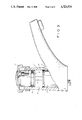
- FIGS. 1 and 2 are elevational views, partly in section, of a single lever valve fitting of a disc type, shown in its opened and closed position, respectively;
- FIGS. 3 and 4 are elevational views, partly in section of a single handle valve mixer of a piston type, shown in its opened and closed positions, respectively.
- FIGS. 1 and 2 illustrate a single lever mixer valve 1, of the lavatory type, and is shown in its opened and closed positions, respectively.
- Mixer valve 1 includes a control unit 3 having flat plates or discs as the valving mechanism, not shown. Control units of this type are shown in DT-AS 15 50 060.
- Control unit 3 mounted in valve housing H, is connected by a control lever 4 to cap-shaped portion 5 of hand lever 6.
- Hand lever 6 is pivotally coupled to control unit 3 and is shiftable vertically to adjust the water volume, and is rotatable to adjust the water temperature.
- a damping means 2 to control the closing action of the valve assembly 1, includes a rod-shaped piston 7 and a cylinder 8 which is mounted to the underside of cap-shaped portion 5 of hand lever 6. The outer end of piston 7 is biased against the top of control unit 3.
- FIGS. 3 and 4 illustrate a single-handle mixer valve 1', of the lavatory type, and is shown in its opened and closed positions, respectively.
- Mixer valve 1' includes a piston-type control unit 9 and is mounted in valve casing 14. Such piston-type control units are shown in DT-OS 32 24 991.
- Control unit 9 is operably coupled to a control lever 10 and to a cap-shaped handle 11.
- a damper means 2' for controlling the closing action of valve assembly 1', is operably coupled between the under surface of cap-shaped handle 11 and control unit 9.
- Damper means 2' includes a piston 12, which is housed in the underside of cap-shaped handle 11, or may be formed integral therewith, while cylinder 13 is housed in casing 14 of fitting 1', or may be integral therewith.
- the piston is mounted in sliding sealing engagement with the inner wall surface 15 of cylinder 13 by O-ring 16.
- valve assemblies 1,1' In operation, water volume of fittings 1,1' is adjusted by shifting cap-shaped handles 11 vertically, while the temperature is adjusted by rotating the handles, as illustrated in the direction of the arrows in FIGS. 1 and 4.
- Damping means 2,2' control the closing action of valve assemblies 1,1' by compressing air in cylinders 8,13 by pistons 7,12.
- Valve assemblies 1,1', made in accordance with the present invention, and having damping means 2,2' permit the closing action to be uniform in speed, thereby increasing the closing time, and reduce the closing speed, without any inconvenience to the user. Further, water hammer generally attributed to the fast closing action of various assemblies is obviated.
- valve assemblies described and illustrated herein, of the present invention are by way of example only. It is obvious that variations of design and operation are possible without departing from the invention herein, for example, damping means may be provided for valve fittings having a cold water valve and a hot water valve.
Abstract
Description
Claims (2)
Applications Claiming Priority (4)
| Application Number | Priority Date | Filing Date | Title |
|---|---|---|---|
| DE19853523350 DE3523350A1 (en) | 1985-06-29 | 1985-06-29 | SANITARY WATER FITTING |
| DE3523350 | 1985-06-29 | ||
| DE19858518983 DE8518983U1 (en) | 1985-06-29 | 1985-06-29 | Sanitary water tap |
| DE8518983[U] | 1985-06-29 |
Publications (1)
| Publication Number | Publication Date |
|---|---|
| US4723574A true US4723574A (en) | 1988-02-09 |
Family
ID=25833583
Family Applications (1)
| Application Number | Title | Priority Date | Filing Date |
|---|---|---|---|
| US06/880,377 Expired - Lifetime US4723574A (en) | 1985-06-29 | 1986-06-30 | Sanitary water fitting |
Country Status (1)
| Country | Link |
|---|---|
| US (1) | US4723574A (en) |
Cited By (7)
| Publication number | Priority date | Publication date | Assignee | Title |
|---|---|---|---|---|
| US4936347A (en) * | 1989-10-16 | 1990-06-26 | Suspa, Incorporated | Faucet actuator |
| US5082023A (en) * | 1989-10-31 | 1992-01-21 | Staar S. A. | Single-handle faucet |
| US5301716A (en) * | 1990-02-15 | 1994-04-12 | American Standard Inc. | Closure damper for a sanitary water fitting |
| US5413144A (en) * | 1991-06-17 | 1995-05-09 | Gustavsberg Vargarda Armatur Ab | Single-lever mixer valve provided with a device for preventing pressure shock at the closing movement of the lever |
| US20070267586A1 (en) * | 2006-05-19 | 2007-11-22 | Mei-Li Chen | Ceramic valve structure with slow-descending device |
| US20090044865A1 (en) * | 2007-08-16 | 2009-02-19 | Zurn Industries, Llc | Metering mixing faucet |
| US20100229985A1 (en) * | 2009-03-12 | 2010-09-16 | Piero Cattaneo | Cartridge including an anti-ram device |
Citations (10)
| Publication number | Priority date | Publication date | Assignee | Title |
|---|---|---|---|---|
| US697662A (en) * | 1901-09-21 | 1902-04-15 | Arnold K Reese | Combination safety regulating and drop valve. |
| US907951A (en) * | 1908-02-19 | 1908-12-29 | Carl Barr | Self-closing faucet or valve for lavatories or other fixtures. |
| US1298849A (en) * | 1914-10-23 | 1919-04-01 | Wolff Mfg Company L | Flushing device. |
| US2557287A (en) * | 1949-04-01 | 1951-06-19 | Scovill Manufacturing Co | Device for controlling time duration for operation of a valve |
| US2781519A (en) * | 1952-09-06 | 1957-02-19 | Rodney H Marchant | Flushing system |
| DE1127723B (en) * | 1954-08-26 | 1962-04-12 | Kloeckner Humboldt Deutz Ag | Valve for fire hoses |
| US3102711A (en) * | 1959-10-08 | 1963-09-03 | Sloan Valve Co | Flush valves |
| US3116917A (en) * | 1960-09-19 | 1964-01-07 | Holley Carburetor Co | Dashpot |
| US4112966A (en) * | 1976-11-29 | 1978-09-12 | Mark Controls Corporation | Ejector purge hydrant |
| DE2908882A1 (en) * | 1979-03-07 | 1980-09-11 | Ruppel | Automatic controlled water valve - has damping piston fixed to operating plunger to delay return to closed condition |
-
1986
- 1986-06-30 US US06/880,377 patent/US4723574A/en not_active Expired - Lifetime
Patent Citations (10)
| Publication number | Priority date | Publication date | Assignee | Title |
|---|---|---|---|---|
| US697662A (en) * | 1901-09-21 | 1902-04-15 | Arnold K Reese | Combination safety regulating and drop valve. |
| US907951A (en) * | 1908-02-19 | 1908-12-29 | Carl Barr | Self-closing faucet or valve for lavatories or other fixtures. |
| US1298849A (en) * | 1914-10-23 | 1919-04-01 | Wolff Mfg Company L | Flushing device. |
| US2557287A (en) * | 1949-04-01 | 1951-06-19 | Scovill Manufacturing Co | Device for controlling time duration for operation of a valve |
| US2781519A (en) * | 1952-09-06 | 1957-02-19 | Rodney H Marchant | Flushing system |
| DE1127723B (en) * | 1954-08-26 | 1962-04-12 | Kloeckner Humboldt Deutz Ag | Valve for fire hoses |
| US3102711A (en) * | 1959-10-08 | 1963-09-03 | Sloan Valve Co | Flush valves |
| US3116917A (en) * | 1960-09-19 | 1964-01-07 | Holley Carburetor Co | Dashpot |
| US4112966A (en) * | 1976-11-29 | 1978-09-12 | Mark Controls Corporation | Ejector purge hydrant |
| DE2908882A1 (en) * | 1979-03-07 | 1980-09-11 | Ruppel | Automatic controlled water valve - has damping piston fixed to operating plunger to delay return to closed condition |
Cited By (12)
| Publication number | Priority date | Publication date | Assignee | Title |
|---|---|---|---|---|
| US4936347A (en) * | 1989-10-16 | 1990-06-26 | Suspa, Incorporated | Faucet actuator |
| EP0424101A1 (en) * | 1989-10-16 | 1991-04-24 | Suspa,Incorporated | Faucet actuator |
| US5082023A (en) * | 1989-10-31 | 1992-01-21 | Staar S. A. | Single-handle faucet |
| US5301716A (en) * | 1990-02-15 | 1994-04-12 | American Standard Inc. | Closure damper for a sanitary water fitting |
| US5413144A (en) * | 1991-06-17 | 1995-05-09 | Gustavsberg Vargarda Armatur Ab | Single-lever mixer valve provided with a device for preventing pressure shock at the closing movement of the lever |
| US5570720A (en) * | 1991-06-17 | 1996-11-05 | Gustavsberg Vargarda Armatur Ab | Mixing valve of single lever type provided with a device for preventing pressure shock at closing movement of the lever |
| US20070267586A1 (en) * | 2006-05-19 | 2007-11-22 | Mei-Li Chen | Ceramic valve structure with slow-descending device |
| US7392972B2 (en) * | 2006-05-19 | 2008-07-01 | Mei-Li Chen | Ceramic valve structure with slow-descending device |
| US20090044865A1 (en) * | 2007-08-16 | 2009-02-19 | Zurn Industries, Llc | Metering mixing faucet |
| US8555922B2 (en) | 2007-08-16 | 2013-10-15 | Zurn Industries, Llc | Metering mixing faucet |
| US20100229985A1 (en) * | 2009-03-12 | 2010-09-16 | Piero Cattaneo | Cartridge including an anti-ram device |
| US8550424B2 (en) * | 2009-03-12 | 2013-10-08 | Piero Cattaneo | Cartridge including an anti-ram device |
Similar Documents
| Publication | Publication Date | Title |
|---|---|---|
| US6493904B1 (en) | Door closer | |
| EP0469697B1 (en) | Hydraulic door closer | |
| US4723574A (en) | Sanitary water fitting | |
| US4577653A (en) | Anti-siphon and anti-knock diverter valve | |
| TW200506259A (en) | Temperature control device | |
| ES2166734A1 (en) | Faucet for filling tanks | |
| TW287220B (en) | A controller | |
| CA2282037A1 (en) | Valve control system | |
| GB2365473A (en) | Apparatus for remote control of wellbore fluid flow | |
| CA1274447A (en) | Sanitary water fitting | |
| US4736772A (en) | Sanitary valve | |
| US2304323A (en) | Pressure operated throttling valve | |
| US4967998A (en) | Valve noise reduction | |
| US3342448A (en) | Self-closing faucet | |
| KR20010089348A (en) | Cartridge for single-handle mixer faucet | |
| US2871880A (en) | Single control handle operated mixing faucet having a diverter valve associated therewith | |
| US4723570A (en) | Water Faucet | |
| US5875807A (en) | Flow control especially for instantaneous water heater | |
| CN208734907U (en) | A kind of water valve realization time is adjustable, the adjustable leading push type structure of flow | |
| EP0551059B1 (en) | Cartridge for ceramic discs for mixing cocks | |
| EP0386613B1 (en) | A mixing valve with means for slowing down the closing action | |
| US2328010A (en) | Check valve | |
| JPS5838065Y2 (en) | Structure of antifreeze faucet | |
| WO2022242720A1 (en) | Reversible solenoid valve and air conditioning unit | |
| KR960006605Y1 (en) | Pressure control valve using air-discharge pressure |
Legal Events
| Date | Code | Title | Description |
|---|---|---|---|
| AS | Assignment |
Owner name: AMERICAN STANDARD INC., 40 WEST 40TH STREET, NEW Y Free format text: ASSIGNMENT OF ASSIGNORS INTEREST.;ASSIGNORS:BERGMANN, KONRAD;THULLEN, HANS W.;REEL/FRAME:004611/0703 Effective date: 19860627 Owner name: AMERICAN STANDARD INC., 40 WEST 40TH STREET, NEW Y Free format text: ASSIGNMENT OF ASSIGNORS INTEREST;ASSIGNORS:BERGMANN, KONRAD;THULLEN, HANS W.;REEL/FRAME:004611/0703 Effective date: 19860627 |
|
| STCF | Information on status: patent grant |
Free format text: PATENTED CASE |
|
| AS | Assignment |
Owner name: BANKERS TRUST COMPANY Free format text: SECURITY INTEREST;ASSIGNOR:AMERICAN STANDARD INC., A DE. CORP.,;REEL/FRAME:004905/0035 Effective date: 19880624 Owner name: BANKERS TRUST COMPANY, 4 ALBANY STREET 9TH FLOOR, Free format text: SECURITY INTEREST;ASSIGNOR:U.S. PLUMBING, INC., A CORPORATION OF DELAWARE;REEL/FRAME:004905/0159 Effective date: 19880624 Owner name: BANKERS TRUST COMPANY, NEW YORK Free format text: SECURITY INTEREST;ASSIGNOR:U.S. PLUMBING, INC., A CORPORATION OF DELAWARE;REEL/FRAME:004905/0159 Effective date: 19880624 |
|
| FEPP | Fee payment procedure |
Free format text: PAYOR NUMBER ASSIGNED (ORIGINAL EVENT CODE: ASPN); ENTITY STATUS OF PATENT OWNER: LARGE ENTITY |
|
| FPAY | Fee payment |
Year of fee payment: 4 |
|
| AS | Assignment |
Owner name: CHEMICAL BANK, AS COLLATERAL AGENT, NEW YORK Free format text: ASSIGNMENT OF SECURITY INTEREST;ASSIGNOR:BANKERS TRUST COMPANY, AS COLLATERAL TRUSTEE;REEL/FRAME:006565/0753 Effective date: 19930601 Owner name: CHEMICAL BANK, AS COLLATERAL AGENT, NEW YORK Free format text: ASSIGNMENT OF ASSIGNORS INTEREST;ASSIGNOR:AMERICAN STANDARD INC.;REEL/FRAME:006566/0170 Effective date: 19930601 |
|
| FPAY | Fee payment |
Year of fee payment: 8 |
|
| AS | Assignment |
Owner name: AMERICAN STANDARD, INC., NEW JERSEY Free format text: RELEASE OF SECURITY INTEREST (RE-RECORD TO CORRECT DUPLICATES SUBMITTED BY CUSTOMER. THE NEW SCHEDULE CHANGES THE TOTAL NUMBER OF PROPERTY NUMBERS INVOLVED FROM 1133 TO 794. THIS RELEASE OF SECURITY INTEREST WAS PREVIOUSLY RECORDED AT REEL 8869, FRAME 0001.);ASSIGNOR:CHASE MANHATTAN BANK, THE (FORMERLY KNOWN AS CHEMICAL BANK);REEL/FRAME:009123/0300 Effective date: 19970801 |
|
| AS | Assignment |
Owner name: AMERICAN STANDARD, INC., NEW JERSEY Free format text: RELEASE OF SECURITY INTEREST;ASSIGNOR:CHASE MANHATTAN BANK, THE (FORMERLY KNOWN AS CHEMICAL BANK);REEL/FRAME:008869/0001 Effective date: 19970801 |
|
| FPAY | Fee payment |
Year of fee payment: 12 |