US4708252A - Storage rack system - Google Patents
Storage rack system Download PDFInfo
- Publication number
- US4708252A US4708252A US06/867,897 US86789786A US4708252A US 4708252 A US4708252 A US 4708252A US 86789786 A US86789786 A US 86789786A US 4708252 A US4708252 A US 4708252A
- Authority
- US
- United States
- Prior art keywords
- column
- adjacent
- connector
- series
- slots
- Prior art date
- Legal status (The legal status is an assumption and is not a legal conclusion. Google has not performed a legal analysis and makes no representation as to the accuracy of the status listed.)
- Expired - Fee Related
Links
- 239000002184 metal Substances 0.000 claims description 14
- 230000013011 mating Effects 0.000 claims description 2
- 210000001331 nose Anatomy 0.000 claims 6
- 230000000712 assembly Effects 0.000 abstract description 34
- 238000000429 assembly Methods 0.000 abstract description 34
- 230000005484 gravity Effects 0.000 description 12
- 238000009434 installation Methods 0.000 description 7
- 230000033001 locomotion Effects 0.000 description 7
- 238000005452 bending Methods 0.000 description 6
- 238000010276 construction Methods 0.000 description 4
- 206010044565 Tremor Diseases 0.000 description 3
- 230000000694 effects Effects 0.000 description 3
- 238000009432 framing Methods 0.000 description 3
- 230000003042 antagnostic effect Effects 0.000 description 2
- 238000013461 design Methods 0.000 description 2
- 238000012546 transfer Methods 0.000 description 2
- 238000013519 translation Methods 0.000 description 2
- 230000014616 translation Effects 0.000 description 2
- 206010035148 Plague Diseases 0.000 description 1
- 241000607479 Yersinia pestis Species 0.000 description 1
- 230000010006 flight Effects 0.000 description 1
- 238000003197 gene knockdown Methods 0.000 description 1
- 239000000463 material Substances 0.000 description 1
- 238000005259 measurement Methods 0.000 description 1
- 238000000034 method Methods 0.000 description 1
- 239000011120 plywood Substances 0.000 description 1
- 238000012549 training Methods 0.000 description 1
Images


Classifications
-
- A—HUMAN NECESSITIES
- A47—FURNITURE; DOMESTIC ARTICLES OR APPLIANCES; COFFEE MILLS; SPICE MILLS; SUCTION CLEANERS IN GENERAL
- A47B—TABLES; DESKS; OFFICE FURNITURE; CABINETS; DRAWERS; GENERAL DETAILS OF FURNITURE
- A47B57/00—Cabinets, racks or shelf units, characterised by features for adjusting shelves or partitions
- A47B57/30—Cabinets, racks or shelf units, characterised by features for adjusting shelves or partitions with means for adjusting the height of detachable shelf supports
- A47B57/40—Cabinets, racks or shelf units, characterised by features for adjusting shelves or partitions with means for adjusting the height of detachable shelf supports consisting of hooks coacting with openings
- A47B57/402—Hooks attached to a member embracing at least two sides of an upright, e.g. an angle bracket
-
- A—HUMAN NECESSITIES
- A47—FURNITURE; DOMESTIC ARTICLES OR APPLIANCES; COFFEE MILLS; SPICE MILLS; SUCTION CLEANERS IN GENERAL
- A47B—TABLES; DESKS; OFFICE FURNITURE; CABINETS; DRAWERS; GENERAL DETAILS OF FURNITURE
- A47B57/00—Cabinets, racks or shelf units, characterised by features for adjusting shelves or partitions
- A47B57/04—Cabinets, racks or shelf units, characterised by features for adjusting shelves or partitions with means for adjusting the inclination of the shelves
-
- A—HUMAN NECESSITIES
- A47—FURNITURE; DOMESTIC ARTICLES OR APPLIANCES; COFFEE MILLS; SPICE MILLS; SUCTION CLEANERS IN GENERAL
- A47B—TABLES; DESKS; OFFICE FURNITURE; CABINETS; DRAWERS; GENERAL DETAILS OF FURNITURE
- A47B57/00—Cabinets, racks or shelf units, characterised by features for adjusting shelves or partitions
- A47B57/30—Cabinets, racks or shelf units, characterised by features for adjusting shelves or partitions with means for adjusting the height of detachable shelf supports
- A47B57/40—Cabinets, racks or shelf units, characterised by features for adjusting shelves or partitions with means for adjusting the height of detachable shelf supports consisting of hooks coacting with openings
- A47B57/408—Cabinets, racks or shelf units, characterised by features for adjusting shelves or partitions with means for adjusting the height of detachable shelf supports consisting of hooks coacting with openings with a security device
-
- A—HUMAN NECESSITIES
- A47—FURNITURE; DOMESTIC ARTICLES OR APPLIANCES; COFFEE MILLS; SPICE MILLS; SUCTION CLEANERS IN GENERAL
- A47B—TABLES; DESKS; OFFICE FURNITURE; CABINETS; DRAWERS; GENERAL DETAILS OF FURNITURE
- A47B57/00—Cabinets, racks or shelf units, characterised by features for adjusting shelves or partitions
- A47B57/30—Cabinets, racks or shelf units, characterised by features for adjusting shelves or partitions with means for adjusting the height of detachable shelf supports
- A47B57/40—Cabinets, racks or shelf units, characterised by features for adjusting shelves or partitions with means for adjusting the height of detachable shelf supports consisting of hooks coacting with openings
Definitions
- This invention relates to a storage rack system. It relates more particularly to a rack assembly composed of one or more modular units or bays arranged in a straight row. Typically, a given system will comprise several such rows with aisles between them to enable stockpersons and order pickers to move between the rows and remove stock from the various bays for transfer to a central location to fill orders.
- the rack assemblies can be arranged to store palletized loads or for live storage wherein the stock is supported on inclined gravity-flow shelves. In the latter case, restocking is done at the backs of the shelves and order picking from the fronts. The stock is kept fresh by the gravity feed of the stock toward the shelf fronts assuring storage on a first-in, first-out basis.
- Such rack assemblies also provide flexible warehousing of merchandise and assure a rack front-filled condition at all times with resultant maximum ease and minimum error of order picking, and simplification of stock control.
- An example of such a gravity-flow storage rack assembly is disclosed in U.S. Pat. No. 3,900,112.
- the system should be capable of providing both carton flow and pallet flow as well as reserve pallet storage in a wide variety of floor layouts, yet be composed of a minimum number of different parts.
- the components of the system should be capable of being assembled relatively quickly without any special tools or equipment. Yet, when assembled, those components should combine and coact to create a rack structure or assembly which is capable of supporting heavy loads and which is very stable and able to withstand lateral forces exerted upon it by vehicles loading stores onto the rack shelves, horizontal conveyors supported by the assemblies, earth tremors, etc.
- positive engagements between the components of the rack system are essential to avoid accidental disconnection or dislocation of rack parts. Further economic considerations dictate that such maximum rigidity, ease of installation and economy of parts should be achieved using a minimum of assembly operations so that the storage rack system can be assembled on site by the purchaser of the system without any special training by following simple instructions.
- the rack assemblies of which we are aware, including the one disclosed in the aforementioned patent satisfy some of the above criteria, they do not satisfy all of the mutually antagonistic requirements for present day rack systems, particularly those extending up two, three, four or more levels.
- the vertical frames are not strong enough; in others, the connections between the various components of the system are not rigid or secure enough.
- the vertical frames comprise channels having generally U-shaped cross sections making them somewhat susceptible to torsional-flexural buckling, particularly in the long lengths required for multiple level rack systems.
- the horizontal frame members or sway braces are connected to the vertical frames by keyed connections that do not prevent all relative movement between the ends of the sway braces and the vertical frames. Consequently, those prior racks are not as rigid and sturdy as they might be, particularly when the racks extend up several levels.
- the present invention aims to provide an improved storage rack system.
- Another object of the invention is to provide a rack system which is unusually rigid, sturdy and moment-resisting even when it extends up to multiple levels.
- a further object of the invention is to provide a rack system which is composed of a minimum number of different parts.
- Still another object of the invention is to provide a system such as this which can be organized in a variety of different ways to adapt to different floor layouts.
- Another object of the invention is to provide a rack system whose components can be assembled easily by relatively unskilled personnel without any special tools.
- Yet another object of the invention is to provide improved releasable connections or joints between the horizontal and vertical frame members of a storage rack.
- a further object is to provide such a system whose sway braces and pallet bars cannot disengage accidentally from the vertical frames which support them.
- Another object is to provide connections of this type which minimize stresses on the vertical frame members at the sites of the connections.
- a further object of the invention is to provide a storage rack having improved adjustable connections between its shelf units and vertical frames.
- Still another object of the invention is to provide a storage rack capable of supporting a maximum number of shelf units over its vertical extent.
- the present rack system is made up of one or more rack assemblies each of which forms one or more rack units or bays.
- Each rack assembly comprises a series of two or more spaced-apart special moment-resisting eccentric braced vertical frames.
- the adjacent vertical frames are themselves specially connected together at their fronts and backs by a series of vertically spaced horizontal frame members such as pallet bars and/or sway braces which maintain the spacing between the vertical frames and prevent those frames from swaying or leaning to one side or the other.
- the rack assemblies are usually arranged in straight rows separated by aisles.
- a rack system usually includes one or more rack assemblies of a type suitable for storing cartons.
- This type assembly includes a series of vertically spaced shelf units mounted in the bays between adjacent vertical frames and on which stock or merchandise may be placed.
- the shelf units may be of the gravity-flow type or the non-gravity flow type; both types of shelving could be employed in a typical system.
- the gravity-flow shelf units enable pickers and stockpersons to walk up and down the aisle in front of the shelves and pick stock from the cartons thereon with maximum ease and minimum picking error. Restocking of the various shelves proceeds in the aisle behind the shelves so that the restocking process does not interfere with the picking or order selection going on in front of the shelves.
- a given system may also include one or more rack assemblies for storing goods stacked on pallets.
- This type assembly has a vertical series of sturdy horizontal frame members or pallet bars positioned between the vertical frames and on which the pallets rest. It is used for reserve storage or as a staging area rack for storing merchandise intended for restocking the shelf units of the first mentioned assemblies.
- these pallet storage racks are positioned on the opposite side of the aisle at the rear of the gravity flow shelving so that, when merchanise is depleted at particular gravity flow shelves, the stockpersons can transfer fresh merchandise from the pallet racks across the aisle to the backs of the empty gravity-flow shelves.
- the rack assemblies of the system can extend up two, three or even more levels to form mezzanines with access to the upper floors being provided by suitable flights of stairs, the required floor trusses and stairs being supported ultimately by the vertical frames of the assemblies comprising the rack system.
- these frames extend all the way from the floor to the top of the particular assembly, adjacent frames being connected together and rigidified over their entire heights by the horizontal pallet bars and/or sway braces thus assuring the structural integrity of the system as a whole.
- Each vertical frame of the present system is a single welded assembly comprising a pair of spaced-apart interconnected vertical support columns. These are specially designed to withstand, in addition to axial forces due to the gravity loads on them, twisting and racking forces that might be imposed upon them during the useful life of the system due to factors such as impacts by forklift trucks, building vibrations, earth tremors and the like. More particularly, each support column is a bix girder formed as a hollow I-beam whose opposite walls, including the flanged portions thereof, are spaced apart from one another. This closed column construction provides great strength and stiffness to a member required to carry combined axial, bending and torsional loads. This closed construction is also unaffected by the normal tendency of long columns to fail by torsional-flexural buckling, a tendency that plagues virtually all other rack columns.
- each horizontal sway brace and pallet bar is terminated by elongated connectors arranged to be releasably engaged to the two vertical frame columns between which the brace or bar extends.
- Each connector is channel shaped, having a relatively wide limb which butts against the sidewall of the adjacent vertical support column and a narrow limb spaced from the wide limb which is arranged to engage around and wedge against a flange at that side of the support column.
- the long edges of the two connector limbs are each formed with a series of vertically spaced, downwardly open hooks.
- the hooks on the narrow connector limb are arranged to engage in a series of vertically spaced framing slots formed in the front or rear wall of the support column adjacent the engaged flange, while the hooks on the wide limb extend beyond the abutting column side wall.
- each connector assembly is an L-shaped connector lock arranged to be engaged about the other support column flange at the abutting column side wall.
- One leg of the connector lock is formed with a series of vertically spaced slots for receiving the hooks extending from the connector.
- the other leg carries a series of vertically spaced, downwardly open hooks. These are arranged to be received in a series of vertically spaced framing slots in the front or rear wall of the support column disposed opposite that connector lock leg.
- the connector and connector lock hooks and their various receiving slots are shaped and arranged so that, when the hooks are seated in their respective slots and the connector, or more particularly the sway brace or pallet bar attached thereto, is subjected to a vertical load, the connector and lock are drawn toward one another and clamped against the underlying flanges of the support column. This gives rise to a wedging action between the connector and support column which draws the connector and associated sway brace tightly and fixedly against the abutting side wall of the column.
- connection assembly creates a joint between the sway brace or pallet bar and the column having a very high degree of so-called fixity, meaning that up and down, as well as fore and aft rotations of the sway braces or pallet bars relative to the vertical column are prevented, as are rotational movements about the longitudinal axis of the brace or bar. Also prevented are vertical translatons, fore and aft translations and axial movements of the sway brace or bar. Still, due to its unique connector-lock clamping action, the connector assembly does not subject the column walls at the connection site to excessive stresses which might tend to tear or bend those walls.
- the system also includes several cost-reducing features.
- the pallet bars which are required to support heavy pallet loads are formed as box girders with extra wall thickness at those locations subjected to most stress so that the bars are extrememly resistant to bending forces.
- each bar is composed of a pair of inexpensive cold roll-formed metal channels which snap together.
- one of the bar components doubles as the sway brace for the present system.
- the vertical frames of the rack assemblies rest on footplates which are separable from the frames enabling the frames to be stacked closely so that less space is required when shipping the frames to the installation site.
- the system's shelf units are also stackable. Furthermore, they are adjustably, but securely, suspended from the vertical frames in such a way that a maximum number of such units can be utilized, commersurate with the height of the merchandise or stock supported on those units.
- the various components of the rack system can still be assembled quite easily by personnel at the installation site without their requiring any special tools. Also, if a particular system has to be disassembled or rearranged, that can also be done quite readily simply by releasing special keeper clips to be described and striking upward blows to the ends of the sway braces to release the connector assemblies from the vertical support columns to which they are clamped.
- the present storage rack system should find wide application wherever the storage of stock or merchandise is required and particularly at those locations where customer orders are usually filled by picking items of merchandise from different containers arranged on the various shelves of a storage rack.
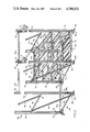
- FIG. 1 is a fragmentary perpsective view of a storage rack system embodying the features of this invention
- FIG. 2 is a fragmentary perspective view on a much larger scale showing certain components of the rack system in greater detail;
- FIG. 3 is an exploded fragmentary perspective view on a still larger scale illustrating the connections between the pallet bars and sway braces and the vertical frames of the FIG. 1 system;
- FIG. 4 is a fragmentary perspective view on an even larger scale illustrating the mode of adjustably mounting the gravity flow shelf units of the FIG. 1 system to the vertical frames thereof.
- FIG. 1 of the drawings shows a typical storage rack system 10 made in accordance with this invention and having a layout that might be used in a warehouse, for example.
- System 10 is composed of a number of knock-down rack assemblies 12 arranged in parallel rows R 1 , R 2 , etc. separated by aisles A 1 , A 2 , etc.
- the assemblies 12 are shown as being only two units or bays long. In actual practice, there woul be many bays in each assembly.
- the rack assemblies 12 may all be situated at floor level or, as shown in FIG. 1, they may extend up more than one level depending upon the height of the building in which the system is located and the requirements of the user.
- demountable bridge trusses or girders 16 are spaced along each aisle with their opposite ends removably connected to the rack assemblies 12 on opposite sides of the aisle, usually at a normal ceiling height, e.g. 9 feet.
- Floor joists 17 are suspended by saddle brackets 17a from these trusses and a deck 18, composed of plywood panels, for example, is laid down on the joists to define each level or mezzanine above the floor.
- each deck 18 is extended beyond the ends of the rows of rack assemblies so that personnel can walk from one aisle to the other on the upper levels of the system.
- the deck extension (not shown) is supported by additional trusses 16 suspended from vertical columns (not shown) extending down to the floor beyond the end of each rack assembly 12.
- Access to each upper level or mezzanine is had by a staircase 22 whose upper end is removably coupled to a suitable beam (not shown) supported by adjacent trusses 16.
- the staircase 22 is a welded-together unit having steps 22a and a side railing 22b and its lower end rests on the floor or the next lower level of the system 10.
- horizontal beams or railings 24 are removably coupled between the rack assemblies 12 at the beginnings of the aisles. Similar railings 24 extend between the upper ends of the columns supporting the deck extension beyond the ends of the aisles.
- row R 1 contains a pallet storage rack assembly 12a commonly used for reserve storage to support pallets P loaded with cartons C of stock being warehoused.
- the assembly 12a extends from the ground to the top of system 10.
- Row R 2 contains a gravity flow rack assembly 12b that also extends from the floor to the top of the system. That is, the cases C stored in the assembly 12b automatically feed to the front of the assembly so that fresh stock is accessible to the stockmen moving up and down aisle A 2 .
- This type assembly is most suitable for picking full cases or cartons C or for picking small stock or merchandise from open cases C stored therein.
- the row R 1 rack assembly may contain reserve storage to enable stockpersons moving along aisle A 1 to restock the gravity-flow rack assemblies 12b in row R 2 from the back so that such activity does not interfere with the picking and order filling being carried out in aisle A 2 .
- rack assembly 12a comprises a series of three vertical frames shown generally at 32 which support a series of vertically spaced horizontal pallet bars 33 at the front and rear of each bay. In some rack assemblies 12a, the lowest pallet bars 33 are omitted so that the loaded pallets P rest on the floor.
- Each vertical frame 32 shown in FIG. 1 and in greated detail in FIG. 2 includes a pair of spaced-apart support columns 34 rigidly connected by a series of vertically spaced horizontal beams 36, in the form of box girders whose opposite ends are welded to columns 34.
- the lowest beam 36 of each frame is spaced somewhat above the lower ends of the associated columns 34.
- each vertical frame includes diagonal box-frame-type braces 38 between adjacent beams 36 whose opposite ends are welded to those beams.
- the braces are connected at locations 40 offset or spaced inward along the beams from the beam connections to the columns a unique distance for each size rack frame 32.
- These eccentric connections produce a vertical frame structure which, instead of being a stiff truss, constitutes a moment-resisting eccentric braced frame which can experience bending deformation even to a limited extent in the plastic range beyond its elastic limit. This allows the rack assembly to survive horizontal inertial loads imposed upon it due to building vibrations, earthquakes and the like even though it is supporting very heavy gravity loads, e.g. 2000 pounds per pallet P.
- the illustrated rack assembly 12a is about forty inches deep, i.e. beams 36 are forty inches long.
- the beams are spaced about four and one half feet apart along the frame columns 34 and the diagonal braces 38 are connected to those beams at locations 40 spaced approximately five inches from the columns.
- the beams 36 could be longer or shorter giving the support frames 32, and the assembly 12a as a whole, more or less depth depending upon the particular installation. Whatever the depth, the spacing between beams 36 remains about the same, but the spacing or offset between the brace locations 40 and columns 34 will vary. For example, in an assembly whose frames 22 are about eighty-eight inches deep, the brace offset is slightly less than ten inches.
- the illustrated moment-resisting eccentric braced frames 32 which comprises assembly 12a are much better able to withstand horizontal inertial loads than the relatively stiff trusses formerly used as the vertical frames in prior racks of this general type as typified by the one disclosed in U.S. Pat. No. 3,900,112 mentioned above.
- each vertical frame 32 rests on a pair of footplates 42 removably connected to the lower open ends of the two frame columns 34 by fingers 43 struck from the plates and which project into the columns and resiliently engage their walls.
- the footplates 42 may be firmly anchored to the floor of the warehouse or other building, appropriate bolt openings 44 being provided in the plates for that purpose. Since the plates 42 are removable, the vertical frames 32 can be stacked close together when transporting the system 10 to the installation site, thus saving space for other components of the system. Also, since the ends of the columns 34 are open, they are easily field-spliced without tools to make longer columns if that is required for a particular system 10.
- each bar 33 comprising assembly 12a extend between adjacent vertical frames 32 at the front and back of the assembly and each front and rear bar pair may be located at any height on the frames as shown in FIG. 1.
- Each bar is composed of two mating sections 33a and 33b which snap together to form a box girder.
- Each bar section 33a is a generally rectangular cold roll-formed metal channel having a front wall 46a and top and bottom walls 46b and 46c respectively, the top wall rear edge margin 46d being turned downward.
- the channel bottom wall 46c extends rearwardly beyond top wall 46b and its rear edge margin 46e is bent upward.
- a longitudinal groove 47a is formed in the channel front wall 46a about one-third of the way down on that wall and the free edge of wall margin 46e is also grooved to form an inside rib 47b.
- the other pallet bar section 33b is also a cold roll-formed metal channel. It is formed with a vertical rear wall 48a and a horizontal forwardly-extending top wall 48b whose leading edge margin is turned down to form a vertical front wall 48c.
- the lower edge margin of wall 48a is turned rearward to form a ledge 48d and then downwardly again to form an extended rear wall 48e.
- the channel extends forwardly below wall 48e to form a bottom wall 48f whose front edge margin is turned upwards to create a longitudinal upwardly-extending lip 48g.
- the free edge of front wall 48c is grooved to form an inside longitudinal rib 49a and a groove 49b extends along channel wall 48e midway between its upper and lower edges.
- the bar section 33b is shaped to cooperate with bar section 33a so that its top and front walls engage around the top and front walls of section 33a and so that its extended rear and bottom walls engage inside the rear and bottom walls of section 33a.
- the rib 49a of section 33b snaps into groove 47a in section 33a
- the rib 47b of section 33a snaps into the grove 49b in section 33b thereby locking those two channel parts together.
- the tolerances and interferences of the two bar sections are such that, when they are snapped together as shown, it is practically impossible to separate them.
- the two parts each of which is a formed channel of uniform wall thickness, cooperate to form a very rigid box girder having double wall thickness only at those locations where needed at the bottom and top of the bar where the stress caused by a vertical load is a maximum. Therefore, the bar is well able to support very heavy pallet loads without buckling or excessive deflection; yet its material cost is kept to a minimum.
- each pallet bar 33 is connected to the adjacent frame columns 34 by special releasable connector assemblies shown generally at 50.
- Each connector assembly 50 in conjunction with the column 34 structure, achieves a very high degree of fixity between the connected-together pallet bar and column.
- FIG. 3 of the drawings shows the column 34 and connector assembly 50 in detail.
- each column is a preblanked cold roll-formed metal part having the general shape of a hollow I-beam which is symmetrical about its longitudinal or vertical axis. That is, the column has a flat front wall 52 as well as a parallel rear wall 54 composed of two longitudinal sections 54a and 54b having opposing inturned edge margins 54c secured together by a series of vertically spaced welds 55.
- Each column also has a side wall 56 formed with front and rear truncated flanges 58 and 62 respectively.
- the column is completed by a second side wall 64 formed with front and rear flanges 66 and 68 respectively.
- the opposing flange walls 58a and 66a at the front of the column converge, as do the corresponding flange walls 62a and 68a at the rear of the column.
- the flange wall pairs 58a, 62a and 66a, 68a at the opposite sides of the column each define planes which intersect along an imaginary line inside the column.
- Two series of vertically spaced-apart vertical framing slots 72 and 74 are formed at the opposite sides of the column front wall 52 adjacent flanges 58 and 66 respectively.
- Two series of similar slots 76 and 78 are located in the column rear wall 54 adjacent flanges 62 and 68, the corresponding slots in the four series all being located at the same heights on the column, say every two inches.
- Additional series of vertically spaced, smaller slit-type vertical slots are present in the column side walls 54 and 64. More particularly, as best seen in FIG.
- a series of vertical slots 82a is formed in column wall 56 adjacent flange 58 and a second parallel column of slots 82b are located in that same wall adjacent flange 62, the two series of slots being vertically offset or staggered.
- located and offset series of slots 84a and 84b are provided in the column side wall 64.
- each such connection is designed to provide a fixed, moment connection to resist combinations of vertical loading and/or lateral loading where the latter loading can be either in the aisle-wise direction or the front-to-back direction.
- each pallet bar 33 is mirror images of one another.
- Each comprises an elongated channel-shaped stamped metal connector 92 whose cross section has the general shape of the letter J.
- the connector has a long limb 92a butt welded to the ends of pallet bar sections 33a and 33b making it impossible to separate those sections and further increasing the stiffness and strength of the pallet bar 33 as a whole.
- Each connector 92 further includes a wedge-shaped front portion 92b which curves or angles away from limb 92a and a short limb 92c which extends rearwardly from portoin 92b, being spaced generally parallel to limb 92a.
- a series of three vertically spaced, downwardly open hooks 94 are formed at the rear edge of connector limb 92a and a second series of three vertically spaced, downwardly open hooks 96 are present at the rear edge of connector limb 92c, the uppermost hooks in the two series being located right at the top of the connector and ther other corresponding hooks in the two series being positioned at the same heights on the connector.
- the hooks 96 are shaped and arranged so that they can hook into vertically adjacent slots 74 or 76 in the front or rear wall of column 34.
- the remaining component of the connector assembly 50 is a connector lock 102 best seen in FIG. 3 to be an elongated stamped metal part formed as an L-shaped section with approximately equal legs.
- One leg 102a of the lock is formed with a series of three vertically spaced vertical slots 104, the uppermost slot being an open slot extending to the upper edge of the connector lock.
- the other lock leg 102b is provided with a series of three vertically spaced downwardly open hooks 106.
- the hooks 106 are located more or less at the same heights on the connector lock as the slots 104 with their lower ends extending somewhat below the lower ends of those slots. These hooks are also shaped and positioned so that they can hook into vertically adjacent slots 72 or 78 in the front or rear wall of column 34.
- the connector lock 102 is first engaged to the column at the location on the column where the connection is to be made. Assume, for example, that the right-hand end of a pallet bar 33 is being connected to the front center column 34 of the rack assembly 12a illustrated in FIG. 1. In this event, first the connector lock 102 shown at the right-hand side of FIG. 3 is positioned at the appropriate height on the column and its hooks 106 are hooked into the three closest slots 78 in the rear wall of the column.
- the openings under hooks 106 are more or less vertical so that the hooks rest on the lower edges of slots 78, with the lock engaging snugly around column flange 68 so that its leg 102a, including the slots 104 therein, extend beyond the column side wall 64.
- the connector 92 is positioned opposite lock 102 with its limb 92a engaged flush against the column side wall 64.
- the connector is then slid rearwardly toward column flange 66 so that its hooks 96 project into the three nearest slots 74 in the column front wall, while at the same time its hooks 94 engage in the slots 104 of the connector lock.
- the connector portion 92b is curved or wedge shaped and the column flange 66 with its convergent wall 66a is truncated. Therefore, as the connector hooks 94 and 96 are pressed further into their respective slots 104 and 74, the connector portion 92b is urged ever more firmly against against the flange 66. That engagement, in turn, causes the convergent flange wall 66a to wedge the connector limb 92a very tightly against the column side wall 64 over the entire height of the connector.
- outboard walls 104a of the connector lock slots 104 are downwardly-inwardly tapered or slanted so that, as the connector hooks 94 are urged downwardly into those slots, they are wedged toward the column side wall 64 thereby drawing the rear edge margin of connector limb 92a tightly against the column sidewall 64 along the entire height of the connector.
- the connector assembly 50 described herein clamps the column between connector 92 and lock 102 so that the pallet bar cannot rotate up and down or fore and aft relative to the column. Nor can the bar rotate about its own longitudinal axis.
- the aforesaid clamping action draws the connector 92 at the end of the bar very firmly against the side wall of the column, thereby preventing vertical as well as fore and aft translations of the end of the pallet bar 33 relative to the column. Therefore, the rack assembly 12a with its pallet bars 33 connected to its vertical frame columns with this high degree of fixity can withstand normal gravity loads due to the product stored thereon--as well as vertical inertial loads caused, for example, by the dropping of loaded pallets on the pallet bars. Further, the rack assembly has little tendency to sway or deform even when strong horizontal or lateral inertial forces, as might be caused by building vibrations or strong earth tremors, are applied to the upper regions of the assembly.
- assembly 50 does not impose excessive localized stresses to the column as might cause its walls to bend or tear. Rather, assembly 50 achieves its very strong clamping connection to the column and its high degree of fixity primarily due to the hooking-wedging connection between connector 92 and its lock 102.
- Those members are heavy gauge cold roll-formed metal parts which are well able to withstand localized stresses imposed on them due to their interconnection.
- the clamping engagement of those members to the walls of the column occurs over a relatively large surface area around the flanged side wall of the column.
- the connector assembly 50 does firmly connect the end of each pallet bar 33 to the adjacent column 34, achieving a joint with a very high degree of fixity, the assembly can be uncoupled or disconnected from the column very easily in the event that is required to relocate the bars or to dismantle the rack assembly. Furthermore, this can be done without any special tools; it simply requires an upward blow from a board or hammer against the end of the particular bar 33. This lifts the connector and lock hooks 94 and 106 from their seats in column slots 74 and 78 sufficiently to release the clamp. The end of the bar can then be lifted up sufficiently to permit the connector hooks 94 and 96 to be withdrawn from their respective slots 104 and 74, thereby disconnecting the end of the bar from the column. The connector lock 102 can then be removed from the column by lifting it sufficiently to permit its hooks 106 to be withdrawn from the slots 78 in the column.
- a generally rectangular sheet metal keeper clip 107 is attached at one end by spot welds 108 to connector lock 102 so that the clip covers the middle slot 104 and part of the lowest slot 104.
- Each clip has a rectangular slot 107a punched out in register with the middle lock slot 104, with the punched-out metal being bent down to form a small clip handle 107b. Below the handle, the clip is bent to form a longitudinal rib 107c which projects into the lowest lock slot 104 as shown.
- the connector hooks 94 extend through the lock slots 104 as shown in dotted lines in FIG. 3.
- the middle hook 94 projects through clip slot 107a and the lowest hook 94 pushes the lower, free end of the clip away from the lock 102 until that hook clears the lower edge of its slot 104. At that point, the hook can be moved down in that slot until it clears the lower edge of the clip.
- the clip being resilient, snaps back against lock 102 so that its rib 107c engages in the portion of slot 104 above hook 94 as shown in FIG. 3. In that position, the clip rib acts as a short rigid column preventing upward movement of the connector 92 relative to the lock 102.
- clip 107 is bowed or arched as shown so that it has some lengthwise compliance. In this way, if the connection assembly is subjected to an unusually heavy load, so that an upward force is applied to the lower edge of the clip by the lowest hook 94, the clip will flex rather than break away from lock 102 at its welds 108.
- the connector assembly 50 at the left-hand end of bar 33, shown at the left in FIG. 3, is a mirror image of the one at the right-hand end just described and it functions in exactly the same way to releasably couple the left-hand end of a pallet bar to the right side of the adjacent column 34.
- each column is essentially symmetrical about its vertical or longitudinal axis, with a given pair of connector assemblies 50, connections can be made to both sides of a column at the front or rear of the column.
- connection assemblies 50 may be used to connect the ends of trusses 16 shown in FIG. 1 and the beam that supports the upper end of staircase 22 to columns 34. Since assemblies 50 can attach bars 33 right at the tops of columns 34, a continuous flat deck D can be provided all along the top of rack assembly 12a as shown in FIG. 1.
- assembly 12b also comprises spaced-apart vertical frames 32.
- the frames are maintained in spaced relation by horizontal sway braces. Since these members are not exposed to heavy vertical loads as are the pallet bars, they do not have to be as resistant to bending.
- one of the sections used to form the pallet bar 33 namely section 33a, is used also for the sway brace.
- such sway braces 33a are connected between the lower ends of adjacent columns 34 at the rear of the assembly.
- the vertical frames 32 support a series of vertically spaced-apart gravity-flow shelf units 109 in each bay of rack assembly 12b.
- the shelf units are typically about sixty inches deep or long.
- the vertical frames might be eighty-eight inches deep to support shelf units that are about one hundred twenty inches long.
- Each shelf unit is composed of front and rear transverse frame members 110 and 112 respectively and opposite, mirror-image side members 114 joined at their ends to form a rectangular frame.
- Cross members 118 are connected between the vertical webs of side members 114 to strengthen the shelf unit.
- a series of laterally spaced-apart gravity-feed roller tracks 122 are supported at their opposite ends from the front and rear frame members 110 and 112 of each shelf unit.
- the illustrated tracks are substantially the same as the ones disclosed in the aforementioned U.S. Pat. No. 3,900,112 and connect to the front and rear frame members of the shelf unit in the same way described there.
- each shelf frame side member 114 is turned inward beyond 90° to form a relatively wide ledge 114a which inclines from the side of the web so that only its outer edge engages the underside of cross members 118. Also, a narrow edge margin of that ledge is bent down to form a lip or flange 114b which makes an obtuse angle with ledge 114a.
- the upper edge margin of the vertical web of each side member 114 is also turned inward over ledge 114a to form a rib or flange 114c. These flanges at the upper and lower edges of side member 114 rigidify that member.
- Transverse slots 116 are spaced apart along each member ledge 114a for a distance of about twenty inches from the front frame member 110. These slots are used to adjustably suspend the shelf units 109 from columns 34 as will be described presently.
- each shelf unit is suspended by way of its side members 114 from the four columns 34 defining the rack assembly bay in which the shelf unit is located.
- special hanger clips 124 are utilized to adjustably support the shelf unit side members from the columns.
- Each clip 124 is a small, low profile, rigid, stamped metal part whose thickness is slightly less than the width of the slots 82a, 82b, 84a and 84b in the side walls of column 34. It has a generally ovular shape with an upwardly-forwardly extending finger 126 at the rear of the clip which terminates in a flat, generally vertical end wall 126a.
- a tab 128 Spaced slightly forwardly of and below wall 126a is a tab 128 which extends laterally to one side of the clip.
- a similar tap 132 at the bottom of the clip directly below tab 128 extends laterally in the opposite direction from tab 128.
- a small vertical wedge-shaped notch 134 is present at the bottom of the clip just forwardly of tab 132 and the mouth of that notch, as well as the spacing between finger wall 126a and tab 128, are slightly larger than the thickness of the column side walls 56 and 64.
- the clip 124 is further formed with a nose 136 which projects upward just forward of tab 128 more or less to the same height as finger 126.
- Each clip 124 is arranged and adapted so that its rear edge margin, including finger 126, can be inserted into a slot 82a, 82b, 84a or 84b in column 34 until the tabs 128 and 134 engage the relevant column side wall as shown in dotted lines in FIG. 4.
- the clip is then free to slide downward in the slot until the lower edge of the slot wedges into the clip notch 134.
- the clip is free to cock or tilt outward on the slot lower edge until the finger wall 126a engages the inside surface of the column side wall.
- lateral cocking or swinging motions of the clip are inhibited by the engagement of the clip fingers 128 and 132 against the column side wall on opposite sides of the slot.
- the clip is thus connected very securely to the column; yet it can be removed easily simply by lifting the clip sufficiently to withdraw the slot edge from the clip notch 134 and then withdrawing the clip from the slot.
- the clip 124 attached as aforesaid to column 34 is adapted to support one end of a shelf unit side member 114. Consequently, four clips are positioned on the four columns 34 supporting the particular shelf unit at the heights on those columns that will give the shelf unit the desired front-to-back incline.
- the shelf unit is positioned in the rack bay so that its side member ledges 114a rest on the four clips. Then the front of the shelf unit is lifted slightly and the unit slid on the rear clips forwards or backwards relative to vertical frames 32 until the unit projects the desired distance from the fronts of those frames. Finally, the front end of the unit is lowered so that the front pair of clips engage in the nearest ledge slots 116 thereby fixing that fore and aft position of the shelf unit.
- the side member ledges 114a are inclined. Therefore, the reaction force of the clips against that weighted surface wedges the vertical web of the side member tightly against the column side wall. Also, the edge of that member, i.e. the portion of ledge 114a inboard of an engaged-in slot 116 at the front of the shelf unit rests on the engaging clip tab 128. Therefore, downward forces are distributed over the opposing surfaces of that ledge and tab so that there is little tendency for the plate to tear adjacent to a slot 116 at the front of the shelf unit when the unit is subjected to a vertical load. Still further, the ledge slots 116 are made slightly wider than the clip nose 136 to permit the shelves to be supported by the columns at various front to rear inclinations.
- the ledge lip 114b on each side member 114 is angled outwardly as described so that the shelf units 109 will nest when stacked to facilitate the storage, shipping and handling of the shelf units. That is, the ledges 114a and their lips 114b will engage on and interfit with the upper flange 114c of the underlying shelf unit in the stack to stabilize the stack.
- each shelf unit 109 can be adjustly positioned heightwise in the rack assembly 12b, at any desired angle of inclination, so too can it be adjustably positioned in the fore and aft direction in the assembly. This simply involves lifting the front of the shelf unit slightly and moving it fore or aft within the rack bay to the right position and then lowering the front end so that the clips 124 engage in the desired side plate ledge slots 116.
- scales are inscribed on the inside faces of the vertical webs of the side members 114 as shown at 144 in FIG. 4. This insures that the clips on opposite sides of the shelf unit will be engaged in corresponding slots 116 so that the shelf unit is supported in a squared-up condition.
- the shelf units of a given rack assembly 12b may be positioned directly above one another in a "squarefront" arrangement as shown in FIG. 2 or the shelf units may be "layback" as shown in FIG. 1 to afford easier access to cartons C and totes supported on the shelf units because the tops of the cartons and totes are exposed making it easier to pick articles from the cartons and totes.
- the "profiling" of the shelf units in the rack assembly 12b as described can be accomplished without any tools or field measurements.
- Each locking clp is a formed spring-metal part having a relatively wide head portion 146a and a tail portion 146b formed as a barb which can snap into a slot 82a, 82b, 84a or 84b just above the top of the shelf unit side member 114.
- the clip is removed from the slot by squeezing the opposite sides of the head portion 146a together. This bends and narrows tail portion 146b sufficiently to permit its withdrawal from the slot.
Abstract
Description
Claims (21)
Priority Applications (1)
| Application Number | Priority Date | Filing Date | Title |
|---|---|---|---|
| US06/867,897 US4708252A (en) | 1983-12-16 | 1986-05-20 | Storage rack system |
Applications Claiming Priority (2)
| Application Number | Priority Date | Filing Date | Title |
|---|---|---|---|
| US56227983A | 1983-12-16 | 1983-12-16 | |
| US06/867,897 US4708252A (en) | 1983-12-16 | 1986-05-20 | Storage rack system |
Related Parent Applications (1)
| Application Number | Title | Priority Date | Filing Date |
|---|---|---|---|
| US06769994 Continuation | 1985-08-26 |
Publications (1)
| Publication Number | Publication Date |
|---|---|
| US4708252A true US4708252A (en) | 1987-11-24 |
Family
ID=27072899
Family Applications (1)
| Application Number | Title | Priority Date | Filing Date |
|---|---|---|---|
| US06/867,897 Expired - Fee Related US4708252A (en) | 1983-12-16 | 1986-05-20 | Storage rack system |
Country Status (1)
| Country | Link |
|---|---|
| US (1) | US4708252A (en) |
Cited By (37)
| Publication number | Priority date | Publication date | Assignee | Title |
|---|---|---|---|---|
| US5181815A (en) * | 1990-11-01 | 1993-01-26 | Haberkorn Robert W | Collapsible structure for unitizing and bracing a load in a trailer |
| US5313891A (en) * | 1991-12-16 | 1994-05-24 | The Mead Corporation | Beverage aisle unit |
| US5368174A (en) * | 1992-08-07 | 1994-11-29 | Unr Industries, Inc. | Storage rack beam having surface enabling indicia at high or low elevation to be easily read |
| US5439280A (en) * | 1993-07-09 | 1995-08-08 | Keller Products Incorporated | File hanger system and clips therefor |
| US5975318A (en) * | 1998-02-13 | 1999-11-02 | Display Technologies, Inc. | Display shelf assembly and bracket useful therein |
| US6185899B1 (en) * | 1996-03-05 | 2001-02-13 | Christopher D. De Niet | Metal panel structures |
| US6223916B1 (en) * | 1998-07-03 | 2001-05-01 | Barry M. Enos | Shelving crossbar retainer and assembly and method for fixing a crossbar to a post |
| US6298537B1 (en) * | 1998-03-13 | 2001-10-09 | Dany Dion | Pallet rack repair system |
| US6352164B1 (en) | 1999-07-20 | 2002-03-05 | Paltier, L.L.C. | Storage rack having locking beam-to-column connection |
| US6497033B1 (en) * | 2000-02-22 | 2002-12-24 | Robert S. Agar | Method of making a shelving standard |
| US6722291B2 (en) | 2002-03-19 | 2004-04-20 | Slooters, Inc. | Separation members for selective placement between sheet members oriented horizontally and stacked vertically and method of usage thereof |
| US20040200794A1 (en) * | 2001-07-30 | 2004-10-14 | De Rijk Hugo Casper Johan | Rack |
| WO2004089159A1 (en) * | 2003-04-14 | 2004-10-21 | Cheon Soon Choi | Prefabricating rack frame |
| US6814245B2 (en) | 2002-10-09 | 2004-11-09 | Montel Inc. | Hybrid shelving unit |
| US20040245414A1 (en) * | 2003-03-31 | 2004-12-09 | Roland Boltz | Perforated section supporting device adapted to be fixed to a surface such as a ceiling |
| US20050035340A1 (en) * | 2003-08-14 | 2005-02-17 | Otte Donald R. | Protective railing mounting arrangement |
| US20070042638A1 (en) * | 2003-04-14 | 2007-02-22 | Choi Cheon S | Prefabricating rack frame |
| US7464509B1 (en) * | 2005-07-15 | 2008-12-16 | Brown James C | Security wall |
| US20100089699A1 (en) * | 2008-10-15 | 2010-04-15 | Meltz George R | System and apparatus for supportive scaffolding |
| US20100181274A1 (en) * | 2009-01-20 | 2010-07-22 | Vargo William R | Demountable shelving unit |
| US7896177B1 (en) * | 2008-05-08 | 2011-03-01 | Toma Dennis R | Versatile support system and methods thereof |
| US20110064547A1 (en) * | 2009-09-11 | 2011-03-17 | Krones Ag | Apparatus and method for loading a pack storing device |
| US20120111808A1 (en) * | 2010-05-26 | 2012-05-10 | Irega Ag | Knockdown shelving system for storing vehicle wheel sets |
| US20130068705A1 (en) * | 2011-06-23 | 2013-03-21 | Glidestore Freetrack Pty Ltd | Upright support configuration for a pallet racking system |
| CN105686389A (en) * | 2016-01-29 | 2016-06-22 | 杭州巨象物流设备有限公司 | Goods shelf |
| EP3034168A1 (en) * | 2014-12-16 | 2016-06-22 | Binder GmbH | Internal boiler of a simulation cabinet and simulation cabinet with an internal boiler |
| US10035030B2 (en) * | 2016-03-04 | 2018-07-31 | Firebird Sprinkler Company Llc | Water collecting pallet rack and method of fire protection |
| RU2669639C2 (en) * | 2014-12-16 | 2018-10-12 | Биндер Гмбх | Inner chamber of test cabinet and test cabinet with inner chamber |
| RU2686191C1 (en) * | 2017-07-21 | 2019-04-24 | Биндер Гмбх | Method for accuracy positioning to position of internal housing in climatic cabinet external housing and climatic cabinet |
| US10688496B2 (en) | 2014-12-16 | 2020-06-23 | Binder Gmbh | Simulation cabinet |
| USD910958S1 (en) * | 2019-03-12 | 2021-02-16 | Craig Richard Hokanson | Cantilever rack with backset braces |
| US11011893B2 (en) * | 2019-01-16 | 2021-05-18 | General Electric Technology Gmbh | Seismic support structure |
| US11105088B2 (en) * | 2017-08-18 | 2021-08-31 | Knauf Gips Kg | Modular system for creating a structure, module connector and structure comprising a modular system |
| US11363883B2 (en) * | 2018-02-08 | 2022-06-21 | Alert Innovation Inc. | Modular structure for an automated storage and retrieval system |
| US20220312965A1 (en) * | 2021-04-06 | 2022-10-06 | DriFlower, LLC | Vegetation hanging and drying system and brackets thereof |
| US11686107B2 (en) * | 2020-09-27 | 2023-06-27 | Pipp Mobile Storage Systems, Inc. | Configurable scaffolding system |
| US20240041202A1 (en) * | 2020-05-14 | 2024-02-08 | Hangzhou Great Star Industrial Co., Ltd. | Industrial rack |
Citations (24)
| Publication number | Priority date | Publication date | Assignee | Title |
|---|---|---|---|---|
| US1952111A (en) * | 1931-07-31 | 1934-03-27 | Lyon Metal Products Inc | Shelving construction |
| US2266206A (en) * | 1941-01-24 | 1941-12-16 | Hartley H Jackson | Adjustable cantilever bracket |
| US2937767A (en) * | 1958-12-15 | 1960-05-24 | Unistrut Products Company | Shelving structure |
| US2963170A (en) * | 1959-04-28 | 1960-12-06 | Karl Steiner Fa | Shelf rack |
| US3009582A (en) * | 1958-09-08 | 1961-11-21 | American Metal Prod | Storage rack |
| US3332197A (en) * | 1964-06-30 | 1967-07-25 | James L Hinkle | Interlocked structural assemblies and stiffeners therefor |
| FR1522501A (en) * | 1967-03-16 | 1968-04-26 | Strasbourg Forges | Shelving |
| US3456970A (en) * | 1966-09-06 | 1969-07-22 | Dexion Ltd | Connections between structural components |
| US3520507A (en) * | 1968-06-21 | 1970-07-14 | Palmer Shile Co | Removable foot for adjustable storage rack |
| US3545626A (en) * | 1968-05-10 | 1970-12-08 | Edward Seiz | Storage structure |
| US3562992A (en) * | 1968-11-29 | 1971-02-16 | Lewis R Kinsey | Building structural element |
| US3606027A (en) * | 1968-05-14 | 1971-09-20 | Westeel Rosco Ltd | Adjustable storage rack |
| US3611666A (en) * | 1970-03-10 | 1971-10-12 | Republic Steel Corp | Sheet metal box beam |
| US3726414A (en) * | 1971-06-28 | 1973-04-10 | Speedrack Inc | Storage rack and beam for use therein |
| US3871525A (en) * | 1973-04-23 | 1975-03-18 | Unarco Industries | Safety connector for knock-down racks |
| US3900112A (en) * | 1973-04-09 | 1975-08-19 | Kingston Warren Corp | Gravity storage system |
| US3999875A (en) * | 1973-01-12 | 1976-12-28 | Mavil S.A.-Z.A.I. | Upright and cross-piece assembly for collapsible racking or the like |
| US4002000A (en) * | 1975-06-30 | 1977-01-11 | Palmer-Shile Company | Beam construction and method of manufacture |
| US4038802A (en) * | 1976-05-17 | 1977-08-02 | Questor Corporation | Tubular spindle cover |
| US4064996A (en) * | 1975-12-17 | 1977-12-27 | Robert L. Shillum | Rack system |
| US4069638A (en) * | 1974-06-05 | 1978-01-24 | Scanovator Ab | Structure of lightweight bars and connector means therefore |
| US4173934A (en) * | 1976-09-24 | 1979-11-13 | Speedshelf International, Inc. | Shelving structure |
| US4349171A (en) * | 1980-09-22 | 1982-09-14 | Nestier Corporation | Shelf mounting bracket for storage rack |
| US4372451A (en) * | 1980-06-26 | 1983-02-08 | Interlake, Inc. | Gravity-feed storage and delivery system |
-
1986
- 1986-05-20 US US06/867,897 patent/US4708252A/en not_active Expired - Fee Related
Patent Citations (24)
| Publication number | Priority date | Publication date | Assignee | Title |
|---|---|---|---|---|
| US1952111A (en) * | 1931-07-31 | 1934-03-27 | Lyon Metal Products Inc | Shelving construction |
| US2266206A (en) * | 1941-01-24 | 1941-12-16 | Hartley H Jackson | Adjustable cantilever bracket |
| US3009582A (en) * | 1958-09-08 | 1961-11-21 | American Metal Prod | Storage rack |
| US2937767A (en) * | 1958-12-15 | 1960-05-24 | Unistrut Products Company | Shelving structure |
| US2963170A (en) * | 1959-04-28 | 1960-12-06 | Karl Steiner Fa | Shelf rack |
| US3332197A (en) * | 1964-06-30 | 1967-07-25 | James L Hinkle | Interlocked structural assemblies and stiffeners therefor |
| US3456970A (en) * | 1966-09-06 | 1969-07-22 | Dexion Ltd | Connections between structural components |
| FR1522501A (en) * | 1967-03-16 | 1968-04-26 | Strasbourg Forges | Shelving |
| US3545626A (en) * | 1968-05-10 | 1970-12-08 | Edward Seiz | Storage structure |
| US3606027A (en) * | 1968-05-14 | 1971-09-20 | Westeel Rosco Ltd | Adjustable storage rack |
| US3520507A (en) * | 1968-06-21 | 1970-07-14 | Palmer Shile Co | Removable foot for adjustable storage rack |
| US3562992A (en) * | 1968-11-29 | 1971-02-16 | Lewis R Kinsey | Building structural element |
| US3611666A (en) * | 1970-03-10 | 1971-10-12 | Republic Steel Corp | Sheet metal box beam |
| US3726414A (en) * | 1971-06-28 | 1973-04-10 | Speedrack Inc | Storage rack and beam for use therein |
| US3999875A (en) * | 1973-01-12 | 1976-12-28 | Mavil S.A.-Z.A.I. | Upright and cross-piece assembly for collapsible racking or the like |
| US3900112A (en) * | 1973-04-09 | 1975-08-19 | Kingston Warren Corp | Gravity storage system |
| US3871525A (en) * | 1973-04-23 | 1975-03-18 | Unarco Industries | Safety connector for knock-down racks |
| US4069638A (en) * | 1974-06-05 | 1978-01-24 | Scanovator Ab | Structure of lightweight bars and connector means therefore |
| US4002000A (en) * | 1975-06-30 | 1977-01-11 | Palmer-Shile Company | Beam construction and method of manufacture |
| US4064996A (en) * | 1975-12-17 | 1977-12-27 | Robert L. Shillum | Rack system |
| US4038802A (en) * | 1976-05-17 | 1977-08-02 | Questor Corporation | Tubular spindle cover |
| US4173934A (en) * | 1976-09-24 | 1979-11-13 | Speedshelf International, Inc. | Shelving structure |
| US4372451A (en) * | 1980-06-26 | 1983-02-08 | Interlake, Inc. | Gravity-feed storage and delivery system |
| US4349171A (en) * | 1980-09-22 | 1982-09-14 | Nestier Corporation | Shelf mounting bracket for storage rack |
Cited By (51)
| Publication number | Priority date | Publication date | Assignee | Title |
|---|---|---|---|---|
| US5181815A (en) * | 1990-11-01 | 1993-01-26 | Haberkorn Robert W | Collapsible structure for unitizing and bracing a load in a trailer |
| US5313891A (en) * | 1991-12-16 | 1994-05-24 | The Mead Corporation | Beverage aisle unit |
| US5368174A (en) * | 1992-08-07 | 1994-11-29 | Unr Industries, Inc. | Storage rack beam having surface enabling indicia at high or low elevation to be easily read |
| US5386917A (en) * | 1992-08-07 | 1995-02-07 | Unr Industries, Inc. | Storage rack system with fire extinguishing device |
| US5492231A (en) * | 1992-08-07 | 1996-02-20 | Unarco Material Handling, Inc. | Storage rack having support seam with outer, generally arcuate, indicia-receiving surface |
| US5526945A (en) * | 1992-08-07 | 1996-06-18 | Unarco Material Handling, Inc. | Storage rack having support beam with channel profile and inclinded surface |
| US5655675A (en) * | 1992-08-07 | 1997-08-12 | Unarco Material Handling, Inc. | Storage rack system with fire extinguishing device |
| US5749482A (en) * | 1992-08-07 | 1998-05-12 | Unarco Material Handling, Inc. | Storage rack beam having surface enabling indicia at low elevation to be easily read |
| US5439280A (en) * | 1993-07-09 | 1995-08-08 | Keller Products Incorporated | File hanger system and clips therefor |
| US6185899B1 (en) * | 1996-03-05 | 2001-02-13 | Christopher D. De Niet | Metal panel structures |
| US5975318A (en) * | 1998-02-13 | 1999-11-02 | Display Technologies, Inc. | Display shelf assembly and bracket useful therein |
| US6298537B1 (en) * | 1998-03-13 | 2001-10-09 | Dany Dion | Pallet rack repair system |
| US6223916B1 (en) * | 1998-07-03 | 2001-05-01 | Barry M. Enos | Shelving crossbar retainer and assembly and method for fixing a crossbar to a post |
| US6352164B1 (en) | 1999-07-20 | 2002-03-05 | Paltier, L.L.C. | Storage rack having locking beam-to-column connection |
| US6497033B1 (en) * | 2000-02-22 | 2002-12-24 | Robert S. Agar | Method of making a shelving standard |
| US7191908B2 (en) * | 2001-07-30 | 2007-03-20 | Hugo Johan Casper De Rijk | Rack with uprights and girders with couplers facing the uprights, and system and method for producing same |
| US20040200794A1 (en) * | 2001-07-30 | 2004-10-14 | De Rijk Hugo Casper Johan | Rack |
| US6722291B2 (en) | 2002-03-19 | 2004-04-20 | Slooters, Inc. | Separation members for selective placement between sheet members oriented horizontally and stacked vertically and method of usage thereof |
| US6814245B2 (en) | 2002-10-09 | 2004-11-09 | Montel Inc. | Hybrid shelving unit |
| US7387287B2 (en) * | 2003-03-31 | 2008-06-17 | I.C.M. Group | Perforated section supporting device adapted to be fixed to a surface such as a ceiling |
| US20040245414A1 (en) * | 2003-03-31 | 2004-12-09 | Roland Boltz | Perforated section supporting device adapted to be fixed to a surface such as a ceiling |
| US20070062898A1 (en) * | 2003-04-14 | 2007-03-22 | Teknoa Industrial Inc. | Prefabricating rack frame |
| WO2004089159A1 (en) * | 2003-04-14 | 2004-10-21 | Cheon Soon Choi | Prefabricating rack frame |
| US20070042638A1 (en) * | 2003-04-14 | 2007-02-22 | Choi Cheon S | Prefabricating rack frame |
| US20050035340A1 (en) * | 2003-08-14 | 2005-02-17 | Otte Donald R. | Protective railing mounting arrangement |
| US7464509B1 (en) * | 2005-07-15 | 2008-12-16 | Brown James C | Security wall |
| US7896177B1 (en) * | 2008-05-08 | 2011-03-01 | Toma Dennis R | Versatile support system and methods thereof |
| US20100089699A1 (en) * | 2008-10-15 | 2010-04-15 | Meltz George R | System and apparatus for supportive scaffolding |
| US8302788B2 (en) * | 2009-01-20 | 2012-11-06 | Hardy Imports, Inc. | Demountable shelving unit |
| US20100181274A1 (en) * | 2009-01-20 | 2010-07-22 | Vargo William R | Demountable shelving unit |
| EP2295347A3 (en) * | 2009-09-11 | 2013-12-11 | Krones AG | Method and device for loading a buffer rack with packages |
| US8721249B2 (en) * | 2009-09-11 | 2014-05-13 | Krones Ag | Apparatus and method for loading a pack storing device |
| US20110064547A1 (en) * | 2009-09-11 | 2011-03-17 | Krones Ag | Apparatus and method for loading a pack storing device |
| US8235224B2 (en) * | 2010-05-26 | 2012-08-07 | Irega Ag | Knockdown shelving system for storing vehicle wheel sets |
| US20120111808A1 (en) * | 2010-05-26 | 2012-05-10 | Irega Ag | Knockdown shelving system for storing vehicle wheel sets |
| US20130068705A1 (en) * | 2011-06-23 | 2013-03-21 | Glidestore Freetrack Pty Ltd | Upright support configuration for a pallet racking system |
| US10603663B2 (en) | 2014-12-16 | 2020-03-31 | Vega Grieshaber Kg | Interior vessel of a simulation cabinet and simulation cabinet with an interior vessel |
| EP3034168A1 (en) * | 2014-12-16 | 2016-06-22 | Binder GmbH | Internal boiler of a simulation cabinet and simulation cabinet with an internal boiler |
| US10688496B2 (en) | 2014-12-16 | 2020-06-23 | Binder Gmbh | Simulation cabinet |
| RU2669639C2 (en) * | 2014-12-16 | 2018-10-12 | Биндер Гмбх | Inner chamber of test cabinet and test cabinet with inner chamber |
| CN105686389A (en) * | 2016-01-29 | 2016-06-22 | 杭州巨象物流设备有限公司 | Goods shelf |
| US10035030B2 (en) * | 2016-03-04 | 2018-07-31 | Firebird Sprinkler Company Llc | Water collecting pallet rack and method of fire protection |
| RU2686191C1 (en) * | 2017-07-21 | 2019-04-24 | Биндер Гмбх | Method for accuracy positioning to position of internal housing in climatic cabinet external housing and climatic cabinet |
| US11226132B2 (en) | 2017-07-21 | 2022-01-18 | Binder Gmbh | Method for the precisely fitting positioning of an inner boiler in the outer boiler of an air-conditioning cabinet and air-conditioning cabinet |
| US11105088B2 (en) * | 2017-08-18 | 2021-08-31 | Knauf Gips Kg | Modular system for creating a structure, module connector and structure comprising a modular system |
| US11363883B2 (en) * | 2018-02-08 | 2022-06-21 | Alert Innovation Inc. | Modular structure for an automated storage and retrieval system |
| US11011893B2 (en) * | 2019-01-16 | 2021-05-18 | General Electric Technology Gmbh | Seismic support structure |
| USD910958S1 (en) * | 2019-03-12 | 2021-02-16 | Craig Richard Hokanson | Cantilever rack with backset braces |
| US20240041202A1 (en) * | 2020-05-14 | 2024-02-08 | Hangzhou Great Star Industrial Co., Ltd. | Industrial rack |
| US11686107B2 (en) * | 2020-09-27 | 2023-06-27 | Pipp Mobile Storage Systems, Inc. | Configurable scaffolding system |
| US20220312965A1 (en) * | 2021-04-06 | 2022-10-06 | DriFlower, LLC | Vegetation hanging and drying system and brackets thereof |
Similar Documents
| Publication | Publication Date | Title |
|---|---|---|
| US4708252A (en) | Storage rack system | |
| US4460097A (en) | Adjustable store fixture system | |
| US9386855B2 (en) | Storage rack and cross-bar support | |
| EP0794722B1 (en) | A modular tiered rack or shelf assembly | |
| US4453641A (en) | Gravity-feed storage and delivery system | |
| US5749482A (en) | Storage rack beam having surface enabling indicia at low elevation to be easily read | |
| US5452812A (en) | Shelving system | |
| US8443992B2 (en) | Industrial frame rack support assembly | |
| US4372451A (en) | Gravity-feed storage and delivery system | |
| CA1232237A (en) | Storage rack system | |
| US4850285A (en) | Shelving system | |
| USRE25117E (en) | edwards | |
| US5383562A (en) | Open frame rack assembly | |
| US7083056B2 (en) | Wall mounted storage organiser system | |
| US5299698A (en) | Open frame rack assembly | |
| EP0037277A1 (en) | Gravity-feed storage and delivery system | |
| US5016764A (en) | Merchandise display unit | |
| US4053246A (en) | Storage rack assembly and mounting clamp therefor | |
| US5769249A (en) | Storage rack beam having rolled, intermediate section with upturned, deck-supporting edge and with inclined, indicia-receiving surface | |
| CA2562930C (en) | Shelf system for storing and archiving objects | |
| EP0063861B1 (en) | Storage systems | |
| US5695080A (en) | Wire shelving quick connect | |
| CA1040590A (en) | Rail-carrying storage racks | |
| EP0235448A2 (en) | Shelving &c. systems with releasable supporting arm | |
| WO1989012580A1 (en) | A pallet |
Legal Events
| Date | Code | Title | Description |
|---|---|---|---|
| FEPP | Fee payment procedure |
Free format text: PAYOR NUMBER ASSIGNED (ORIGINAL EVENT CODE: ASPN); ENTITY STATUS OF PATENT OWNER: LARGE ENTITY |
|
| FPAY | Fee payment |
Year of fee payment: 4 |
|
| AS | Assignment |
Owner name: CONTINENTAL BANK Free format text: AMENDED AND REINSTATED SECURITY AGREEMENT;ASSIGNOR:HARVARD INDUSTRIES, INC.;REEL/FRAME:006282/0523 Effective date: 19920831 |
|
| AS | Assignment |
Owner name: CONTINENTAL BANK, N.A., AS AGENT Free format text: CORRECTIV;ASSIGNORS:HARVARD INDUSTRIES, INC., INDIVIDUALLY AND D/B/A ELASTIC STOP NUT (ESNA), AND ALSO D/B/A HARVARD INTERIORS;HAYES-ALBION CORPORATION;HARVARD TRANSPORTATION CORPORATION;AND OTHERS;REEL/FRAME:006399/0032 Effective date: 19920831 |
|
| REMI | Maintenance fee reminder mailed | ||
| LAPS | Lapse for failure to pay maintenance fees | ||
| FP | Lapsed due to failure to pay maintenance fee |
Effective date: 19951129 |
|
| AS | Assignment |
Owner name: HARMAN AUTOMOTIVE, INC., TENNESSEE Free format text: RELEASE OF SECURITY INTEREST RECORDED AT THE PTO O;ASSIGNOR:BANK OF AMERICA NATIONAL TRUST AND SAVINGS ASSOCIATION, AS SUCCESSOR IN INTEREST BY ACQUISITION OF CONTINENTAL BANK, N.A.;REEL/FRAME:008715/0868 Effective date: 19971028 Owner name: HARVARD TRANSPORTATION CORPORATION, MICHIGAN Free format text: RELEASE OF SECURITY INTEREST RECORDED AT THE PTO O;ASSIGNOR:BANK OF AMERICA NATIONAL TRUST AND SAVINGS ASSOCIATION, AS SUCCESSOR IN INTEREST BY ACQUISITION OF CONTINENTAL BANK, N.A.;REEL/FRAME:008715/0868 Effective date: 19971028 Owner name: BIRMINGHAM BENDERS COMPANY, MICHIGAN Free format text: RELEASE OF SECURITY INTEREST RECORDED AT THE PTO O;ASSIGNOR:BANK OF AMERICA NATIONAL TRUST AND SAVINGS ASSOCIATION, AS SUCCESSOR IN INTEREST BY ACQUISITION OF CONTINENTAL BANK, N.A.;REEL/FRAME:008715/0868 Effective date: 19971028 Owner name: HARVARD INDUSTRIES, INC. (ELASTIC STOP NUT DIVISIO Free format text: RELEASE OF SECURITY INTEREST RECORDED AT THE PTO O;ASSIGNOR:BANK OF AMERICA NATIONAL TRUST AND SAVINGS ASSOCIATION, AS SUCCESSOR IN INTEREST BY ACQUISITION OF CONTINENTAL BANK, N.A.;REEL/FRAME:008715/0868 Effective date: 19971028 Owner name: SNOVER STAMPING CO., MICHIGAN Free format text: RELEASE OF SECURITY INTEREST RECORDED AT THE PTO O;ASSIGNOR:BANK OF AMERICA NATIONAL TRUST AND SAVINGS ASSOCIATION, AS SUCCESSOR IN INTEREST BY ACQUISITION OF CONTINENTAL BANK, N.A.;REEL/FRAME:008715/0868 Effective date: 19971028 Owner name: DECKERVILLE DIE-FORM CO., MICHIGAN Free format text: RELEASE OF SECURITY INTEREST RECORDED AT THE PTO O;ASSIGNOR:BANK OF AMERICA NATIONAL TRUST AND SAVINGS ASSOCIATION, AS SUCCESSOR IN INTEREST BY ACQUISITION OF CONTINENTAL BANK, N.A.;REEL/FRAME:008715/0868 Effective date: 19971028 Owner name: HARMAN AUTOMOTIVE - PUERTO RICO, INC., PUERTO RICO Free format text: RELEASE OF SECURITY INTEREST RECORDED AT THE PTO O;ASSIGNOR:BANK OF AMERICA NATIONAL TRUST AND SAVINGS ASSOCIATION, AS SUCCESSOR IN INTEREST BY ACQUISITION OF CONTINENTAL BANK, N.A.;REEL/FRAME:008715/0868 Effective date: 19971028 Owner name: HAYES-ALBION CORPORATION, MICHIGAN Free format text: RELEASE OF SECURITY INTEREST RECORDED AT THE PTO O;ASSIGNOR:BANK OF AMERICA NATIONAL TRUST AND SAVINGS ASSOCIATION, AS SUCCESSOR IN INTEREST BY ACQUISITION OF CONTINENTAL BANK, N.A.;REEL/FRAME:008715/0868 Effective date: 19971028 Owner name: KINGSTON-WARREN CORPORATION, THE, NEW HAMPSHIRE Free format text: RELEASE OF SECURITY INTEREST RECORDED AT THE PTO O;ASSIGNOR:BANK OF AMERICA NATIONAL TRUST AND SAVINGS ASSOCIATION, AS SUCCESSOR IN INTEREST BY ACQUISITION OF CONTINENTAL BANK, N.A.;REEL/FRAME:008715/0868 Effective date: 19971028 Owner name: TRIM TRENDS, INC., MICHIGAN Free format text: RELEASE OF SECURITY INTEREST RECORDED AT THE PTO O;ASSIGNOR:BANK OF AMERICA NATIONAL TRUST AND SAVINGS ASSOCIATION, AS SUCCESSOR IN INTEREST BY ACQUISITION OF CONTINENTAL BANK, N.A.;REEL/FRAME:008715/0868 Effective date: 19971028 Owner name: HARVARD INDUSTRIES, INC. (HARVARD INTERIORS MANUFA Free format text: RELEASE OF SECURITY INTEREST RECORDED AT THE PTO O;ASSIGNOR:BANK OF AMERICA NATIONAL TRUST AND SAVINGS ASSOCIATION, AS SUCCESSOR IN INTEREST BY ACQUISITION OF CONTINENTAL BANK, N.A.;REEL/FRAME:008715/0868 Effective date: 19971028 Owner name: HARVARD INDUSTRIES, INC., NEW YORK Free format text: RELEASE OF SECURITY INTEREST RECORDED AT THE PTO O;ASSIGNOR:BANK OF AMERICA NATIONAL TRUST AND SAVINGS ASSOCIATION, AS SUCCESSOR IN INTEREST BY ACQUISITION OF CONTINENTAL BANK, N.A.;REEL/FRAME:008715/0868 Effective date: 19971028 |
|
| AS | Assignment |
Owner name: GENERAL ELECTRIC CAPITAL CORPORATION, AS ADMINISTR Free format text: SECURITY INTEREST;ASSIGNORS:HARVARD INDUSTRIES, INC. (FL. CORPORATION);DOEHLER-JARVIS, INC. (DE CORPORATION);HARVARD TRANSPORTATION CORPORATION (MI CORPORATION);AND OTHERS;REEL/FRAME:010086/0249 Effective date: 19981124 |
|
| STCH | Information on status: patent discontinuation |
Free format text: PATENT EXPIRED DUE TO NONPAYMENT OF MAINTENANCE FEES UNDER 37 CFR 1.362 |