US4694178A - Multiple channel electron beam optical column lithography system and method of operation - Google Patents
Multiple channel electron beam optical column lithography system and method of operation Download PDFInfo
- Publication number
- US4694178A US4694178A US06/749,796 US74979685A US4694178A US 4694178 A US4694178 A US 4694178A US 74979685 A US74979685 A US 74979685A US 4694178 A US4694178 A US 4694178A
- Authority
- US
- United States
- Prior art keywords
- charged particle
- particle beam
- electrostatic
- target surface
- deflector
- Prior art date
- Legal status (The legal status is an assumption and is not a legal conclusion. Google has not performed a legal analysis and makes no representation as to the accuracy of the status listed.)
- Expired - Lifetime
Links
Images


Classifications
-
- H—ELECTRICITY
- H01—ELECTRIC ELEMENTS
- H01J—ELECTRIC DISCHARGE TUBES OR DISCHARGE LAMPS
- H01J37/00—Discharge tubes with provision for introducing objects or material to be exposed to the discharge, e.g. for the purpose of examination or processing thereof
- H01J37/30—Electron-beam or ion-beam tubes for localised treatment of objects
- H01J37/317—Electron-beam or ion-beam tubes for localised treatment of objects for changing properties of the objects or for applying thin layers thereon, e.g. for ion implantation
- H01J37/3174—Particle-beam lithography, e.g. electron beam lithography
- H01J37/3177—Multi-beam, e.g. fly's eye, comb probe
-
- B—PERFORMING OPERATIONS; TRANSPORTING
- B82—NANOTECHNOLOGY
- B82Y—SPECIFIC USES OR APPLICATIONS OF NANOSTRUCTURES; MEASUREMENT OR ANALYSIS OF NANOSTRUCTURES; MANUFACTURE OR TREATMENT OF NANOSTRUCTURES
- B82Y10/00—Nanotechnology for information processing, storage or transmission, e.g. quantum computing or single electron logic
-
- B—PERFORMING OPERATIONS; TRANSPORTING
- B82—NANOTECHNOLOGY
- B82Y—SPECIFIC USES OR APPLICATIONS OF NANOSTRUCTURES; MEASUREMENT OR ANALYSIS OF NANOSTRUCTURES; MANUFACTURE OR TREATMENT OF NANOSTRUCTURES
- B82Y40/00—Manufacture or treatment of nanostructures
-
- H—ELECTRICITY
- H01—ELECTRIC ELEMENTS
- H01J—ELECTRIC DISCHARGE TUBES OR DISCHARGE LAMPS
- H01J37/00—Discharge tubes with provision for introducing objects or material to be exposed to the discharge, e.g. for the purpose of examination or processing thereof
- H01J37/30—Electron-beam or ion-beam tubes for localised treatment of objects
- H01J37/3002—Details
- H01J37/3007—Electron or ion-optical systems
Definitions
- This invention relates to an improved method and apparatus for high speed, high resolution electron beam lithography/readout used for direct electron beam writing/readout of semiconductor device targets such as circuit pattern writing and fiducial signal readout on a semiconductor target wafer in the fabrication of electronic microcircuit devices.
- Direct-write/read electron-beam lithography of semiconductor device circuit patterns on a semiconductor target wafer in the fabrication of microcircuit devices offers a number of advantages over photon beam (optical or x-rays) methods. These advantages include more accurate edge placement and pattern overlay, elimination of the need for masks or reticles, and higher resolution.
- known electron-beam lithography machines employing a single electron beam are at least 5 to 10 times slower than current optical exposure stations, basically because of the serial nature of the known electron-beam lithography exposure techniques compared with the parallel nature of optical exposure of the semiconductor device circuit patterns through a mask or reticle. Therefore an electron-beam lithography system and method is needed which exposes more than a single location serially of a semiconductor circuit pattern by direct electron beam writing.
- a multi-channel electron-beam lithography system previously has been described in U.S. Pat. No. 4,390,789 issued June 28, 1983 to Donald O. Smith and Kenneth J. Harte for an "Electron Beam Array Lithography System".
- This known patented system employs a plurality of individually controlled double-deflection electron beam optical columns (also known as a compound, or fly's eye, or matrix lens optical column).
- the electron beam in each column is first deflected by a coarse deflector to a single selected fine (fly's eye) lens and fine deflector sub-assembly with each such fine lens and fine deflector sub-assembly being serially accessed by the electron beam via the coarse deflector.
- the double deflection system thus comprised is relatively low in current density, complex in construction, expensive and has the additional disadvantage of producing a beam with a relatively large angle from the normal to the wafer surface at the edges of the fine deflection fields.
- Another object of the invention is to provide a novel, miniaturized single electron beam optical column which is all electrostatic in its operation and sufficiently small in size to be clustered with other similar columns over a semiconductor target wafer and allows simultaneous, parallel direct electron beam writing on different surface areas of the semiconductor wafer to thereby provide increased thru-put in the manufacture of microcircuit devices.
- Still another object of the invention is to provide novel, miniaturized all electrostatic, single deflection stage electron beam optical columns having the characteristics set forth in the preceeding paragraph and having novel focus and deflection sections which permit, among other things, both independent control of deflection of the single electron beam over the field of view of each column so as to cover about a 1-2 millimeter square area, and also provides orthogonal landing of the deflected electron beam of each column onto the target surface within 0.2 milliradians.
- a further object of the invention is to provide a novel miniaturized, all electrostatic, single deflection stage electron beam column having the above characteristics which further includes a novel electron beam sizing/shaping sub-assembly for individually sizing and shaping the cross sectional area of the writing electron beam to conform the size and shape of the beam to the requirements of a specific area of a target surface upon which the electron beam is directed.
- a still further object of the invention is to provide a device having the above set forth characteristics which is entirely general in its application and can be used in the control and direct writing and reading with charged particles other than electrons such as positive or negative ions.
- a novel electrostatic electron beam optical column for use in multi-channel electron-beam lithography systems.
- the electron beam optical column comprises an electron gun mounted at one end of an elongated housing having a target surface supported at the opposite end.
- An electrostatic electron beam spot-shaping sub-assembly is mounted within the elongated housing in the direction of the target surface along the optical axis of the undeflected electron beam path for the purpose of specifically shaping the cross sectional area of the electron beam of the individual channel to the specific requirements of a selected target surface on which the beam will be directed.
- the electrostatic electron beam spot-shaping sub-assembly includes first and second spot-shaping apertured plate members separated by a first spot-shaping electrostatic deflector for imaging the aperture of the first spot-shaping apertured plate member onto the second spot-shaping apertured plate member to thereby produce a partially truncated image of the aperture of the first spot-shaping apertured plate for application to the target surface.
- a second spot-shaping electrostatic deflector is provided following the second spot-shaping apertured plate member for restoring the partially truncated electron image of the first spot-shaping aperture back to the optical center axis of the undeflected electron beam path to thereby avoid the need to correct the electron beam spot position at the target surface as the electron beam shape is varied.
- An electrostatic condenser lens is positioned in the elongated housing intermediate the second spot-shaping electrostatic deflector and the target surface for demagnification of the shaped electron beam spot to allow for physically shortening the overall length of the electrostatic electron beam optical column.
- a spot-positioning electrostatic deflector is mounted intermediate the electrostatic condenser lens and the target surface and comprises a three-stage octopole deflector having first, second and third octopole deflector sections arrayed axially in the order named along the optical axis of the electron beam optical column and alternately supplied with deflection voltages and correction voltages.
- An objective lens is positioned ahead of the third and following the first and second octopole deflector sections whereby the central rays of the shaped electron beam as they enter the combined three-stage octopole deflector and objective lens system in the path towards the target surface are caused by the first and second octopole deflector sections to pass through the center of the objective lens at an angle proportional to the desired deflection. Thereafter, the thus deflected rays pass through the third octopole deflection section and exit at a point spaced from the center axis of the undeflected electron beam path by a distance proportional to the desired deflection and on a path orthogonal to the target surface.
- the invention further comprises electron beam blanking deflection electrode means mounted within the elongated housing between the electron gun and the electrostatic electron beam spot-shaping sub-assembly for selectively turning the electron beam produced by the electron beam column on and off when desired.
- a steering deflector sub-assembly is mounted in the elongated housing between the electron gun and the electrostatic electron beam spot-shaping sub-assembly for deflecting and centering the electron beam produced by the electron gun onto the optical axis of the electron beam optical column prior to entering the electron beam spot-shaping sub-assembly.
- a multiple channel electron beam optical column lithography system is provided by arranging a plurality of single electron beam optical columns constructed as described in the preceeding paragraphs in a common evacuated housing structure which supports all of the electron beam optical columns over selected unique areas of a common target surface with the undeflected electron beam path optical axes of all of the electron beam optical columns arranged in parallel with each other and orthogonal to the target surface.
- a movable stage physically supports the common target surface which may comprise a relatively large diameter (for example, 150 millimeters) semiconductor target wafer, at the electron beam output end of the electron beam optical columns with a unique target area of the semiconductor target wafer adjacent the electron beam output end of the respective electron beam optical columns.
- the system is completed by a controller for controllably moving the movable stage along at least one axis of movement which is transverse to the undeflected electron beam optical axes of the plurality of electron beam optical columns.
- the system further includes a control system for automatically controlling the electron beam lithography performed on the selected target areas of the common target surface by the multiple electron beam optical columns.
- This control system includes a master (station) system control computer, common high voltage and cathode power supply, common spot selection control circuitry, common pattern-dependent deflection control circuitry, common objective lens and dynamic focus control circuitry and a master movable stage monitoring and control together with a plurality of individual channel controller sub-systems for individually controlling each channel in accordance with the unique operating characteristics of the individual channels.
- the invention further includes a method of operating a multiple channel electron beam optical column lithography system constructed in the above described manner wherein the method comprises mounting a large diameter semiconductor wafer as the target surface on the movable stage with preselected surface areas of the target wafer being disposed under the electron beam output end of respective ones of the plurality of electron beam optical columns.
- the method further includes evacuating the common evacuated housing structure for all of the columns, electron beam writing on each of the preselected surface areas in the same semiconductor device patterns for all of the target wafers by operating the electron beam optical columns in parallel using a master pattern deflection control common to all of the electron beam optical columns under the control of a master (station) control computer commonly controlling all of the electron beam optical columns.
- Electron beam writing is coordinated with the movement of the selected target wafer areas by the movable stage control mechanism which supports the target wafer so as to achieve a vector scan write-on-the-fly mode of electron beam writing.
- the common pattern to be written on the respective target areas is segmented into stripes, which in turn are broken into subfields within which the pattern is divided into trapezoidal areas; within each trapezoidal area the electron beam spot size and shape of each electron beam optical column is dynamically adjusted so as to accomplish electron beam writing on the selected target areas of the entire target wafer surface in a minimum of time.
- certain control functions are shared in common across all of the electron beam channels including the master system control computer, high voltage and cathode power supply, spot selection control, pattern-dependent deflection control, dynamic focus control and movable stage movement monitoring and control and wherein other control functions are supplied separately to the individual electron beam columns including separate electron beam channel control under the supervision of the master station computer by a unique electron beam channel controller for each respective electron beam channel, electron beam blanking control for each respective channel, electron beam steering control for each channel, electron grid gun control for each respective channel, electron beam spot focus control and correction for each channel, electron beam deflection correction for each channel and fiducial signal sensing and processing for each respective channel.
- FIG. 1 is an overall plan view of a multiple channel electron beam optical column lithography system constructed according to the invention
- FIG. 2 is an enlarged plan view of the target surface of one of the single deflector stage electron beam channels comprising a part of the system of FIG. 1 and illustrates the manner in which direct electron beam writing on the target surface portion is achieved by a vector scan using the single deflection stage electron beam channel having limited deflection capabilities in conjunction with movement of the movable stage supporting the target surface;
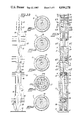
- FIG. 3A is a longitudinal sectional view showing the internal construction of a single one of the electron beam optical channels employed in the system of FIG. 1;
- FIGS. 3B is a schematic functional diagram of an electron beam optical channel such as shown in FIG. 3A and illustrates schematically the manner of operation of the single electron beam channel;
- FIGS. 4A-4E are cross sectional views taken transverse to the optical axis of the single deflection stage electron beam optical channel shown in FIG. 3A taken through the respective sections indicated by the corresponding figure numbers, with the aperture shapes shown in enlarged scale relative to the housing 11 for visibility;
- FIG. 5 is a functional block diagram showing the construction of the overall control system used for controlling a multiple channel electron beam optical column lithography system station according to the invention
- FIG. 6 is a functional block diagram of a portion of an enlarged control system for controlling a number of stations, such as that shown in FIG. 5, and illustrates the interconnection of the individual station elements and their control by an individual station computer together with the relation of the individual station computers to a common system executive computer connected to all of the station computers in the overall multi-station electron beam lithography system; and
- FIG. 6A is a functional block diagram which is interconnected to the block diagram of FIG. 6 and completes the illustration of the enlarged multiple station control system while viewed in conjunction with FIG. 6.
- FIG. 1 is a geometric plan view of the layout of a specific multi-channel electron beam optical column lithography system according to the invention wherein there are 12 separate, miniaturized, single electron beam optical columns shown at 11.
- the columns 11 are mounted within a common evacuated housing structure (not shown) that supports all of the electron beam optical columns 11 in an array with each column over a selected unique area of a common target surface shown at 12 in FIG. 1.
- the target surface 12 shown in FIG. 1 comprises a circular semiconductor target wafer of about 150 millimeters in diameter which is supported on a movable stage (to be described more fully hereinafter) capable of moving the target wafer within a planar x-y area lying within the plane of the drawing.
- each electron beam optical column 11 forms a separate channel that is fixed in space relative to the movable target surface 12 and possesses a restricted field of view shown at 13 over an area of about 1-2 millimeters square. This field of view 13 of each electron optical column 11 is due to the inclusion of a limited deflection capability within each electron column as will be described hereafter.
- Direct electron beam writing on a unique, square segmental area of the surface of the semiconductor target wafer 12 is achieved in a vector scan write-on-the-fly mode of operation.
- the overall field of view S of each electron beam optical column 11 is broken up into chip fields of typically several millimeters square as indicated at Cx and Cy in FIG. 2.
- the semiconductor chip circuit pattern to be written is segmented into stripes of height H equal to or less than the Y-deflection field of the electron beam columns.
- the stripes are broken into subfields which are of the order of 50 micrometers square.
- each subfield the circuit pattern to be written is divided into trapezoids and within each trapezoid the spot size and shape of the electron beam at any point within the sub-field is dynamically adjustable so as to accomplish writing of the pattern in minimum time.
- all 12 electron beam channels 11 are programmed to write the same pattern in parallel simultaneously so that the thru-put of the overall electron beam lithography system is greatly increased over prior art, serially operated electron beam writers.
- each electron beam optical column 11 To provide adjustability to the electron beam spot size and shape of each electron beam optical column 11 in order for it to carry out the above briefly described vector scan mode of operation, as well as to allow dynamic deflection of the shaped and sized electron beam within the limited 1-2 millimeter square field of view indicated at 13, a radically different and novel, all-electrostatic electron beam optical column design is provided.
- Each of the electron beam optical columns 11 is all-electrostatic and is capable of covering a 1-2 millimeter square field of view with a beam convergent half-angle of 6-7 milliradians while the writing electron beam produced by the column simultaneously is dynamically adjusted in spot shape and spot size.
- the design is such that even while deflected, the writing electron beam orthogonally lands on the target surface to which it is deflected within 0.2 milliradians and with an edge width, or total aberration equal to or less than 0.1 micrometers.
- magnetic electron optical columns are not suitable for multi-channel parallel electron beam lithography systems such as that illustrated in FIG. 1 because the relatively large diameter of the magnetic electron optical column precludes them being clustered over relatively small diameter semiconductor target wafers having a diameter of about 150 millimeters such as that depicted at 12 in FIG. 1.
- each electron beam optical column or channel is comprised by an outer elongated cylindrical housing member 11 preferably fabricated from a ceramic such as alumina, but may be formed from other insulating material.
- the electron optical sub-assemblies supported within housing 11 consists of three main sections which are further described in detail below and are comprised by an electron gun sub-assembly, an electron beam spot size and shaping sub-assembly, and an electron beam spot imaging and deflection sub-assembly.
- an electron gun sub-assembly an electron beam spot size and shaping sub-assembly
- an electron beam spot imaging and deflection sub-assembly A preferred method of fabrication of these sub-assemblies, the mounting and aligning of the sub-assemblies within the elongated housing member 11 and the manner of excitation with suitable electric power and control signals is described more fully in a co-pending U.S. application Ser. No.
- FIG. 3A and FIGS. 4A-4E are believed to illustrate the fabrication of the novel single electron beam optical column in sufficient detail to enable one of ordinary skill in the electron beam optics art to practice the invention.
- the electron gun employed in the electron beam optical column in the preferred embodiment consists of a cathode 15, a control grid 16 and an anode 17.
- the electron gun is designed to provide a bright (1-3 ⁇ 10 5 A/centimeter square/ster at 10 KV) stable and long lived (greater than 2000 operating hours) electron source.
- One suitable electron source for this purpose is described in co-pending U.S. application Ser. No. 749,787 filed June 28, 1985 concurrently with this application and entitled "Sapphire-Grided Flat Cathode Electron Gun"- J. Valun and K. J. Harte, inventors.
- For a more detailed description of the construction and operation of the electron gun reference is made to this co-pending U.S. application Ser. No. 749,787.
- Other known cathode guns of comparable charactristics also could be used.
- beam steering deflector 18 which consitutes a four-fold deflector that centers the electron beam supplied by the electron gun sections 15, 16 and 17 and causes the beam to enter the next section of the electron beam optical column along the undeflected center axis of the optical column indicated at 19.
- the beam steering deflector 18 compensates for any misalignment or stray magnetic fields present in the electron gun and eliminates the need for in situ mechanical adjustment of the electron beam optical column when mounting it in operating position as illustrated in FIGS. 1 and 5 of the drawings.
- the electron gun sub-assembly is completed by an apertured plate 21 having a central circular aperture 21A therein as shown in FIG. 4A of the drawings and which is secured in housing 11 at the output end of the electron gun assembly.
- the aperture 21A in effect serves as a limiting aperture which limits the cross sectional area of the electron beam as it leaves the electron gun assembly.
- This sub-assembly provides a means for turning the electron beam on and off at high speed through the provision of a beam blanking deflector and blanking plate followed by an electron beam spot size and shaping section.
- the beam blanking deflector includes a two-fold deflector comprised by a first deflector section 22 and a second deflector section 23 which upon application of a suitable blanking voltage pulse thereto causes the electron beam to be deflected out to and impinge upon a blanking apertured plate 25 having a central circular aperture 25A therein (FIG. 4C). Blanking in this manner is illustrated by the dotted line path 19B of the electron beam shown in FIG. 3B of the drawings.
- high speed turn-off of the electron beam can be achieved through the application of a blanking potential to the blanking deflector sections 22 and 23 and high speed turn-on of the beam is achieved by removal of the blanking potential whereby the electron beam will return to the path along its central, undeflected axis 19.
- Spot size and shaping of the electron beam is achieved by a first spot shaping apertured plate 26 mounted along the longitudinal axis of the electron beam optical column between the beam blanking deflector sections 22 and 23 and having a square aperture opening 26A centrally located about the undeflected axis 19 of the electron beam path as shown in FIG. 4B.
- a desired electron beam spot size and shape is formed by imaging the square shaped aperture 26A of first plate 26 onto a desired one of a plurality of different shaped aperture openings 27A in a second imaged apertured plate 27. As best seen in FIG.
- apertured plate 27 has a plurality of different shape and different size apertured openings having configurations such as delta shaped openings, the deltas having different orientations, a central square opening and a plurality of circular openings of different diameters.
- the electron beam spot of a desired size and shape is formed by imaging the first imaged aperture 26A onto a desired one of the second imaged apertures 27A by means of two spot shaping lenses 28 and 29 and two spot shaping deflectors 31 and 32.
- the second imaged aperture 27A is in turn imaged onto the target surface 12 by the spot imaging and deflection sub-assembly to be described hereafter.
- the first imaged aperture 26A comprises a single central square hole
- the second imaged aperture 27A may comprise either a square, a triangular hole of any desired orientation or a circular opening of a desired size required to fit a particular semiconductor device circuit pattern requirement.
- the spot size and shape is changed by deflecting the first imaged aperture 26A with the first spot shaping deflector 31 in a manner such that the image of the first imaged aperture 26A falls at a desired location on the second apertured plate 27, thereby reproducing truncated rectangles, or right isosceles triangles, or the like of any desired size and orientation up to a maximum size (typically 2.5 microns).
- the second spot shaping deflector 32 restores the sized and shaped electron beam leaving the second imaged apertured plate 27 back to the central optical axis 19 thereby making the image of the first imaged apertured plate 26 (which now is partially truncated both in size and shape by the second imaged aperture 27A) to remain fixed along the central undeflected axis of the electron beam 19 relative to the workpiece or target 12.
- This is achieved by placing the two spot shaping deflectors 31 and 32 in conjugate image planes of lens 29, and avoids the need to correct the electron beam spot position as its size and/or shape is varied.
- the first spot-shaping apertured plate 26 midway between the two equal length blanking deflector sections 22 and 23 motion of the electron beam spot position at the target 12 during blanking or unblanking is eliminated.
- the spot imaging and deflection sub-assembly serves to demagnify and focus the sized and shaped electron spot and to deflect it to a desired point within a 1-2 millimeter square field of view while keeping the deflected beam orthogonal to the plane of the target surface 12 at the deflected position thereby obviating the need for height adjustment to the beam.
- the beam spot imaging and deflection sub-assembly is comprised by a beam defining apertured plate 34 whose cross sectional configuration is shown in FIG. 4E of the drawings and which consititutes the limiting aperture of the electron beam optical system.
- the first active component following apertured plate 34 is a demagnification or condenser lens assembly 35 which comprises a three plate condenser lens element of conventional three-plate element lens design with the center plate at cathode potential.
- the purpose of this lens 35 is to achieve demagnification in two stages so as to allow shortening of the overall length of the electron beam column with its attendant advantages in size reduction for use in the lithography system.
- a three-stage octopole deflector comprised by three octopole deflector sections 36, 37 and 38.
- the octopole deflector sections 36, 37 and 38 each are constructed and operate in a manner described more fully in U.S. Pat. No. 4,142,132 issued Feb. 27, 1979 for a "Method and Means for Dynamic Correction of Electrostatic Deflectors"--Kenneth J. Harte, inventor and assigned to the Control Data Corporation.
- the three octople deflector sections 36, 37 and 38 serve, in conjunction with an objective lens section 39 sandwiched between the second octopole deflector section 37 and the third octopole deflector section 38 as described hereafter, to deflect the sized and shaped electron beam to any desired position within a 1-2 millimeter field of view centered about the center axis postion 19 of the undeflected electron beam, and sequentially to straighten out the electron beam thus deflected so that it lands on the target surface 12 at the deflected position at an angle which is substantially orthogonal with the surface of target surface or workpiece 12.
- the effect achieved is depicted in the diagramatic sketch shown in FIG. 3B at 19D in which the effect has been somewhat exaggerated in order to be viewed by the reader.
- the three octopole deflector sections 36, 37 and 38 are alternately cross wired, as shown in Table 1 below, such that only eight external electrical connections are required for each electron beam optical channel.
- deflection and correction voltages V1 through V8 are applied to the respective octopole deflector sections according to the method described in the above referenced U.S. Pat. No. 4,142,132 wherein the deflection voltages are applied antisymetrically around the octopole deflector, and the correction voltages are applied symetrically.
- the deflection voltages prefferably be subdivided into at least two levels: a relatively low-speed, high-accuracy (e.g. 5 microsecond, 16 to 18 bit) major field deflection, and a relatively high speed, low-accuracy (e.g. 50 nanosecond, 12 bit) minor field deflection.
- Major field deflection selects the desired subfield within the total deflection field of 1 to 2 millimeters, while minor field deflection selects the trapezoid being written and the individual electron beam spots within that trapezoid.
- the minor field deflection voltage is electronically superimposed ("floated") onto the major field deflection voltage.
- the octopole deflector sections can each be physically subdivided into two electrically isolated parts; on one part the major field deflection voltage is applied, while on the other the minor field voltage is applied.
- the lengths and spacing of the octopole deflector sections 36, 37 and 38 and the location of the objective lens assembly 39 must be chosen carefully and controlled accurately.
- the length of the second octopole deflector section 37 is twice the length of either the first section 36 or the third section 38, and the center of the objective lens assembly 39 is midway in the gap between the second deflector section 37 and the third deflector section 38.
- the objective lens 39 should be shifted slightly toward the target or workpiece 12, and the third octopole deflector section 38 made slightly shorter than the first octopole deflector section 36.
- the arrangement of the objective lens in this manner results in the unavoidable residual deflector aberration (coma) being substantially cancelled out by equal and opposite lens coma while the shortened final octopole deflector section 38 maintains orthogonal landing of the electron beam.
- the objective lens 39 comprises a three element lens and the configuration of the elements, particularly the center element which operates at high voltage, is chosen to minimize spherical aberration.
- the length of the center element and the gaps between the center element and the two outer elements is chosen to be approximately equal to the diameter of the opening of the center element, a fairly low spherical aberration of about 20 times focal length can be achieved, which is adequate to meet design requirements of the system, namely a focused and deflected beam having a total aberration of the order of 0.1 micrometers and a current density of 15 to 50 amperes per centimeter square.
- the outer lens element of objective lens 39 must perform and that is to provide dynamic focus correction.
- the field of view of the deflector system comprised by the three octopole deflector sections 36, 37 and 38 is not flat, but parabolic.
- a dynamic focus voltage must be generated which is proportional to the sum of the squares of the x and y deflection voltages applied to the octopole deflector sections 36, 37 and 38.
- the last component included in the electron beam optical column 11 is a backscatter detector 41 mounted at the electron beam output end of the column for detecting electrons scattered from fiducial marks previously imposed on the target semiconductor wafer 12 being written upon in order to properly calibrate the electron beam positioning during writing of desired semiconductor device circuit patterns as described hereafter.
- Electron beam writing is performed in a vector scan mode while the movable stage moves the selected target area for a particular electron beam channel beneath that channel. This action is best seen in FIGS. 1 and 2 of the drawings wherein, because of the limited (1-2 millimeter square) field of view of each channel, coverage of the entire target semiconductor wafer 12 surface is obtained by moving the stage upon which the target is supported continuously back and forth in tracks along the x-axis (for example) as best illustrated with respect to the channel 11A shown in FIG. 1.
- the electron beam of each channel is deflected at right angles to the target surface motion, namely in the y direction where the x axis is defined as right and left in the plane of the drawings and the y axis is defined as orthogonal to the x axis namely from top to bottom of the Figure in the plane of the paper.
- the movable support carriage for the target wafer 12 is stepped one track spacing (H) in the y direction until the entire square area S has been brought under the view of the particular electron beam channel 11A, for example, as well as the remaining eleven channels.
- the movable stage supporting the target wafer 12 must be monitored by a laser interferometer and control signals derived for feedback to control the stage movement x-y drive mechanism 48 (shown in FIG. 5) and the electron beam deflection plates in order to compensate for the continuous x motion and to correct for movable stage position errors.
- rotation of the movable stage (called yaw about the z axis perpendicular to the x-y plane as defined above) must be measured and feedback signals derived for use in deriving compensation signals also to be fed back to the deflection plates. This can be achieved either with an autocollimator or a laser interferometer. Since each electron beam channel is displaced by a different but known vector from the intersection of the x-y laser interferometer beam provided for this purpose, additional compensation must be provided in the deflection plate voltages supplied to the respective electron beam optical columns.
- a preferred method for solving this problem is constituted by a two-step process as shown in FIG. 2 of the drawings.
- the first step of the process provides a starting correction before any electron beam writing takes place and is obtained by measuring the location of fiducial marks at three or four widely spaced points within the target area to be covered by the respective channel. These fiducial marks are shown as small solid squares indicated at 41 in FIG. 2.
- the second step of the process is to measure the location of the fiducial marks located on the wafer along the chip track scribe lines which are shown as small open squares identified as 42 in FIG. 2. Using these measurements, the channel controllers then correct each channel "on the fly" as the wafer is written.
- the measurements obtained in the first step of the above briefly described two-step process are used to establish a set of coefficients (8 in all) which amongst other things correct for offset, rotation, gain and quadrilateral distortion in both the x and y directions.
- These correction signals then are supplied to the octopole deflector sections of the respective electron beam columns in order to correct the position of the electron beam relative to the assigned target area at the initiation of writing.
- corrections for process-induced wafer distortions between electron-beam exposure and for rapid thermal expansion effects is obtained by using the measurements derived during the second step of the process.
- An alternative registration method is to first measure the location of fiducial marks in the scribe lines (preferably at the corners) of the first row of chips (bottom row of 5 chips in FIG. 2). These measurements are then used to establish a set of correction in coefficients for each chip in the row. Then that row of chips is written with the beam corrected accordingly. Next, fiducial marks in the second row are measured (preferably using previous measurements of fiducial marks at the top of the first row where possible), and the process repeated to write the second row, and so forth through the entire field.
- FIG. 5 is a functional block diagram of a suitable control system for the multiple channel electron beam lithography system.
- the system comprises a single station of 12 channels supported within an outer evacuated housing 45 that also includes a movable stage 46 on which the semiconductor target wafer 12 is physically supported beneath the array of single electron beam optical channels 11, 11', 11", etc., comprising the station in the manner shown in FIG. 1 of the drawings.
- the movable target supporting stage 46 is coupled through a flexible bellows 47 or other similar means for maintaining the integrity of the vacuum within housing 45 via a drive shaft to a x-y stage translation mechanism 48 of conventional, commercially available construction.
- X-y stage translation mechanism 48 is in turn controlled in its x-y movement by a stage control 49 that in turn is controlled by a master station computer shown at 51.
- Master station computer 51 also directly controls a common high voltage and cathode power supply circuit 52 for all of the electron beam columns 11, 11', 11" etc., as well as common spot selection control circuit 53, a common objective lens control circuit 54 and a common pattern dependent deflection control circuit 55, all of which commonly control the respective similar-named parts of the multiple electron beam optical columns.
- the master station computer 51 via conductor cable 56 directly controls each of the respective channel controllers shown at 57-1, 57-2 and 57-3.
- Such functions include the individual channel controler 57-1, 57-2, 57-3, etc. which in turn respectively directly control the beam blanker control circuitry 58-1, 58-2, 58-3, etc.; the beam steering control circuitry 59-1, 59-2, 59-3, etc.; the individual electron gun grid control circuitry 61-1, 61-2, 61-3, etc.; the focus control and correction circuitry 62-1, 62-2, 62-3, etc.; the deflection correction circuitry 63-1, 63-2, 63-3, etc.; and the fiducial signal processing circuitry 64-1, 64-2, 64-3, etc. for each of the individual electron beam optical columns 11, 11', 11", etc.
- a pattern-data stripe buffer memory (not shown) is provided in the individual electron beam channel controllers 57-1, 57-2, 57-3, etc.
- This pattern-data stripe buffer memory is designed to store a particular part of the circuit pattern for each chip to be processed wherein each chip area is provided with a congruent stripe to be exposed as the stage is moved from one end of an x-axis track of movement to the other before being shifted one track space at the end of each track.
- FIG. 6 of the drawings is a functionl block diagram of an enlarged multi-channel electron beam lithography system according to the invention wherein there are a number of stations similar to that illustrated in FIG. 5 up to N station with each station having a number M of electron beam optical channels constructed according to the invention.
- an executive computer 65 is provided along with a complete pattern memory storing all of the semiconductor device circuit patterns to be written and which in turn communicates with and controls the operation of all of the N station computers 51 in the system.
- a common stage control 49, common high voltage and cathode power supply circuitry 52 is provided under the control of both the executive computer 65 and the station computers 51 for all of the electron beam optical columns in each station and for all of the stations.
- the system of FIG. 6 is similar to the system shown in FIG. 5 but illustrates how the multi-channel electron beam lithography system of FIG. 5 can be expanded into large microcircuit processing facilities.
- the multiple channel electron beam lithography system and method described and claimed in this application has its principle commercial use in the fabrication of microminiaturized semiconductor circuit patterns by direct electron beam writing on discrete assigned surface areas of enlarged semiconductor wafer targets used in the fabrication of electronic microcircuits.
Abstract
Description
              TABLE 1
______________________________________
Voltages applied to each of eight blades on
each of three deflector sections as a
result of alternate cross-wiring.
        Deflector Section
Blade     1st           2nd    3rd
No.       (16)          (17)   (21)
______________________________________
1         V.sub.5       V.sub.1
                               V.sub.5
2         V.sub.6       V.sub.2
                               V.sub.6
3         V.sub.7       V.sub.3
                               V.sub.7
4         V.sub.8       V.sub.4
                               V.sub.8
5         V.sub.1       V.sub.5
                               V.sub.1
6         V.sub.2       V.sub.6
                               V.sub.2
7         V.sub.3       V.sub.7
                               V.sub.3
8         V.sub.4       V.sub.8
                               V.sub.4
 ##STR1##
Blade Numbering Convention
(Looking from gun toward workpiece)
______________________________________
Claims (39)
Priority Applications (2)
| Application Number | Priority Date | Filing Date | Title |
|---|---|---|---|
| US06/749,796 US4694178A (en) | 1985-06-28 | 1985-06-28 | Multiple channel electron beam optical column lithography system and method of operation |
| JP61148372A JPS624363A (en) | 1985-06-28 | 1986-06-26 | Lithography apparatus for multi-channel charged particle beam optical columnar body and operation thereof |
Applications Claiming Priority (1)
| Application Number | Priority Date | Filing Date | Title |
|---|---|---|---|
| US06/749,796 US4694178A (en) | 1985-06-28 | 1985-06-28 | Multiple channel electron beam optical column lithography system and method of operation |
Publications (1)
| Publication Number | Publication Date |
|---|---|
| US4694178A true US4694178A (en) | 1987-09-15 |
Family
ID=25015237
Family Applications (1)
| Application Number | Title | Priority Date | Filing Date |
|---|---|---|---|
| US06/749,796 Expired - Lifetime US4694178A (en) | 1985-06-28 | 1985-06-28 | Multiple channel electron beam optical column lithography system and method of operation |
Country Status (2)
| Country | Link |
|---|---|
| US (1) | US4694178A (en) |
| JP (1) | JPS624363A (en) |
Cited By (48)
| Publication number | Priority date | Publication date | Assignee | Title |
|---|---|---|---|---|
| US4829444A (en) * | 1985-10-25 | 1989-05-09 | Hitachi, Ltd. | Charged particle beam lithography system |
| US4890239A (en) * | 1987-10-20 | 1989-12-26 | Shipley Company, Inc. | Lithographic process analysis and control system |
| US4974736A (en) * | 1987-04-28 | 1990-12-04 | Canon Kabushiki Kaisha | Multi-electron-beam pattern drawing apparatus |
| US5170293A (en) * | 1991-02-18 | 1992-12-08 | Sharp Kabushiki Kaisha | Exposure mechanism |
| US5399860A (en) * | 1992-09-28 | 1995-03-21 | Kabushiki Kaisha Toshiba | Electron optic column and scanning electron microscope |
| EP0736893A2 (en) * | 1995-04-06 | 1996-10-09 | Fujitsu Limited | Charged particle beam exposure method and apparatus |
| US5920073A (en) * | 1997-04-22 | 1999-07-06 | Schlumberger Technologies, Inc. | Optical system |
| WO1999047978A1 (en) * | 1998-03-20 | 1999-09-23 | Etec Systems Incorporated | Method and apparatus for direct writing of semiconductor die using microcolumn array |
| KR19990088179A (en) * | 1998-05-12 | 1999-12-27 | 히로시 오우라 | Electron-beam lithography system |
| US6046459A (en) * | 1997-04-11 | 2000-04-04 | Fujitsu Limited | Method and system for charged particle beam exposure |
| FR2791777A1 (en) * | 1999-01-08 | 2000-10-06 | Schlumberger Technologies Inc | DETECTION OF DEFECTS IN STRUCTURED SUBSTRATES |
| US6288772B1 (en) * | 1999-02-12 | 2001-09-11 | Nikon Corporation | Scanning exposure method and scanning type exposure apparatus |
| US20020020823A1 (en) * | 2000-05-15 | 2002-02-21 | Hsing-Yao Chen | Deflection lens device for electron beam lithography |
| US20020127050A1 (en) * | 1999-11-05 | 2002-09-12 | Andeen Gerry B. | Platform positioning system |
| US20030107008A1 (en) * | 2001-10-26 | 2003-06-12 | Jeol Ltd. | Lithographic method using variable-area electron-beam lithography machine |
| US6593584B2 (en) * | 1999-12-23 | 2003-07-15 | Fei Company | Multi-beam lithography apparatus with mutually different beam limiting apertures |
| US20030168606A1 (en) * | 2000-04-27 | 2003-09-11 | Pavel Adamec | Multi beam charged particle device |
| US20040065826A1 (en) * | 2000-02-25 | 2004-04-08 | Steve Berger | System for imaging a cross-section of a substrate |
| US20040069960A1 (en) * | 2002-10-10 | 2004-04-15 | Applied Materials, Inc. | Electron beam pattern generator with photocathode comprising low work function cesium halide |
| US6734428B2 (en) | 2000-02-19 | 2004-05-11 | Multibeam Systems, Inc. | Multi-beam multi-column electron beam inspection system |
| US20040119021A1 (en) * | 1999-11-23 | 2004-06-24 | Ion Diagnostics | Electron optics for multi-beam electron beam lithography tool |
| US20040140432A1 (en) * | 2002-10-10 | 2004-07-22 | Applied Materials, Inc. | Generating electrons with an activated photocathode |
| US20040140438A1 (en) * | 2001-01-19 | 2004-07-22 | Gerlach Robert L. | Angular aperture shaped beam system and method |
| US6797953B2 (en) | 2001-02-23 | 2004-09-28 | Fei Company | Electron beam system using multiple electron beams |
| US6797969B2 (en) | 2000-02-09 | 2004-09-28 | Fei Company | Multi-column FIB for nanofabrication applications |
| US20040232357A1 (en) * | 2001-01-31 | 2004-11-25 | Andres Fernadez | Electron beam lithography system having improved electron gun |
| US6835937B1 (en) * | 1999-12-13 | 2004-12-28 | Canon Kabushiki Kaisha | Correcting method for correcting exposure data used for a charged particle beam exposure system |
| US20050001165A1 (en) * | 2001-04-18 | 2005-01-06 | Parker N. William | Detector optics for charged particle beam inspection system |
| US20050001178A1 (en) * | 2000-02-19 | 2005-01-06 | Parker N. William | Multi-column charged particle optics assembly |
| US6844550B1 (en) | 2000-02-19 | 2005-01-18 | Multibeam Systems, Inc. | Multi-beam multi-column electron beam inspection system |
| GB2408143A (en) * | 2003-10-20 | 2005-05-18 | Ims Nanofabrication Gmbh | Charged-particle multi-beam exposure apparatus |
| US6949756B2 (en) | 2000-01-21 | 2005-09-27 | Fei Company | Shaped and low density focused ion beams |
| US6960767B1 (en) * | 1998-05-22 | 2005-11-01 | Micron Technology, Inc. | Apparatus for measuring features of a semiconductor device |
| US20050253093A1 (en) * | 2004-05-12 | 2005-11-17 | Gorski Richard M | Parallel multi-electron beam lithography for IC fabrication with precise X-Y translation |
| US20060055321A1 (en) * | 2002-10-10 | 2006-03-16 | Applied Materials, Inc. | Hetero-junction electron emitter with group III nitride and activated alkali halide |
| US7135675B1 (en) * | 2003-03-10 | 2006-11-14 | Kla-Tencor Technologies Corporation | Multi-pixel and multi-column electron emission inspector |
| US20080296515A1 (en) * | 2007-05-30 | 2008-12-04 | Nuflare Technology, Inc. | Charged particle beam writing apparatus and method |
| US20100205577A1 (en) * | 2009-02-11 | 2010-08-12 | Lee-Chung Lu | Design Methods for E-Beam Direct Write Lithography |
| US20100224781A1 (en) * | 2009-03-03 | 2010-09-09 | Jeol Ltd. | Electron Microscope |
| US20120235063A1 (en) * | 2011-03-18 | 2012-09-20 | Taiwan Semiconductor Manufacturing Company, Ltd. | Systems and Methods Providing Electron Beam Writing to a Medium |
| US20120273691A1 (en) * | 2011-04-28 | 2012-11-01 | Van Den Brom Alrik | Charged particle system for processing a target surface |
| US20130253688A1 (en) * | 2012-03-22 | 2013-09-26 | Nuflare Technology, Inc. | Multi charged particle beam writing apparatus and multi charged particle beam writing method |
| US20130293865A1 (en) * | 2011-09-06 | 2013-11-07 | Kla-Tencor Corporation | Linear Stage for Reflective Electron Beam Lithography |
| US20140008534A1 (en) * | 2012-07-06 | 2014-01-09 | Hitachi High-Technologies Corporation | Measuring/inspecting apparatus and measuring/inspecting method |
| US20150001419A1 (en) * | 2013-06-26 | 2015-01-01 | Canon Kabushiki Kaisha | Drawing apparatus, and method of manufacturing article |
| DE102015106704A1 (en) * | 2015-03-27 | 2016-09-29 | Taiwan Semiconductor Manufacturing Company, Ltd. | Electron beam lithography process with multiple columns |
| WO2021222085A1 (en) * | 2020-04-27 | 2021-11-04 | John Bennett | Modular parallel electron lithography |
| US11899375B2 (en) | 2020-11-20 | 2024-02-13 | Kla Corporation | Massive overlay metrology sampling with multiple measurement columns |
Citations (6)
| Publication number | Priority date | Publication date | Assignee | Title |
|---|---|---|---|---|
| US3491236A (en) * | 1967-09-28 | 1970-01-20 | Gen Electric | Electron beam fabrication of microelectronic circuit patterns |
| US4151422A (en) * | 1977-06-30 | 1979-04-24 | Rikagaku Kenkyusho | Electron beam exposure method |
| US4200794A (en) * | 1978-11-08 | 1980-04-29 | Control Data Corporation | Micro lens array and micro deflector assembly for fly's eye electron beam tubes using silicon components and techniques of fabrication and assembly |
| US4213053A (en) * | 1978-11-13 | 1980-07-15 | International Business Machines Corporation | Electron beam system with character projection capability |
| US4390789A (en) * | 1981-05-21 | 1983-06-28 | Control Data Corporation | Electron beam array lithography system employing multiple parallel array optics channels and method of operation |
| US4465934A (en) * | 1981-01-23 | 1984-08-14 | Veeco Instruments Inc. | Parallel charged particle beam exposure system |
-
1985
- 1985-06-28 US US06/749,796 patent/US4694178A/en not_active Expired - Lifetime
-
1986
- 1986-06-26 JP JP61148372A patent/JPS624363A/en active Pending
Patent Citations (6)
| Publication number | Priority date | Publication date | Assignee | Title |
|---|---|---|---|---|
| US3491236A (en) * | 1967-09-28 | 1970-01-20 | Gen Electric | Electron beam fabrication of microelectronic circuit patterns |
| US4151422A (en) * | 1977-06-30 | 1979-04-24 | Rikagaku Kenkyusho | Electron beam exposure method |
| US4200794A (en) * | 1978-11-08 | 1980-04-29 | Control Data Corporation | Micro lens array and micro deflector assembly for fly's eye electron beam tubes using silicon components and techniques of fabrication and assembly |
| US4213053A (en) * | 1978-11-13 | 1980-07-15 | International Business Machines Corporation | Electron beam system with character projection capability |
| US4465934A (en) * | 1981-01-23 | 1984-08-14 | Veeco Instruments Inc. | Parallel charged particle beam exposure system |
| US4390789A (en) * | 1981-05-21 | 1983-06-28 | Control Data Corporation | Electron beam array lithography system employing multiple parallel array optics channels and method of operation |
Cited By (79)
| Publication number | Priority date | Publication date | Assignee | Title |
|---|---|---|---|---|
| US4829444A (en) * | 1985-10-25 | 1989-05-09 | Hitachi, Ltd. | Charged particle beam lithography system |
| US4974736A (en) * | 1987-04-28 | 1990-12-04 | Canon Kabushiki Kaisha | Multi-electron-beam pattern drawing apparatus |
| US4890239A (en) * | 1987-10-20 | 1989-12-26 | Shipley Company, Inc. | Lithographic process analysis and control system |
| US5170293A (en) * | 1991-02-18 | 1992-12-08 | Sharp Kabushiki Kaisha | Exposure mechanism |
| US5399860A (en) * | 1992-09-28 | 1995-03-21 | Kabushiki Kaisha Toshiba | Electron optic column and scanning electron microscope |
| EP0736893A2 (en) * | 1995-04-06 | 1996-10-09 | Fujitsu Limited | Charged particle beam exposure method and apparatus |
| US5895924A (en) * | 1995-04-06 | 1999-04-20 | Fujitsu Limited | Charged particle beam exposure method and apparatus |
| EP0736893A3 (en) * | 1995-04-06 | 1999-07-21 | Fujitsu Limited | Charged particle beam exposure method and apparatus |
| US6046459A (en) * | 1997-04-11 | 2000-04-04 | Fujitsu Limited | Method and system for charged particle beam exposure |
| US5920073A (en) * | 1997-04-22 | 1999-07-06 | Schlumberger Technologies, Inc. | Optical system |
| WO1999047978A1 (en) * | 1998-03-20 | 1999-09-23 | Etec Systems Incorporated | Method and apparatus for direct writing of semiconductor die using microcolumn array |
| US6145438A (en) * | 1998-03-20 | 2000-11-14 | Berglund; C. Neil | Method and apparatus for direct writing of semiconductor die using microcolumn array |
| KR19990088179A (en) * | 1998-05-12 | 1999-12-27 | 히로시 오우라 | Electron-beam lithography system |
| US6960767B1 (en) * | 1998-05-22 | 2005-11-01 | Micron Technology, Inc. | Apparatus for measuring features of a semiconductor device |
| FR2791777A1 (en) * | 1999-01-08 | 2000-10-06 | Schlumberger Technologies Inc | DETECTION OF DEFECTS IN STRUCTURED SUBSTRATES |
| US6288772B1 (en) * | 1999-02-12 | 2001-09-11 | Nikon Corporation | Scanning exposure method and scanning type exposure apparatus |
| US20020127050A1 (en) * | 1999-11-05 | 2002-09-12 | Andeen Gerry B. | Platform positioning system |
| US6872958B2 (en) | 1999-11-05 | 2005-03-29 | Multibeam Systems, Inc. | Platform positioning system |
| US20040119021A1 (en) * | 1999-11-23 | 2004-06-24 | Ion Diagnostics | Electron optics for multi-beam electron beam lithography tool |
| US6835937B1 (en) * | 1999-12-13 | 2004-12-28 | Canon Kabushiki Kaisha | Correcting method for correcting exposure data used for a charged particle beam exposure system |
| US6593584B2 (en) * | 1999-12-23 | 2003-07-15 | Fei Company | Multi-beam lithography apparatus with mutually different beam limiting apertures |
| US6949756B2 (en) | 2000-01-21 | 2005-09-27 | Fei Company | Shaped and low density focused ion beams |
| US6797969B2 (en) | 2000-02-09 | 2004-09-28 | Fei Company | Multi-column FIB for nanofabrication applications |
| US6734428B2 (en) | 2000-02-19 | 2004-05-11 | Multibeam Systems, Inc. | Multi-beam multi-column electron beam inspection system |
| US20050001178A1 (en) * | 2000-02-19 | 2005-01-06 | Parker N. William | Multi-column charged particle optics assembly |
| US6943351B2 (en) | 2000-02-19 | 2005-09-13 | Multibeam Systems, Inc. | Multi-column charged particle optics assembly |
| US6844550B1 (en) | 2000-02-19 | 2005-01-18 | Multibeam Systems, Inc. | Multi-beam multi-column electron beam inspection system |
| US20040065826A1 (en) * | 2000-02-25 | 2004-04-08 | Steve Berger | System for imaging a cross-section of a substrate |
| US6838668B2 (en) | 2000-02-25 | 2005-01-04 | Fei Company | System for imaging a cross-section of a substrate |
| US6727500B1 (en) | 2000-02-25 | 2004-04-27 | Fei Company | System for imaging a cross-section of a substrate |
| US6943349B2 (en) * | 2000-04-27 | 2005-09-13 | ICT Integrated Circuit Testing Gesellschaft für Halbleiterprüftechnik mbH | Multi beam charged particle device |
| US20030168606A1 (en) * | 2000-04-27 | 2003-09-11 | Pavel Adamec | Multi beam charged particle device |
| US20020020823A1 (en) * | 2000-05-15 | 2002-02-21 | Hsing-Yao Chen | Deflection lens device for electron beam lithography |
| US6677592B2 (en) * | 2000-05-15 | 2004-01-13 | Hsing-Yao Chen | Deflection lens device for electron beam lithography |
| US20040140438A1 (en) * | 2001-01-19 | 2004-07-22 | Gerlach Robert L. | Angular aperture shaped beam system and method |
| US20040232357A1 (en) * | 2001-01-31 | 2004-11-25 | Andres Fernadez | Electron beam lithography system having improved electron gun |
| US7095037B2 (en) * | 2001-01-31 | 2006-08-22 | Andres Fernadez | Electron beam lithography system having improved electron gun |
| US6797953B2 (en) | 2001-02-23 | 2004-09-28 | Fei Company | Electron beam system using multiple electron beams |
| US7122795B2 (en) | 2001-04-18 | 2006-10-17 | Multibeam Systems, Inc. | Detector optics for charged particle beam inspection system |
| US20050001165A1 (en) * | 2001-04-18 | 2005-01-06 | Parker N. William | Detector optics for charged particle beam inspection system |
| US20030107008A1 (en) * | 2001-10-26 | 2003-06-12 | Jeol Ltd. | Lithographic method using variable-area electron-beam lithography machine |
| US6753540B2 (en) * | 2001-10-26 | 2004-06-22 | Jeol Ltd. | Lithographic method using variable-area electron-beam lithography machine |
| US7446474B2 (en) | 2002-10-10 | 2008-11-04 | Applied Materials, Inc. | Hetero-junction electron emitter with Group III nitride and activated alkali halide |
| US20040069960A1 (en) * | 2002-10-10 | 2004-04-15 | Applied Materials, Inc. | Electron beam pattern generator with photocathode comprising low work function cesium halide |
| US20040140432A1 (en) * | 2002-10-10 | 2004-07-22 | Applied Materials, Inc. | Generating electrons with an activated photocathode |
| US7161162B2 (en) | 2002-10-10 | 2007-01-09 | Applied Materials, Inc. | Electron beam pattern generator with photocathode comprising low work function cesium halide |
| US20060055321A1 (en) * | 2002-10-10 | 2006-03-16 | Applied Materials, Inc. | Hetero-junction electron emitter with group III nitride and activated alkali halide |
| US7015467B2 (en) | 2002-10-10 | 2006-03-21 | Applied Materials, Inc. | Generating electrons with an activated photocathode |
| US7135675B1 (en) * | 2003-03-10 | 2006-11-14 | Kla-Tencor Technologies Corporation | Multi-pixel and multi-column electron emission inspector |
| GB2408143A (en) * | 2003-10-20 | 2005-05-18 | Ims Nanofabrication Gmbh | Charged-particle multi-beam exposure apparatus |
| GB2408143B (en) * | 2003-10-20 | 2006-11-15 | Ims Nanofabrication Gmbh | Charged-particle multi-beam exposure apparatus |
| US7214951B2 (en) | 2003-10-20 | 2007-05-08 | Ims Nanofabrication Gmbh | Charged-particle multi-beam exposure apparatus |
| US20050104013A1 (en) * | 2003-10-20 | 2005-05-19 | Ims Nanofabrication Gmbh | Charged-particle multi-beam exposure apparatus |
| US20050253093A1 (en) * | 2004-05-12 | 2005-11-17 | Gorski Richard M | Parallel multi-electron beam lithography for IC fabrication with precise X-Y translation |
| US7075093B2 (en) | 2004-05-12 | 2006-07-11 | Gorski Richard M | Parallel multi-electron beam lithography for IC fabrication with precise X-Y translation |
| US20080296515A1 (en) * | 2007-05-30 | 2008-12-04 | Nuflare Technology, Inc. | Charged particle beam writing apparatus and method |
| US7705321B2 (en) * | 2007-05-30 | 2010-04-27 | Nuflare Technology, Inc. | Charged particle beam writing apparatus and method |
| US8214773B2 (en) | 2009-02-11 | 2012-07-03 | Taiwan Semiconductor Manufacturing Company, Ltd. | Methods for E-beam direct write lithography |
| US20100205577A1 (en) * | 2009-02-11 | 2010-08-12 | Lee-Chung Lu | Design Methods for E-Beam Direct Write Lithography |
| US20100224781A1 (en) * | 2009-03-03 | 2010-09-09 | Jeol Ltd. | Electron Microscope |
| US8664599B2 (en) * | 2009-03-03 | 2014-03-04 | Jeol Ltd. | Electron microscope |
| US20120235063A1 (en) * | 2011-03-18 | 2012-09-20 | Taiwan Semiconductor Manufacturing Company, Ltd. | Systems and Methods Providing Electron Beam Writing to a Medium |
| US8368037B2 (en) * | 2011-03-18 | 2013-02-05 | Taiwan Semiconductor Manufacturing Company, Ltd. | Systems and methods providing electron beam writing to a medium |
| US8610083B2 (en) | 2011-03-18 | 2013-12-17 | Taiwan Semiconductor Manufacturing Company, Ltd. | Systems and methods providing electron beam writing to a medium |
| US20120273691A1 (en) * | 2011-04-28 | 2012-11-01 | Van Den Brom Alrik | Charged particle system for processing a target surface |
| US9362084B2 (en) * | 2011-04-28 | 2016-06-07 | Mapper Lithography Ip B.V. | Electro-optical element for multiple beam alignment |
| US9690213B2 (en) * | 2011-09-06 | 2017-06-27 | Kla-Tencor Corporation | Linear Stage for reflective electron beam lithography |
| US20130293865A1 (en) * | 2011-09-06 | 2013-11-07 | Kla-Tencor Corporation | Linear Stage for Reflective Electron Beam Lithography |
| JP2013197468A (en) * | 2012-03-22 | 2013-09-30 | Nuflare Technology Inc | Multi charged particle beam lithography apparatus and multi charged particle beam lithography method |
| US9159555B2 (en) * | 2012-03-22 | 2015-10-13 | Nuflare Technology, Inc. | Multi charged particle beam writing apparatus and multi charged particle beam writing method |
| US20130253688A1 (en) * | 2012-03-22 | 2013-09-26 | Nuflare Technology, Inc. | Multi charged particle beam writing apparatus and multi charged particle beam writing method |
| US8890096B2 (en) * | 2012-07-06 | 2014-11-18 | Hitachi High-Technologies Corporation | Measuring/inspecting apparatus and measuring/inspecting method enabling blanking control of electron beam |
| US20140008534A1 (en) * | 2012-07-06 | 2014-01-09 | Hitachi High-Technologies Corporation | Measuring/inspecting apparatus and measuring/inspecting method |
| US20150001419A1 (en) * | 2013-06-26 | 2015-01-01 | Canon Kabushiki Kaisha | Drawing apparatus, and method of manufacturing article |
| US10361067B2 (en) * | 2013-06-26 | 2019-07-23 | Canon Kabushiki Kaisha | Drawing apparatus, and method of manufacturing article by controlling a plurality of charged particle optical systems based on respective sets of sub-drawing regions |
| DE102015106704A1 (en) * | 2015-03-27 | 2016-09-29 | Taiwan Semiconductor Manufacturing Company, Ltd. | Electron beam lithography process with multiple columns |
| DE102015106704B4 (en) | 2015-03-27 | 2019-02-14 | Taiwan Semiconductor Manufacturing Company, Ltd. | Electron beam lithography process with multiple columns |
| WO2021222085A1 (en) * | 2020-04-27 | 2021-11-04 | John Bennett | Modular parallel electron lithography |
| US11899375B2 (en) | 2020-11-20 | 2024-02-13 | Kla Corporation | Massive overlay metrology sampling with multiple measurement columns |
Also Published As
| Publication number | Publication date |
|---|---|
| JPS624363A (en) | 1987-01-10 |
Similar Documents
| Publication | Publication Date | Title |
|---|---|---|
| US4694178A (en) | Multiple channel electron beam optical column lithography system and method of operation | |
| US4390789A (en) | Electron beam array lithography system employing multiple parallel array optics channels and method of operation | |
| US6903353B2 (en) | Charged particle beam exposure apparatus, device manufacturing method, and charged particle beam applied apparatus | |
| US6323499B1 (en) | Electron beam exposure apparatus and method, and device manufacturing method | |
| US5981962A (en) | Distributed direct write lithography system using multiple variable shaped electron beams | |
| US5376802A (en) | Stencil mask and charge particle beam exposure method and apparatus using the stencil mask | |
| US20110079730A1 (en) | Imaging system | |
| US6145438A (en) | Method and apparatus for direct writing of semiconductor die using microcolumn array | |
| WO2006053360A1 (en) | Registering device and method for a pattern lock system in a particle-beam exposure apparatus | |
| KR102215251B1 (en) | Multi-charged particle beam writing method and multi-charged particle beam writing apparatus | |
| KR100339140B1 (en) | Electron beam exposure apparatus | |
| US10607812B2 (en) | Multiple charged particle beam writing apparatus, and multiple charged particle beam writing method | |
| US5012105A (en) | Multiple-imaging charged particle-beam exposure system | |
| KR102410976B1 (en) | Multi charged particle beam drawing device and multi charged particle beam drawing method | |
| US5962859A (en) | Multiple variable shaped electron beam system with lithographic structure | |
| US8222619B2 (en) | Multi-column electron beam exposure apparatus and multi-column electron beam exposure method | |
| US6091202A (en) | Electron beam exposure apparatus with non-orthogonal electron emitting element matrix | |
| KR20210105308A (en) | Multi-beam writing method and multi-beam writing apparatus | |
| JP2001015428A (en) | Electron beam exposure system | |
| JPH09330870A (en) | Electron beam exposing device and its exposing method | |
| US6376137B1 (en) | Charged-particle-beam microlithography apparatus and methods including correction of stage-positioning errors using a deflector | |
| JPH06291025A (en) | Electron-beam aligner | |
| US9040942B1 (en) | Electron beam lithography with linear column array and rotary stage | |
| KR20240002197A (en) | Multi-charged particle beam writing method and multi-charged particle beam writing apparatus | |
| JPS6142130A (en) | Electron beam exposure apparatus |
Legal Events
| Date | Code | Title | Description |
|---|---|---|---|
| AS | Assignment |
Owner name: CONTROL DATA CORPORATION 8100-34TH AVENUE SOUTH MI Free format text: ASSIGNMENT OF ASSIGNORS INTEREST.;ASSIGNOR:HARTE, KENNETH J.;REEL/FRAME:004424/0870 Effective date: 19850626 |
|
| STCF | Information on status: patent grant |
Free format text: PATENTED CASE |
|
| FEPP | Fee payment procedure |
Free format text: PAYOR NUMBER ASSIGNED (ORIGINAL EVENT CODE: ASPN); ENTITY STATUS OF PATENT OWNER: LARGE ENTITY |
|
| FPAY | Fee payment |
Year of fee payment: 4 |
|
| FEPP | Fee payment procedure |
Free format text: PAYER NUMBER DE-ASSIGNED (ORIGINAL EVENT CODE: RMPN); ENTITY STATUS OF PATENT OWNER: LARGE ENTITY |
|
| AS | Assignment |
Owner name: ST. CLAIR INTELLECTUAL PROPERTY CONSULTANTS, INC. Free format text: ASSIGNMENT OF ASSIGNORS INTEREST.;ASSIGNOR:CERIDIAN CORPORATION;REEL/FRAME:006276/0183 Effective date: 19920727 |
|
| FEPP | Fee payment procedure |
Free format text: PAYOR NUMBER ASSIGNED (ORIGINAL EVENT CODE: ASPN); ENTITY STATUS OF PATENT OWNER: LARGE ENTITY |
|
| FPAY | Fee payment |
Year of fee payment: 8 |
|
| FEPP | Fee payment procedure |
Free format text: PAYER NUMBER DE-ASSIGNED (ORIGINAL EVENT CODE: RMPN); ENTITY STATUS OF PATENT OWNER: LARGE ENTITY |
|
| FPAY | Fee payment |
Year of fee payment: 12 |