US4686798A - Optical blank carrier for lathing lenses and process therefor - Google Patents
Optical blank carrier for lathing lenses and process therefor Download PDFInfo
- Publication number
- US4686798A US4686798A US06/747,484 US74748485A US4686798A US 4686798 A US4686798 A US 4686798A US 74748485 A US74748485 A US 74748485A US 4686798 A US4686798 A US 4686798A
- Authority
- US
- United States
- Prior art keywords
- carrier
- optical blank
- blank
- machining
- double
- Prior art date
- Legal status (The legal status is an assumption and is not a legal conclusion. Google has not performed a legal analysis and makes no representation as to the accuracy of the status listed.)
- Expired - Fee Related
Links
Images


Classifications
-
- B—PERFORMING OPERATIONS; TRANSPORTING
- B24—GRINDING; POLISHING
- B24B—MACHINES, DEVICES, OR PROCESSES FOR GRINDING OR POLISHING; DRESSING OR CONDITIONING OF ABRADING SURFACES; FEEDING OF GRINDING, POLISHING, OR LAPPING AGENTS
- B24B13/00—Machines or devices designed for grinding or polishing optical surfaces on lenses or surfaces of similar shape on other work; Accessories therefor
- B24B13/005—Blocking means, chucks or the like; Alignment devices
-
- Y—GENERAL TAGGING OF NEW TECHNOLOGICAL DEVELOPMENTS; GENERAL TAGGING OF CROSS-SECTIONAL TECHNOLOGIES SPANNING OVER SEVERAL SECTIONS OF THE IPC; TECHNICAL SUBJECTS COVERED BY FORMER USPC CROSS-REFERENCE ART COLLECTIONS [XRACs] AND DIGESTS
- Y10—TECHNICAL SUBJECTS COVERED BY FORMER USPC
- Y10T—TECHNICAL SUBJECTS COVERED BY FORMER US CLASSIFICATION
- Y10T409/00—Gear cutting, milling, or planing
- Y10T409/30—Milling
- Y10T409/306664—Milling including means to infeed rotary cutter toward work
- Y10T409/306776—Axially
- Y10T409/307—Axially with work holder
-
- Y—GENERAL TAGGING OF NEW TECHNOLOGICAL DEVELOPMENTS; GENERAL TAGGING OF CROSS-SECTIONAL TECHNOLOGIES SPANNING OVER SEVERAL SECTIONS OF THE IPC; TECHNICAL SUBJECTS COVERED BY FORMER USPC CROSS-REFERENCE ART COLLECTIONS [XRACs] AND DIGESTS
- Y10—TECHNICAL SUBJECTS COVERED BY FORMER USPC
- Y10T—TECHNICAL SUBJECTS COVERED BY FORMER US CLASSIFICATION
- Y10T409/00—Gear cutting, milling, or planing
- Y10T409/40—Broaching
- Y10T409/405775—Broaching with means to hold work during cutting
Definitions
- the present invention relates to a process and apparatus for the manufacture of hard and soft contact lenses, more particularly to a carrier for a polymer button. Specifically, the present invention relates to polymer button carrier which is itself machinable, for use during a lathing process in the manual or automated manufacture of a contact lens.
- a polymer button is mounted (e.g. using a blocking wax or the like) on a first metal (e.g. steel) pin.
- the pin is gripped in the chuck of a lathe, the pin/button assembly is rotated, and a cut is made in the exposed surface of the button. This cut becomes the posterior or base curve.
- Another cut is made into the side of the button, while the button is still rotating about the same axis as it rotated about during cutting of the base curve; this is a ledge cut and is called a base curve reference.
- the base curve is polished and the button is removed from the pin.
- the pin/button assembly is released from the chuck, the button is removed from the pin, and that surface of the button which was attached to the pin is cleaned (this will become the anterior surface of the lens).
- the center thickness of the button is measured (from the apex of the base curve to the nearest opposing uncut surface).
- the button is then re-mounted, this time by attaching the base curve to a second metal pin having a surface reciprocal to the base curve, taking care to allign the turning axis of the pin with the base curve reference.
- the second pin is gripped in the chuck of a lathe, the pin/button assembly is rotated, and a cut (or series of cuts) is made in the exposed surface of the polymer button; this forms the front curve(s) of the contact lens.
- the front surface is then polished.
- the button is cut by removing an annular segment from it, to form the final diameter of the lens.
- the second pin/button assembly is then released from the chuck.
- the lens is removed from the second pin and cleaned of the blocking wax (or other attachment media) by physical and/or chemical methods known in the art. The edge of the lens is polished.
- the cut button (called a xerogel replica) is then hydrated, extracted, and placed in an appropriate solution and container for storage and sale.
- the mounting, de-mounting and re-mounting process has been both time-consuming and inaccurate, and a particularly problematic part of prior contact lens manufacturing processes.
- One undesirable result of the inaccuracy inherent in mounting and remounting the button is the creation of undesired prism between the anterior and posterior surfaces of the finished lens.
- Another undesirable aspect of having to de-mount and re-mount the buttons is that this renders the lathing manufacturing process very difficult to automate.
- metal pins used in the above-described process are somewhat expensive and cannot, therefore, be treated as a disposable item. They must, therefore, be cleaned (another time-consuming and expensive process) and reused, in order to maintain reasonable manufacturing costs.
- Another undesirable attribute of using metal pins is that, on occasion, when a cutting tool (usually an expensive diamond tipped tool) is moved too far through the button, the tool digs into the pin, destroying both the pin and itself.
- a button carrier is provided with a threaded inner surface and a reciprocally threaded surface is cut into a button.
- the button is then threaded into the carrier for making a first cut on one surface. It is then removed from the carrier, inverted, and re-inserted (by screwing it into the carrier) for the cuts on the other surface.
- This did not eliminate the demounting and remounting steps identified above as a problem, nor did it assure the absence of prism, as the re-insertion of the lens does not guarantee alignment of the button on the same axis of rotation for cutting the second surface.
- Another object of the present invention is to provide a contact lens which has absolutely no appreciable prism between its anterior and posterior curves.
- a related object of the present invention is to provide a contact lens having a precisely controlled prismatic component between its anterior and posterior surfaces.
- Still another object of the present invention is to provide a contact lens in accordance with the foregoing objects which is easier, quicker and less expensive to manufacture.
- Yet another object of the present invention is to provide a contact lens having an edge, the thickness of which is uniform to within ⁇ 0.01 mm throughout.
- a still further object of the invention is to provide a carrier for a polymer button which is susceptible to being used in a fully automated process for the manufacture of contact lenses, without need for de-mounting and re-mounting the button between the cutting steps for the anterior and posterior surfaces.
- a further object of the invention is to provide a button carrier in accordance with the foregoing objects which is both inexpensive to manufacture and, therefore, disposable.
- Another object of the present invention is to provide a button carrier which will not damage the tool used to cut the polymer button in the event of accidental contact between that tool and the button carrier.
- a carrier for supporting an optical blank in the chuck of a lathe, for machining the optical blank into a lens.
- the carrier has a body formed of a machinable material.
- the body has an opening through which an optical blank can be inserted, and a retaining portion for securing such optical blank in place.
- the body is cylindrical and the retaining portion is an annular shoulder extending inwardly at an end of the body opposite the opening.
- the carrier preferably has: a substantially cylindrical first, retaining portion; a larger diameter, substantially cylindrical, second portion; and a conical third portion therebetween.
- the invention discloses a process for manufacturing a lens from an optical blank, including the steps of:
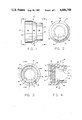
- FIG. 1 is a side plan view of a button carrier embodying the principles of the present invention, shown enlarged for ease of illustration;
- FIG. 2 is an end plan view of the button carrier of FIG. 1, taken along line 2--2 in FIG. 1;
- FIG. 3 is a plan view of the other end of the button carrier of FIG. 1, taken along line 3--3 in FIG. 1;
- FIG. 4 is a cross-sectional view of a button carrier embodying the principles of the present invention, taken along line 4--4 in FIG. 3;
- FIG. 5 is a cross-sectional view of a button carrier embodying the principles of the present invention, similar to the view shown in FIG. 4, illustrating a polymer button inserted into the button carrier;
- FIG. 6 is another view of the carrier/button assembly of FIG. 5, shown mounted in a chuck with a base curve cut into the button and a mounting surface cut into the button carrier;
- FIG. 7 is another view of the carrier/button assembly of FIG. 6, shown mounted in a chuck with a front curve cut into the button and extending into the button carrier;
- FIG. 8 is another view of the carrier/button assembly of FIG. 7, shown with an annular portion removed from the circumference of the lathed button to form the final diameter of a contact lens or replica;
- FIG. 9 is a cross-sectional view of another embodiment of a carrier/button assembly embodying the principles of the present invention, adapted for making two lenses from a single button.
- a button carrier 10 has a first end 11 and a second end 12 defining end walls 13 and 14 respectively, connected together by a wall 16 having an inner surface 18 and an outer surface 20.
- the button carrier 10 has a first portion 22 (adapted for receiving an optical blank, such as a polymer button for making a contact lens) and a second portion 24.
- the button carrier is generally cylindrical; the second portion 24 has a diameter greater than that of the first portion 22; the two portions 22 and 24 are connected together by a conical third portion 26; and the second portion 24 has a series of threads 36 on its inner surface 18.
- An inwardly extending shoulder 30 is disposed towards first end 11 of the button carrier, resulting in an opening 31.
- the shoulder 30 can be described as a thickening of the cylindrical wall 16 towards first end 11 to present a smaller diameter inner surface 32 and a connecting inner end wall 34.
- the first end wall 13 may be solid, replacing the flange or shoulder 30.
- other means e.g. an automated lathe
- the button carrier is fabricated of a somewhat rigid, dimensionally stable material that can be machined by lathing.
- the selected material will not interact adversely with the polymers from which contact lenses are typically made, nor with the waxes and like adhesives used in contact lens manufacturing processes.
- the button carrier may be fabricated of plastic (e.g. acrylic plastics), wood, or soft metal.
- the button carrier is preferably fabricated as a molded plastic part made, for example from polyethylene, polypropylene, polymethyl methacrylate or the like.
- FIGS. 5-8 A process for the manufacture of a lens by lathing a polymer button (or optical blank) held in the carrier of the present invention will be described with reference to FIGS. 5-8. It should be noted that the sequence of steps described in this paragraph may be varied, for example to adapt the process for automation.
- a polymer button 50 is inserted into a button carrier 10 through end 12 and retained in first portion 22 adjacent shoulder 30 by retaining means 52, such as an adhesive (e.g. blocking wax).
- the conical third portion 16 facilitates locating the polymer blank in place.
- the carrier/button assembly is gripped in a chuck 54 of a lathe, and rotated about an axis passing approximately through the center of the button and the hollow center of the button carrier (shown as line A--A in FIGS. 6 and 7).
- the first end 11 of the carrier/button assembly is inserted into a chuck 54 and gripped along outer surface 20 of cylindrical wall 16 of the first portion 22.
- an expanding gripping mechanism can be inserted into the smaller inner diameter surface 32 of flange 30 or other gripping methods may be used to hold the assembly for rotation.
- a cutting tool (not shown) is inserted through open end 12 of the button carrier and contacted with the polymer button 50 to form a posterior or base curve 56.
- a reference/mounting surface 58 (having line A--A as its central axis), for grasping the carrier in the chuck of a lathe, is cut into the outer surface 20 of cylindrical wall 16 in second portion 24 of the button carrier (removing the portion shown in dashed line in FIG. 6).
- This new diameter provides a reference/mounting surface 58 which is concentric with the base curve and perpendicular to the chordal plane of the base curve, and which is exactly concentric with the axis of rotation about which the base curve was cut.
- Reference/mounting surface 58 thereby allows the button to be rotated about axis A--A for subsequent cutting operations, i.e. to form the anterior surface of the lens with precise accuracy relative to the posterior surface.
- the carrier/button assembly is then released from the chuck 54.
- the center thickness of the button 50 is measured (from the apex of the base curve to the nearest opposing uncut surface).
- One method of making this measurement involves inserting a thickness gauge through the two open ends 11 (opening 31) and 12, to make contact with the button's surfaces.
- the carrier/button assembly is then filled (either partially or wholly) through the opening at end 12 with a supporting means 60 which may be the same or different from the adhesive means 52.
- the support fills the third portion 26 and at least part of the second portion 24 of the button carrier 10.
- the threads 36 function to help retain the support 60 in place within the carrier.
- the supporting means 60 holds the partially machined button securely for subsequent machining operations.
- the carrier/button assembly is then gripped in a chuck 62 of a turning lathe along the outer surface 20 of wall 16 of the second portion 24, i.e. reference/mounting surface 58.
- the carrier/button assembly is then rotated about axis A--A (the identical axis of rotation used to form the base curve 56).
- a cutting tool (not shown) is brought across the assembly towards its first end 11 to remove a portion (shown as dotted line 66 in FIG. 7) of both the carrier and the button, thereby forming a front surface 64 on the button 50.
- the front optical curve or curves of the contact lens to be produced may be formed by making one or more cuts on this front surface. The front surface is then polished.
- an annular segment (shown in dotted line as reference numeral 68) is removed from the outer periphery of the button 50, to cut the button to the final diameter of the contact lens or xerogel replica of this process, forming its outer edge 70.
- the button carrier is released from the chuck 62.
- the xerogel replica or lens 72 held thereon is removed from the supporting means 60 and cleaned of that adhesive by physical and/or chemical means well known in the art.
- the edge of the lens or xerogel replica 72 is then polished.
- the replica is then hydrated, extracted and placed in an appropriate solution and container for storage and sale, all of which are well known in the art.
- the axis of rotation can be changed for the cutting of the front surface, or the angle of the cutting tool can be changed.
- the degree of prism can be accurately maintained because of the ability to precisely set the rotational axis.
- the button carrier of the present invention satisfies all of the objects stated above.
- FIG. 9 Another embodiment of a button carrier of the present invention is adapted for the manufacture of two contact lenses from a single button; this embodiment is illustrated by reference numeral 80 in FIG. 9.
- the button carrier 80 can best be described as a pair of the button carriers 10 of the above-described embodiment joined together at end 11.
- a first portion 82 (somewhat elongated as compared to the first embodiment 10) is provided with a flange or shoulder 84, disposed at one end, against which to secure a button 86 (the button may be somewhat thicker than the button 50 employed with the first embodiment 10).
- the button can, alternatively, be held in place using only adhesive as the retaining means (i.e. with no shoulder 84).
- the carrier 80 has a pair of second portions 24 and 24a and a pair of third portions 26 and 26a.
- the button 86 is inserted into the carrier 80 and held in place by retaining means 52.
- the carrier is grasped for rotation. It may be grasped about first portion 82 to expose both sides of the button for cutting of base curves therein.
- carrier 80 may be grasped about second portion 24 to cut a base curve in a first exposed side of the button and to cut a mounting surface 58a into second portion 24a, and then grasped about second portion 24a to cut a base curve into the other side and a reference/mounting surface 58 into second portion 24 (illustrated by dashed lines 58 and 58a).
- the inside of the carrier is filled with adhesive material, as previously described, and the carrier is then cut in half, dividing it approximately across the center of the button 86 (e.g. along dashed line 90). The two halves are then treated as described above.
- the button carrier and method of the present invention can be used for holding optical blanks in cutting operations not limited to the manufacture of contact lenses, e.g. for microscope, telescope and camera lenses.
- the carrier can be provided with a shoulder at any selected point of its inner wall so that the optical blank can be held at any given point within the carrier, depending upon the kind of lens being made and the process chosen for making it.
- the disclosure and the description herein are purely illustrative and are not intended to be in any sense limiting.
Abstract
Description
Claims (11)
Priority Applications (1)
| Application Number | Priority Date | Filing Date | Title |
|---|---|---|---|
| US06/747,484 US4686798A (en) | 1985-06-21 | 1985-06-21 | Optical blank carrier for lathing lenses and process therefor |
Applications Claiming Priority (1)
| Application Number | Priority Date | Filing Date | Title |
|---|---|---|---|
| US06/747,484 US4686798A (en) | 1985-06-21 | 1985-06-21 | Optical blank carrier for lathing lenses and process therefor |
Publications (1)
| Publication Number | Publication Date |
|---|---|
| US4686798A true US4686798A (en) | 1987-08-18 |
Family
ID=25005257
Family Applications (1)
| Application Number | Title | Priority Date | Filing Date |
|---|---|---|---|
| US06/747,484 Expired - Fee Related US4686798A (en) | 1985-06-21 | 1985-06-21 | Optical blank carrier for lathing lenses and process therefor |
Country Status (1)
| Country | Link |
|---|---|
| US (1) | US4686798A (en) |
Cited By (15)
| Publication number | Priority date | Publication date | Assignee | Title |
|---|---|---|---|---|
| US4761315A (en) * | 1986-08-14 | 1988-08-02 | Gerber Scientific Products, Inc. | Blank for use in a lens pattern generator |
| US4856234A (en) * | 1988-02-26 | 1989-08-15 | Research Machine Center, Inc. | Optical lens manufacturing apparatus and method |
| GB2230983A (en) * | 1989-05-05 | 1990-11-07 | Gilco Optics Limited | Lens blank mountings |
| US5071101A (en) * | 1990-03-26 | 1991-12-10 | Wood Kenneth E | Mold for an intraocular/contact lens |
| US5110278A (en) * | 1990-11-30 | 1992-05-05 | Pilkington Visioncare, Inc. | Injection molding apparatus for producing a toric lens casting mold arbor |
| US5283984A (en) * | 1991-10-10 | 1994-02-08 | Lyric Optical Company, Inc. | Lens axis alignment device for use in a lens-surfacing machine |
| US5408792A (en) * | 1991-09-05 | 1995-04-25 | Gottschald; Lutz | Process, block or sucker for a machine for grinding or machining the edge of eyeglass lenses and a process for grinding eyeglass lenses |
| US5454748A (en) * | 1991-09-05 | 1995-10-03 | Wernicke & Co. Gmbh | Process, block for sucker or a machine for grinding or machining the edge of eyeglass lenses and a process for grinding eyeglass lenses |
| US5972251A (en) * | 1996-10-16 | 1999-10-26 | Bausch & Lomb Incorporated | Method for blocking a contact lens button |
| WO2004044633A1 (en) * | 2002-11-11 | 2004-05-27 | Cube Optics Ag | Support element for mounting optical elements and method for production of such a support element |
| US20040134234A1 (en) * | 2002-11-14 | 2004-07-15 | Oded Katzman | Lens production method and process |
| US20040166784A1 (en) * | 2002-11-14 | 2004-08-26 | Oded Katzman | Lens production method and process |
| US20050075060A1 (en) * | 2003-10-02 | 2005-04-07 | Konrad Bergandy | Apparatus for precision alignment during blocking process of lens manufacturing |
| US20060117919A1 (en) * | 2004-12-06 | 2006-06-08 | Hank Stute | Method and apparatus for manufacturing contact lenses |
| US20060120705A1 (en) * | 2004-12-06 | 2006-06-08 | Hank Stute | Method and apparatus for manufacturing contact lenses |
Citations (15)
| Publication number | Priority date | Publication date | Assignee | Title |
|---|---|---|---|---|
| US19015A (en) * | 1858-01-05 | Improvement | ||
| US1952373A (en) * | 1924-04-10 | 1934-03-27 | American Optical Corp | Lens blocking device |
| US2304984A (en) * | 1939-07-25 | 1942-12-15 | Eastman Kodak Co | Lens mount |
| US2585287A (en) * | 1949-01-13 | 1952-02-12 | Eastman Kodak Co | Apparatus for chucking blocks of lenses on generating machines |
| US3030859A (en) * | 1959-05-25 | 1962-04-24 | Jr Daniel O Elliott | Method of making contact lenses |
| US3032936A (en) * | 1958-08-08 | 1962-05-08 | Stolper & Voice Optical Compan | Contact lens polishing assembly |
| US3064531A (en) * | 1960-05-31 | 1962-11-20 | Giles E Bullock | Process for forming contact lenses |
| US3079737A (en) * | 1961-04-17 | 1963-03-05 | Plastic Contact Lens Company | Toric lens tool |
| US3153960A (en) * | 1960-08-08 | 1964-10-27 | Plastic Contact Lens Company | Contact lens cutting apparatus |
| US4113224A (en) * | 1975-04-08 | 1978-09-12 | Bausch & Lomb Incorporated | Apparatus for forming optical lenses |
| US4155962A (en) * | 1977-05-25 | 1979-05-22 | Neefe Optical Laboratory, Inc. | Method of removing molded lenses from the mold |
| US4179484A (en) * | 1977-05-25 | 1979-12-18 | Neefe Charles W | Method of making toric lenses |
| US4188353A (en) * | 1977-05-25 | 1980-02-12 | Neefe Charles W | Method of making aspheric lenses |
| US4197266A (en) * | 1974-05-06 | 1980-04-08 | Bausch & Lomb Incorporated | Method for forming optical lenses |
| US4468890A (en) * | 1979-08-02 | 1984-09-04 | Yoshiaki Nagaura | Apparatus for the manufacture of lens-like articles and the like |
-
1985
- 1985-06-21 US US06/747,484 patent/US4686798A/en not_active Expired - Fee Related
Patent Citations (15)
| Publication number | Priority date | Publication date | Assignee | Title |
|---|---|---|---|---|
| US19015A (en) * | 1858-01-05 | Improvement | ||
| US1952373A (en) * | 1924-04-10 | 1934-03-27 | American Optical Corp | Lens blocking device |
| US2304984A (en) * | 1939-07-25 | 1942-12-15 | Eastman Kodak Co | Lens mount |
| US2585287A (en) * | 1949-01-13 | 1952-02-12 | Eastman Kodak Co | Apparatus for chucking blocks of lenses on generating machines |
| US3032936A (en) * | 1958-08-08 | 1962-05-08 | Stolper & Voice Optical Compan | Contact lens polishing assembly |
| US3030859A (en) * | 1959-05-25 | 1962-04-24 | Jr Daniel O Elliott | Method of making contact lenses |
| US3064531A (en) * | 1960-05-31 | 1962-11-20 | Giles E Bullock | Process for forming contact lenses |
| US3153960A (en) * | 1960-08-08 | 1964-10-27 | Plastic Contact Lens Company | Contact lens cutting apparatus |
| US3079737A (en) * | 1961-04-17 | 1963-03-05 | Plastic Contact Lens Company | Toric lens tool |
| US4197266A (en) * | 1974-05-06 | 1980-04-08 | Bausch & Lomb Incorporated | Method for forming optical lenses |
| US4113224A (en) * | 1975-04-08 | 1978-09-12 | Bausch & Lomb Incorporated | Apparatus for forming optical lenses |
| US4155962A (en) * | 1977-05-25 | 1979-05-22 | Neefe Optical Laboratory, Inc. | Method of removing molded lenses from the mold |
| US4179484A (en) * | 1977-05-25 | 1979-12-18 | Neefe Charles W | Method of making toric lenses |
| US4188353A (en) * | 1977-05-25 | 1980-02-12 | Neefe Charles W | Method of making aspheric lenses |
| US4468890A (en) * | 1979-08-02 | 1984-09-04 | Yoshiaki Nagaura | Apparatus for the manufacture of lens-like articles and the like |
Cited By (18)
| Publication number | Priority date | Publication date | Assignee | Title |
|---|---|---|---|---|
| US4761315A (en) * | 1986-08-14 | 1988-08-02 | Gerber Scientific Products, Inc. | Blank for use in a lens pattern generator |
| US4856234A (en) * | 1988-02-26 | 1989-08-15 | Research Machine Center, Inc. | Optical lens manufacturing apparatus and method |
| GB2230983A (en) * | 1989-05-05 | 1990-11-07 | Gilco Optics Limited | Lens blank mountings |
| US5071101A (en) * | 1990-03-26 | 1991-12-10 | Wood Kenneth E | Mold for an intraocular/contact lens |
| US5110278A (en) * | 1990-11-30 | 1992-05-05 | Pilkington Visioncare, Inc. | Injection molding apparatus for producing a toric lens casting mold arbor |
| US5408792A (en) * | 1991-09-05 | 1995-04-25 | Gottschald; Lutz | Process, block or sucker for a machine for grinding or machining the edge of eyeglass lenses and a process for grinding eyeglass lenses |
| US5454748A (en) * | 1991-09-05 | 1995-10-03 | Wernicke & Co. Gmbh | Process, block for sucker or a machine for grinding or machining the edge of eyeglass lenses and a process for grinding eyeglass lenses |
| US5283984A (en) * | 1991-10-10 | 1994-02-08 | Lyric Optical Company, Inc. | Lens axis alignment device for use in a lens-surfacing machine |
| US5972251A (en) * | 1996-10-16 | 1999-10-26 | Bausch & Lomb Incorporated | Method for blocking a contact lens button |
| WO2004044633A1 (en) * | 2002-11-11 | 2004-05-27 | Cube Optics Ag | Support element for mounting optical elements and method for production of such a support element |
| US20040134234A1 (en) * | 2002-11-14 | 2004-07-15 | Oded Katzman | Lens production method and process |
| US20040166784A1 (en) * | 2002-11-14 | 2004-08-26 | Oded Katzman | Lens production method and process |
| US7121931B2 (en) * | 2002-11-14 | 2006-10-17 | Kti Technologies Ltd. | Lens production method and process |
| US20050075060A1 (en) * | 2003-10-02 | 2005-04-07 | Konrad Bergandy | Apparatus for precision alignment during blocking process of lens manufacturing |
| US20060194517A1 (en) * | 2003-10-02 | 2006-08-31 | Radtek Corporation | Method for precision alignment during a blocking process of lens manufacturing |
| US20060117919A1 (en) * | 2004-12-06 | 2006-06-08 | Hank Stute | Method and apparatus for manufacturing contact lenses |
| US20060120705A1 (en) * | 2004-12-06 | 2006-06-08 | Hank Stute | Method and apparatus for manufacturing contact lenses |
| US7187859B2 (en) | 2004-12-06 | 2007-03-06 | Paragon Vision Sciences, Inc. | Method and apparatus for manufacturing contact lenses |
Similar Documents
| Publication | Publication Date | Title |
|---|---|---|
| US4686798A (en) | Optical blank carrier for lathing lenses and process therefor | |
| US4856234A (en) | Optical lens manufacturing apparatus and method | |
| US6786802B2 (en) | Method for lathing a lens | |
| US3460928A (en) | Method of making lens molds | |
| EP1656248B1 (en) | Method for manufacturing ophthalmic lenses using circular blanks | |
| US5520568A (en) | Method of processing a lens and means for use in the method | |
| US4619082A (en) | Method of manufacturing a contact lens | |
| US4749530A (en) | Mold for and method of making contact and intraocular lenses | |
| JPS598504B2 (en) | Method for making a non-spherical composite optical surface and assembly for making a template for manufacturing the same surface | |
| US5972251A (en) | Method for blocking a contact lens button | |
| CA2952575A1 (en) | Integrated part fixturing for lathing processes | |
| US8186998B2 (en) | Blank-holding means and method of surveying same | |
| US6460436B1 (en) | Reversible micromachining locator | |
| US1952373A (en) | Lens blocking device | |
| US5330203A (en) | Method of generating a toric surface on a molding tool | |
| US4074469A (en) | Apparatus for manufacturing lenses | |
| US4924739A (en) | Method and apparatus for producing a contact lens | |
| EP0143253A1 (en) | Lens casting mold and process for using same in making an optical lens | |
| US2807982A (en) | Lens centering clamp and testing device | |
| US4078283A (en) | Method for making eyeglass frames | |
| US2225040A (en) | Apparatus for finishing contact lenses | |
| JPH0493142A (en) | Cutting work method of plastic lens | |
| US3924936A (en) | Method of and apparatus for aligning optical lenses | |
| USRE19015E (en) | Process of blocking ophthalmic | |
| JPH10282388A (en) | Lens holding structure capable of alignment, and dimension determining method of the lens holding structure |
Legal Events
| Date | Code | Title | Description |
|---|---|---|---|
| AS | Assignment |
Owner name: SYNTEX (U.S.A.) INC., 3401 HILLVIEW AVENUE, P.O. B Free format text: ASSIGNMENT OF ASSIGNORS INTEREST.;ASSIGNORS:PETTY, DEAN M.;SAGE, HOWARD M.;REEL/FRAME:004473/0655 Effective date: 19851011 |
|
| AS | Assignment |
Owner name: SOLA U.S.A. INC., 1100 EAST BELL ROAD, PHOENIX, AR Free format text: ASSIGNS NUNC PRO TUNC AS OF DECEMBER 19, 1985 THE ENTIRE INTEREST.;ASSIGNOR:SYNTEX (U.S.A.) INC. A CORP. OF DE.;REEL/FRAME:004561/0861 Effective date: 19860520 Owner name: SOLA U.S.A. INC., ARIZONA Free format text: ASSIGNS NUNC PRO TUNC AS OF DECEMBER 19, 1985 THE ENTIRE INTEREST;ASSIGNOR:SYNTEX (U.S.A.) INC. A CORP. OF DE.;REEL/FRAME:004561/0861 Effective date: 19860520 |
|
| FEPP | Fee payment procedure |
Free format text: PAYOR NUMBER ASSIGNED (ORIGINAL EVENT CODE: ASPN); ENTITY STATUS OF PATENT OWNER: LARGE ENTITY |
|
| FPAY | Fee payment |
Year of fee payment: 4 |
|
| REMI | Maintenance fee reminder mailed | ||
| LAPS | Lapse for failure to pay maintenance fees | ||
| FP | Lapsed due to failure to pay maintenance fee |
Effective date: 19950823 |
|
| STCH | Information on status: patent discontinuation |
Free format text: PATENT EXPIRED DUE TO NONPAYMENT OF MAINTENANCE FEES UNDER 37 CFR 1.362 |