US4668091A - Arrangement at a gas flow through cell for spectrophotometric analysis of chemical compounds - Google Patents
Arrangement at a gas flow through cell for spectrophotometric analysis of chemical compounds Download PDFInfo
- Publication number
- US4668091A US4668091A US06/690,500 US69050084A US4668091A US 4668091 A US4668091 A US 4668091A US 69050084 A US69050084 A US 69050084A US 4668091 A US4668091 A US 4668091A
- Authority
- US
- United States
- Prior art keywords
- channel
- compounds
- gas flow
- analysis
- gas
- Prior art date
- Legal status (The legal status is an assumption and is not a legal conclusion. Google has not performed a legal analysis and makes no representation as to the accuracy of the status listed.)
- Expired - Lifetime
Links
Images


Classifications
-
- G—PHYSICS
- G01—MEASURING; TESTING
- G01N—INVESTIGATING OR ANALYSING MATERIALS BY DETERMINING THEIR CHEMICAL OR PHYSICAL PROPERTIES
- G01N30/00—Investigating or analysing materials by separation into components using adsorption, absorption or similar phenomena or using ion-exchange, e.g. chromatography or field flow fractionation
- G01N30/02—Column chromatography
- G01N30/62—Detectors specially adapted therefor
- G01N30/74—Optical detectors
-
- G—PHYSICS
- G01—MEASURING; TESTING
- G01N—INVESTIGATING OR ANALYSING MATERIALS BY DETERMINING THEIR CHEMICAL OR PHYSICAL PROPERTIES
- G01N21/00—Investigating or analysing materials by the use of optical means, i.e. using sub-millimetre waves, infrared, visible or ultraviolet light
- G01N21/01—Arrangements or apparatus for facilitating the optical investigation
- G01N21/03—Cuvette constructions
- G01N21/05—Flow-through cuvettes
-
- G—PHYSICS
- G01—MEASURING; TESTING
- G01N—INVESTIGATING OR ANALYSING MATERIALS BY DETERMINING THEIR CHEMICAL OR PHYSICAL PROPERTIES
- G01N30/00—Investigating or analysing materials by separation into components using adsorption, absorption or similar phenomena or using ion-exchange, e.g. chromatography or field flow fractionation
- G01N30/02—Column chromatography
- G01N30/26—Conditioning of the fluid carrier; Flow patterns
- G01N30/28—Control of physical parameters of the fluid carrier
- G01N30/30—Control of physical parameters of the fluid carrier of temperature
- G01N2030/3053—Control of physical parameters of the fluid carrier of temperature using resistive heating
- G01N2030/3061—Control of physical parameters of the fluid carrier of temperature using resistive heating column or associated structural member used as heater
-
- G—PHYSICS
- G01—MEASURING; TESTING
- G01N—INVESTIGATING OR ANALYSING MATERIALS BY DETERMINING THEIR CHEMICAL OR PHYSICAL PROPERTIES
- G01N30/00—Investigating or analysing materials by separation into components using adsorption, absorption or similar phenomena or using ion-exchange, e.g. chromatography or field flow fractionation
- G01N30/02—Column chromatography
- G01N30/62—Detectors specially adapted therefor
- G01N30/74—Optical detectors
- G01N2030/746—Optical detectors detecting along the line of flow, e.g. axial
-
- G—PHYSICS
- G01—MEASURING; TESTING
- G01N—INVESTIGATING OR ANALYSING MATERIALS BY DETERMINING THEIR CHEMICAL OR PHYSICAL PROPERTIES
- G01N30/00—Investigating or analysing materials by separation into components using adsorption, absorption or similar phenomena or using ion-exchange, e.g. chromatography or field flow fractionation
- G01N30/02—Column chromatography
- G01N30/60—Construction of the column
- G01N30/6052—Construction of the column body
- G01N30/6082—Construction of the column body transparent to radiation
Definitions
- the present invention relates to an arrangement at a gas flow cell for spectrophotometric analysis of chemical compounds in the gas phase consisting of a longitudinal preferably cylindrical body with a longitudinal central channel which at both ends of the body is limited by two mutually parallel windows which are tighfitting against the channel and transparent for the radiation used at the analysis, which channel communicates at one end with connections for a carrier gas and for injecting compounds and at the other end has an outlet for the compounds and the carrier gas.
- Gas chromatographs has in general a size and complexity which imply that the instrument must be permanently installed in one place.
- the injector, column and detector are further on individually heated and the possibilities for identification of an unknown compound is strongly restricted with conventionel instruments equipped with unspecific detectors. Additional drawbacks are lengthy start up times, occasionally relatively long analysis times and high instrument costs.
- a primary object of the invention in question is to achieve a gas flow cell by initially described kind, by which the combinations GC/UV and GC/IR as well as enrichment of compounds can be carried out.
- the body is of an electrically leading polymeric material of a temperature self-regulating quality and has electric connections so that the body can be heated by connection to a voltage supply is obtained that through utilization of the body as a resistor element with temperature self-regulating characteristic depending on increasing resistance with increasing temperature the cell can be heated in a way that a good separation of the compounds is achieved.
- FIG. 1 in perspective shows a gas flow cell according to the present invention.
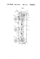
- FIG. 2 shows a longitudinal section through the gas flow cell in FIG. 1 and
- FIG. 3 and 4 show one of the ends of the gas flow cell seen in axial direction respectively across this direction.
- FIG. 1 represents a longish preferably cylindrical body with a longitudinal central channel 2.
- the body 1 preferably has such dimensions that if fits in the cuvette housing of a spectrophotometer and owing to technical and constructive reasons is made in four parts 1a, 1b, 1c and 1d which are kept together by screws 5 and, where so is necessary, are sealed with O-rings 6.
- Channel 2 is restricted at the both ends of the body 1 by mutually parallel windows 3,4 which are kept in place by the parts 1c and 1d and which are tightly connected to the channel 2.
- the windows 3, 4 are transparent for the radiation used at the analysis e.g. quartsglass at UV-detection and at IR-detection an IR-transparent material for example ZnSe.
- Channel 2 communicates partly with a connection channel 7 for carrier gas and partly with a connection channel 8 for injection the mixtures of compounds which are going to be analysed.
- connection channel 8 In the connection channel 8 there is a sealing injection membrane 9 through which injection can be carried out by a syringe.
- the opposite end of the channel 1 commuyeres with an outlet channel 10 for the compounds and the carrier gas.
- connection tubes 7a and 10a On the outside of the body there are connection tubes 7a and 10a which communicate with channels 7 and 10 respectively.
- a channel 11 serving for separation and/or enrichment connected between the connections 7,8 in which there are a replaceable column tube with a composition known to a man skilled in the art.
- Channel 2 and 11 communicate with each other at the both ends turned against the window 3 at the left hand side in FIG. 2.
- the channel 11 with the column tube 12 and its filling serves for separation of different compounds in a sample as will be explained in the following.
- the body is therefore made of an electrically conducting material e.g. a carbon filled polymeric with self-regulating temperature characteristic and equipped with connections 13, 14, 15 which can be connected to controlled voltage supply either by parallel connection through 13 and 14 resp 14 and 15 or in a series connection i.e. through 13 and 15 so that different kinds of heating of the body can be carried out.
- the channel 8 for the injection of the sample which is analysed goes through the connection 15.
- the column tube 12 of the instrument is extremely short.
- the support material in the column tube 12 is of considerably smaller particle sizes.
- These support materials are commercially available as column filling materials for liquid chromatography.
- the liquid phase can be applied in a manner similar to what is usual for normal GC-supports.
- the gas flow cell is placed in a spectrophotometer and the connection tube 7a for the carrier gas is connected to a gas supply and the electrical connections 13-15 to a voltage supply, not shown in the drawing.
- a defined voltage over the poles 13-15, a defined temperature is achieved in the body 1.
- the sample is injected through the injection membrane 9 and is forced out in the space just in front of the separation column 12. Injection of samples can be carried out either in the gas phase or in the liquid phase.
- the compound in the sample is separated in a known way in the liquid phase.
- the compound in the sample is separated in a known way in the column. When the separated compounds reach the channel 2, they are registered by the spectrophotometer and the absorbance (proportional against concentration) and signal from the detector of the spectrophotometer can be recorded on a recorder or treated by an integrator in an usual manner.
- Selective detection of compound groups are obtained by the selection of a suitable wavelength on the spectrophotometer.
- the analysis procedure is somewhat depending on the characteristics of the spectrophotometer.
- Advanced spectrophotometers having fast scanning possibilities can deliver a complete wavelength spectra while the compound is passing through the gas flow cell.
- simpler and slower spectrophotometers are used the gas flow is stopped when the compound is in position in the gas cell and the spectra is registered from the captured compound whereupon the gas flow again is allowed to flow.
Abstract
The present invention relates to a gas flow cell for spectrophotometric analysis of chemical compounds, consisting of a longish preferably cylindrical body (1) with a longitudinal central channel (2) which at the ends of the body (1) is limited by mutually parallel windows (3, 4) which are tightfitting against the channel (2) and transparent for the radiation used at the analysis. The channel (2) communicates at one end with connections (7, 8) for carrier gas and for injection of compounds and has at the other end an outlet (10) for the compounds and the carrier gas. Significant for the invention is that parallel with and at a distance from the mentioned channel (2) runs a second channel (11) serving for separation and connected between the connections (7, 8) and said end of the first mentioned channel (2). In this channel (11) there is a replaceable column tube (12) with filling of known composition.
Description
The present invention relates to an arrangement at a gas flow cell for spectrophotometric analysis of chemical compounds in the gas phase consisting of a longitudinal preferably cylindrical body with a longitudinal central channel which at both ends of the body is limited by two mutually parallel windows which are tighfitting against the channel and transparent for the radiation used at the analysis, which channel communicates at one end with connections for a carrier gas and for injecting compounds and at the other end has an outlet for the compounds and the carrier gas.
That part of analytical chemistry which is dealing with separation and detection of organic compounds in mixtures has ever since in the sixties been dominated by gas chromatography where the detection normally is obtained by an unspecific detector. More recently the technique has developed towards combinations of gas chromatography (GC) with qualitative analytical methods like mass spectroscopy (MS), IR-spectrophotometry (IR) or UV-spectrophotometry (UV). The advantage with these combinations is first of all that it gives possibilities for identification of compounds which are separated on the gas chromatograph. Further on it gives the possibility to achieve selective detection for example by selecting a wavelength on the UV- or IR-detector where only aromato compounds gives a response.
Gas chromatographs has in general a size and complexity which imply that the instrument must be permanently installed in one place. The injector, column and detector are further on individually heated and the possibilities for identification of an unknown compound is strongly restricted with conventionel instruments equipped with unspecific detectors. Additional drawbacks are lengthy start up times, occasionally relatively long analysis times and high instrument costs.
Commersially available instrument combinations exist for GC/IR and for GC/MS but not for GC/UV. The commercial combination of instruments are very costly and have complicated connections between the gas chromatograph and the spectrophotometer which makes it considerably difficult for changing to other analytical techiques like IR-analysis of compounds in the liquid phase. The high costs and the complexity has led to that most analytical laboratories with a particularly quantitative direction will have restricted possibilities for identification of compounds.
A primary object of the invention in question is to achieve a gas flow cell by initially described kind, by which the combinations GC/UV and GC/IR as well as enrichment of compounds can be carried out.
This is obtained according to the primary characteristic of the invention in that there is a second channel serving for separation connected between the connections and one of the ends of the first mentioned channel, in which channel there is replaceable column with column filling of a kind known per se.
In that the body, according to a special characteristic of the invention, is of an electrically leading polymeric material of a temperature self-regulating quality and has electric connections so that the body can be heated by connection to a voltage supply is obtained that through utilization of the body as a resistor element with temperature self-regulating characteristic depending on increasing resistance with increasing temperature the cell can be heated in a way that a good separation of the compounds is achieved.
In the following the invention will be further explained with reference to the attached drawing on which
FIG. 1 in perspective shows a gas flow cell according to the present invention.
FIG. 2 shows a longitudinal section through the gas flow cell in FIG. 1 and
FIG. 3 and 4 show one of the ends of the gas flow cell seen in axial direction respectively across this direction.
On the drawing numeral 1 represents a longish preferably cylindrical body with a longitudinal central channel 2. The body 1 preferably has such dimensions that if fits in the cuvette housing of a spectrophotometer and owing to technical and constructive reasons is made in four parts 1a, 1b, 1c and 1d which are kept together by screws 5 and, where so is necessary, are sealed with O-rings 6. Channel 2 is restricted at the both ends of the body 1 by mutually parallel windows 3,4 which are kept in place by the parts 1c and 1d and which are tightly connected to the channel 2. The windows 3, 4 are transparent for the radiation used at the analysis e.g. quartsglass at UV-detection and at IR-detection an IR-transparent material for example ZnSe. Channel 2 communicates partly with a connection channel 7 for carrier gas and partly with a connection channel 8 for injection the mixtures of compounds which are going to be analysed. In the connection channel 8 there is a sealing injection membrane 9 through which injection can be carried out by a syringe. The opposite end of the channel 1 commuincates with an outlet channel 10 for the compounds and the carrier gas. On the outside of the body there are connection tubes 7a and 10a which communicate with channels 7 and 10 respectively.
According to the invention there is a channel 11 serving for separation and/or enrichment connected between the connections 7,8 in which there are a replaceable column tube with a composition known to a man skilled in the art. Channel 2 and 11 communicate with each other at the both ends turned against the window 3 at the left hand side in FIG. 2. The channel 11 with the column tube 12 and its filling serves for separation of different compounds in a sample as will be explained in the following.
As is known there is as a rule a requirement for a defined temperature increase in order to separate different compounds in a sample. According to the present invention for this reason the body is therefore made of an electrically conducting material e.g. a carbon filled polymeric with self-regulating temperature characteristic and equipped with connections 13, 14, 15 which can be connected to controlled voltage supply either by parallel connection through 13 and 14 resp 14 and 15 or in a series connection i.e. through 13 and 15 so that different kinds of heating of the body can be carried out. The channel 8 for the injection of the sample which is analysed goes through the connection 15.
As can be seen the column tube 12 of the instrument is extremely short. In order to obtain comparable separation capacity as for conventionally packed GC-collumns the support material in the column tube 12 is of considerably smaller particle sizes. These support materials are commercially available as column filling materials for liquid chromatography. The liquid phase can be applied in a manner similar to what is usual for normal GC-supports.
The gas flow cell is placed in a spectrophotometer and the connection tube 7a for the carrier gas is connected to a gas supply and the electrical connections 13-15 to a voltage supply, not shown in the drawing. By applying a defined voltage over the poles 13-15, a defined temperature is achieved in the body 1. The sample is injected through the injection membrane 9 and is forced out in the space just in front of the separation column 12. Injection of samples can be carried out either in the gas phase or in the liquid phase. The compound in the sample is separated in a known way in the liquid phase. The compound in the sample is separated in a known way in the column. When the separated compounds reach the channel 2, they are registered by the spectrophotometer and the absorbance (proportional against concentration) and signal from the detector of the spectrophotometer can be recorded on a recorder or treated by an integrator in an usual manner.
Selective detection of compound groups are obtained by the selection of a suitable wavelength on the spectrophotometer.
At identification of compounds the analysis procedure is somewhat depending on the characteristics of the spectrophotometer. Advanced spectrophotometers having fast scanning possibilities can deliver a complete wavelength spectra while the compound is passing through the gas flow cell. When simpler and slower spectrophotometers are used the gas flow is stopped when the compound is in position in the gas cell and the spectra is registered from the captured compound whereupon the gas flow again is allowed to flow.
Claims (2)
1. Arrangement at a gas flow cell for spectrophotometric analysis of chemical compounds in the gas phase comprising a longish preferably cylindrical body having a first longitudinal channel which at each end of the body is closed mutually parallel windows which are tight fitting and are transparent for the radiation used at the analysis, said body communicating at one end with connections for a carrier gas and for injecting compounds and at the other end has an outlet for the compounds and the carrier gas, characterised in that, there is a second channel serving for separation and/or enrichment connected between the injection connection and one end of the first longitudinal channel, said second channel containing a replaceable column tube with column filling for chromatographically separating gaseous components of said injected compounds.
2. Arrangement according to claim 1 characterized in that, the body is made of an electrically conducting material preferably a polymeric material which has a temperature self-regulating characteristic by increasing resistance at increasing temperature.
Applications Claiming Priority (2)
| Application Number | Priority Date | Filing Date | Title |
|---|---|---|---|
| SE8302468 | 1983-05-02 | ||
| SE8302468A SE8302468L (en) | 1983-05-02 | 1983-05-02 | DEVICE OF A GAS FLOOD CELL FOR SPECTROPHOTOMETRIC ANALYSIS OF CHEMICAL SUBSTANCES |
Publications (1)
| Publication Number | Publication Date |
|---|---|
| US4668091A true US4668091A (en) | 1987-05-26 |
Family
ID=20351028
Family Applications (1)
| Application Number | Title | Priority Date | Filing Date |
|---|---|---|---|
| US06/690,500 Expired - Lifetime US4668091A (en) | 1983-05-02 | 1984-04-26 | Arrangement at a gas flow through cell for spectrophotometric analysis of chemical compounds |
Country Status (5)
| Country | Link |
|---|---|
| US (1) | US4668091A (en) |
| EP (1) | EP0176509B1 (en) |
| DE (1) | DE3477058D1 (en) |
| SE (1) | SE8302468L (en) |
| WO (1) | WO1984004392A1 (en) |
Cited By (17)
| Publication number | Priority date | Publication date | Assignee | Title |
|---|---|---|---|---|
| US5140169A (en) * | 1991-04-25 | 1992-08-18 | Conoco Inc. | Long path flow cell resistant to corrosive environments for fiber optic spectroscopy |
| US5322799A (en) * | 1988-02-03 | 1994-06-21 | The State Of Oregon Acting By And Through The State Board Of Higher Education On Behalf Of Oregon State University | Observation cell and mixing chamber |
| US5374399A (en) * | 1991-06-26 | 1994-12-20 | Horiba, Ltd. | Sample cell for improved gas flow in a gas analyzer |
| US5497652A (en) * | 1991-05-30 | 1996-03-12 | Ohmi; Tadahiro | Method and apparatus for evaluating quantities of absorbed impurities |
| US5596876A (en) * | 1995-11-28 | 1997-01-28 | Scientific Instrument Services, Inc. | Miniaturized cryogenic trap apparatus |
| WO1999017097A1 (en) * | 1997-09-26 | 1999-04-08 | Verner Lagesson | Device in a gas flow cell and a method of analysing chemical substances by means of the gas flow cell |
| US6142024A (en) * | 1997-10-23 | 2000-11-07 | Huls Aktiengesellschaft | Apparatus and method for sampling and IR-spectroscopic analysis of high-purity, hygroscopic liquids |
| WO2011147602A2 (en) | 2010-05-24 | 2011-12-01 | Labio A.S. | Device for uv-spectrometric analysis of gaseous compounds |
| WO2012121651A1 (en) | 2011-03-05 | 2012-09-13 | Chromalytica Ab | Make up and protective gas for light path window materials and increased spatial resolution in gas chromatography - uv detection |
| CN103076207A (en) * | 2011-10-25 | 2013-05-01 | 天津市蓝宇科工贸有限公司 | Sampling pool |
| CN103868852A (en) * | 2014-03-04 | 2014-06-18 | 桂林电子科技大学 | Laminating integration embedded type circulation tank system for flow injection spectrophotometry |
| WO2014128180A1 (en) | 2013-02-20 | 2014-08-28 | Chromalytica Ab | Uv light emitting diode as light source in gas chromatography-uv absorption spectrophotometry |
| US8912500B1 (en) | 2011-06-06 | 2014-12-16 | UVDynamics Inc. | UV radiation detector with a replaceable secondary window |
| US9116158B2 (en) | 2012-10-18 | 2015-08-25 | Vuv Analytics, Inc. | Vacuum ultraviolet absorption spectroscopy system and method |
| US20160041132A1 (en) * | 2014-08-08 | 2016-02-11 | Michael C. Romer | Fingerprinting for gas lift diagnostics |
| US20190376938A1 (en) * | 2018-06-12 | 2019-12-12 | Vuv Analytics, Inc. | Vacuum Ultraviolet Absorption Spectroscopy System And Method |
| US20210132012A1 (en) * | 2019-11-01 | 2021-05-06 | Waters Technologies Corporation | Techniques for temperature control of separation devices and optical detection devices of mass analysis systems |
Families Citing this family (3)
| Publication number | Priority date | Publication date | Assignee | Title |
|---|---|---|---|---|
| US4587835A (en) * | 1985-01-09 | 1986-05-13 | International Business Machines Corp. | Light pipe and heater apparatus |
| EP0465718A3 (en) * | 1990-07-11 | 1992-10-21 | Autoclave Engineers, Inc. | Pyrolytic sampling cell |
| SE508805C2 (en) * | 1991-12-04 | 1998-11-09 | Opsis Ab | Optical analysis equipment - analyses gas-form substances flowing through channel and incorporates light transmitter on channel side and light receiver on other channel side |
Citations (4)
| Publication number | Priority date | Publication date | Assignee | Title |
|---|---|---|---|---|
| US3778156A (en) * | 1971-09-30 | 1973-12-11 | Perkin Elmer Co Gmbh | Heated sample cell |
| US3919279A (en) * | 1974-06-26 | 1975-11-11 | Atlantic Richfield Co | Catalytic production of isocyanates from esters of carbamic acids |
| JPS5687843A (en) * | 1979-12-18 | 1981-07-16 | Fujitsu Ltd | Gas cell for gas analysis |
| DE3132926A1 (en) * | 1980-11-18 | 1982-07-01 | Veb Kombinat Medizin- Und Labortechnik Leipzig, Ddr 7035 Leipzig | Temperature-controllable cuvette |
Family Cites Families (3)
| Publication number | Priority date | Publication date | Assignee | Title |
|---|---|---|---|---|
| US3944834A (en) * | 1974-10-04 | 1976-03-16 | Celesco Industries Inc. | Pollution monitor with self-contained calibration and cell-block therefor |
| DE3010516C2 (en) * | 1980-03-19 | 1985-02-21 | Leybold-Heraeus GmbH, 5000 Köln | Cell for optical gas analyzers |
| GB2097548B (en) * | 1981-04-27 | 1984-11-14 | Accuspec Ltd | Flow-through cells for spectroscopy |
-
1983
- 1983-05-02 SE SE8302468A patent/SE8302468L/en not_active Application Discontinuation
-
1984
- 1984-04-26 DE DE8484902093T patent/DE3477058D1/en not_active Expired
- 1984-04-26 US US06/690,500 patent/US4668091A/en not_active Expired - Lifetime
- 1984-04-26 EP EP84902093A patent/EP0176509B1/en not_active Expired
- 1984-04-26 WO PCT/SE1984/000156 patent/WO1984004392A1/en active IP Right Grant
Patent Citations (4)
| Publication number | Priority date | Publication date | Assignee | Title |
|---|---|---|---|---|
| US3778156A (en) * | 1971-09-30 | 1973-12-11 | Perkin Elmer Co Gmbh | Heated sample cell |
| US3919279A (en) * | 1974-06-26 | 1975-11-11 | Atlantic Richfield Co | Catalytic production of isocyanates from esters of carbamic acids |
| JPS5687843A (en) * | 1979-12-18 | 1981-07-16 | Fujitsu Ltd | Gas cell for gas analysis |
| DE3132926A1 (en) * | 1980-11-18 | 1982-07-01 | Veb Kombinat Medizin- Und Labortechnik Leipzig, Ddr 7035 Leipzig | Temperature-controllable cuvette |
Non-Patent Citations (10)
| Title |
|---|
| "Analysis by Means of Atomic-Absorption Spectroscopy, Using a Tantalum Boat", H. V. Lagesson, The Lund Institute of Technology, Chemical Center, Box 740, Lund 7, Sweden, pp. 527-538. |
| "Present State and the Main Problems of Atomic Absorption Analysis--A Review", B. V. L'Vov, State Institute of Applied Chemistry, Leningrad, translated from Zhurnal Analiticheskoi Khimil, vol. 26, No. 3, pp. 590-608, Mar. 1971 (1971 Consultants Bureau, Division of Plenum Publishing Corporation, New York, New York, pp. 510-529). |
| "The Analytical Use of Atomic Absorption Spectra", B. V. L'Vov, Spectrochimica Acta, 1961, vol. 17, pp. 761-770, Pergamon Press Ltd., Northern Ireland. |
| "The Potentialities of the Graphite Crucible Method in Atomic Absorption Spectroscopy", B. L. L'vov, Spectrochimica Acta, vol. 24B, pp. 53-70, Pergamon Press 1969, Northern Ireland. |
| "Vergleich von Atomabsorption und Atomfluoreszenz in der Graphitkuvette", H. Massman, Spectrochimica Acta, 1968, vol. 23B, pp. 215-226, Pergamon Press, Northern Ireland. |
| Analysis by Means of Atomic Absorption Spectroscopy, Using a Tantalum Boat , H. V. Lagesson, The Lund Institute of Technology, Chemical Center, Box 740, Lund 7, Sweden, pp. 527 538. * |
| Present State and the Main Problems of Atomic Absorption Analysis A Review , B. V. L Vov, State Institute of Applied Chemistry, Leningrad, translated from Zhurnal Analiticheskoi Khimil, vol. 26, No. 3, pp. 590 608, Mar. 1971 (1971 Consultants Bureau, Division of Plenum Publishing Corporation, New York, New York, pp. 510 529). * |
| The Analytical Use of Atomic Absorption Spectra , B. V. L Vov, Spectrochimica Acta , 1961, vol. 17, pp. 761 770, Pergamon Press Ltd., Northern Ireland. * |
| The Potentialities of the Graphite Crucible Method in Atomic Absorption Spectroscopy , B. L. L vov, Spectrochimica Acta, vol. 24B, pp. 53 70, Pergamon Press 1969, Northern Ireland. * |
| Vergleich von Atomabsorption und Atomfluoreszenz in der Graphitkuvette , H. Massman, Spectrochimica Acta , 1968, vol. 23B, pp. 215 226, Pergamon Press, Northern Ireland. * |
Cited By (29)
| Publication number | Priority date | Publication date | Assignee | Title |
|---|---|---|---|---|
| US5322799A (en) * | 1988-02-03 | 1994-06-21 | The State Of Oregon Acting By And Through The State Board Of Higher Education On Behalf Of Oregon State University | Observation cell and mixing chamber |
| US5140169A (en) * | 1991-04-25 | 1992-08-18 | Conoco Inc. | Long path flow cell resistant to corrosive environments for fiber optic spectroscopy |
| US5497652A (en) * | 1991-05-30 | 1996-03-12 | Ohmi; Tadahiro | Method and apparatus for evaluating quantities of absorbed impurities |
| US5374399A (en) * | 1991-06-26 | 1994-12-20 | Horiba, Ltd. | Sample cell for improved gas flow in a gas analyzer |
| US5596876A (en) * | 1995-11-28 | 1997-01-28 | Scientific Instrument Services, Inc. | Miniaturized cryogenic trap apparatus |
| WO1999017097A1 (en) * | 1997-09-26 | 1999-04-08 | Verner Lagesson | Device in a gas flow cell and a method of analysing chemical substances by means of the gas flow cell |
| US6305213B1 (en) | 1997-09-26 | 2001-10-23 | Verner Lagesson | Device in a gas flow cell and a method of analyzing chemical substances by means of the gas flow cell |
| US6142024A (en) * | 1997-10-23 | 2000-11-07 | Huls Aktiengesellschaft | Apparatus and method for sampling and IR-spectroscopic analysis of high-purity, hygroscopic liquids |
| US8841626B2 (en) | 2010-05-24 | 2014-09-23 | Labio A.S. | Device for UV-spectrometric analysis of gaseous compounds |
| CZ305797B6 (en) * | 2010-05-24 | 2016-03-16 | Labio A. S. | Device to measure spectra of gaseous substances or vapors in UV region below 190 nm in through-flow arrangement |
| WO2011147603A1 (en) | 2010-05-24 | 2011-12-01 | Labio A.S. | Device for uv-spectrometric analysis of gaseous compounds |
| US9018592B2 (en) | 2010-05-24 | 2015-04-28 | Labio A.S. | Device for UV-spectrometric analysis of gaseous compounds |
| WO2011147602A2 (en) | 2010-05-24 | 2011-12-01 | Labio A.S. | Device for uv-spectrometric analysis of gaseous compounds |
| WO2012121651A1 (en) | 2011-03-05 | 2012-09-13 | Chromalytica Ab | Make up and protective gas for light path window materials and increased spatial resolution in gas chromatography - uv detection |
| US8912500B1 (en) | 2011-06-06 | 2014-12-16 | UVDynamics Inc. | UV radiation detector with a replaceable secondary window |
| CN103076207A (en) * | 2011-10-25 | 2013-05-01 | 天津市蓝宇科工贸有限公司 | Sampling pool |
| US9696286B2 (en) | 2012-10-18 | 2017-07-04 | Vuv Analytics, Inc. | Vacuum ultraviolet absorption spectroscopy system and method |
| US9116158B2 (en) | 2012-10-18 | 2015-08-25 | Vuv Analytics, Inc. | Vacuum ultraviolet absorption spectroscopy system and method |
| US9465015B2 (en) | 2012-10-18 | 2016-10-11 | Vuv Analytics, Inc. | Vacuum ultraviolet absorption spectroscopy system and method |
| US9891197B2 (en) | 2012-10-18 | 2018-02-13 | Vuv Analytics, Inc. | Vacuum ultraviolet absorption spectroscopy system and method |
| US9976996B2 (en) | 2012-10-18 | 2018-05-22 | Vuv Analytics, Inc. | Vacuum ultraviolet absorption spectroscopy system and method |
| US10338040B2 (en) | 2012-10-18 | 2019-07-02 | Vuv Analytics, Inc. | Vacuum ultraviolet absorption spectroscopy system and method |
| US10641749B2 (en) | 2012-10-18 | 2020-05-05 | Vuv Analytics, Inc. | Vacuum ultraviolet absorption spectroscopy system and method |
| WO2014128180A1 (en) | 2013-02-20 | 2014-08-28 | Chromalytica Ab | Uv light emitting diode as light source in gas chromatography-uv absorption spectrophotometry |
| CN103868852A (en) * | 2014-03-04 | 2014-06-18 | 桂林电子科技大学 | Laminating integration embedded type circulation tank system for flow injection spectrophotometry |
| US20160041132A1 (en) * | 2014-08-08 | 2016-02-11 | Michael C. Romer | Fingerprinting for gas lift diagnostics |
| US20190376938A1 (en) * | 2018-06-12 | 2019-12-12 | Vuv Analytics, Inc. | Vacuum Ultraviolet Absorption Spectroscopy System And Method |
| US10677767B2 (en) * | 2018-06-12 | 2020-06-09 | Vuv Analytics, Inc. | Vacuum ultraviolet absorption spectroscopy system and method |
| US20210132012A1 (en) * | 2019-11-01 | 2021-05-06 | Waters Technologies Corporation | Techniques for temperature control of separation devices and optical detection devices of mass analysis systems |
Also Published As
| Publication number | Publication date |
|---|---|
| SE8302468L (en) | 1984-11-03 |
| SE8302468D0 (en) | 1983-05-02 |
| EP0176509A1 (en) | 1986-04-09 |
| DE3477058D1 (en) | 1989-04-13 |
| EP0176509B1 (en) | 1989-03-08 |
| WO1984004392A1 (en) | 1984-11-08 |
Similar Documents
| Publication | Publication Date | Title |
|---|---|---|
| US4668091A (en) | Arrangement at a gas flow through cell for spectrophotometric analysis of chemical compounds | |
| EP0260635B1 (en) | Electrophoresis-mass spectrometry probe | |
| US5583281A (en) | Microminiature gas chromatograph | |
| US5611846A (en) | Portable gas chromatograph | |
| US4851683A (en) | Element specific radio frequency discharge helium plasma detector for chromatography | |
| US4708782A (en) | Chromatography column-electrophoresis system | |
| EP0306332B1 (en) | Method and apparatus for the determination of isotopic composition | |
| US5827353A (en) | Precolumn separator for gas chromatograph | |
| US4509855A (en) | Dual liquid and gas chromatograph system | |
| US4440013A (en) | Gas chromatograph, Fourier transform, infrared spectroscopy system | |
| Smith et al. | Capillary supercritical fluid chromatography/mass spectrometry with electron impact ionization | |
| US5596876A (en) | Miniaturized cryogenic trap apparatus | |
| Skelton et al. | Element-selective detection after supercritical fluid chromatography using a radio frequency plasma detector | |
| US4842825A (en) | Apparatus for determining chemical structure | |
| US5739699A (en) | Method and apparatus for ion discrimination in an electron capture detector | |
| Cammann et al. | Power-modulated microwave-induced plasma with enhanced sensitivity and practicability as an element-specific GC-detector | |
| US5337619A (en) | Radiant energy sample heating and temperature control | |
| US4470699A (en) | Micro-column plasma emission liquid chromatograph | |
| US6305213B1 (en) | Device in a gas flow cell and a method of analyzing chemical substances by means of the gas flow cell | |
| US3592064A (en) | Method for transferring a sample to be analyzed into the column of a gas chromatograph, and system for carrying out the method | |
| West | Modification of a 30 MHz plasma torch for gas analysis and comparison with a 2450 MHz plasma | |
| Thome et al. | Direct coupling of glass capillary columns to a mass spectrometer | |
| US5837135A (en) | Chromatography and related apparatus system | |
| Merritt et al. | Process Gas Chromatograph with Ultraviolet Detector. | |
| Jinno et al. | Retention prediction system coupled with a multichannel ultraviolet detector for the identification of polycyclic aromatic hydrocarbons |
Legal Events
| Date | Code | Title | Description |
|---|---|---|---|
| STCF | Information on status: patent grant |
Free format text: PATENTED CASE |
|
| FEPP | Fee payment procedure |
Free format text: PAYOR NUMBER ASSIGNED (ORIGINAL EVENT CODE: ASPN); ENTITY STATUS OF PATENT OWNER: SMALL ENTITY |
|
| FPAY | Fee payment |
Year of fee payment: 4 |
|
| FPAY | Fee payment |
Year of fee payment: 8 |
|
| FPAY | Fee payment |
Year of fee payment: 12 |
|
| AS | Assignment |
Owner name: INSCAN AB, SWEDEN Free format text: ASSIGNMENT OF ASSIGNORS INTEREST;ASSIGNORS:LAGESSON, VERNER;LAGESSON-ANDRASKO, LUDMILA;REEL/FRAME:014588/0914 Effective date: 20030821 |