US4662655A - Pipe connection of fibre reinforced plastic pipe parts - Google Patents
Pipe connection of fibre reinforced plastic pipe parts Download PDFInfo
- Publication number
- US4662655A US4662655A US06/650,460 US65046084A US4662655A US 4662655 A US4662655 A US 4662655A US 65046084 A US65046084 A US 65046084A US 4662655 A US4662655 A US 4662655A
- Authority
- US
- United States
- Prior art keywords
- pipe
- centering
- bend
- fibre reinforced
- reinforced plastic
- Prior art date
- Legal status (The legal status is an assumption and is not a legal conclusion. Google has not performed a legal analysis and makes no representation as to the accuracy of the status listed.)
- Expired - Fee Related
Links
Images


Classifications
-
- F—MECHANICAL ENGINEERING; LIGHTING; HEATING; WEAPONS; BLASTING
- F16—ENGINEERING ELEMENTS AND UNITS; GENERAL MEASURES FOR PRODUCING AND MAINTAINING EFFECTIVE FUNCTIONING OF MACHINES OR INSTALLATIONS; THERMAL INSULATION IN GENERAL
- F16L—PIPES; JOINTS OR FITTINGS FOR PIPES; SUPPORTS FOR PIPES, CABLES OR PROTECTIVE TUBING; MEANS FOR THERMAL INSULATION IN GENERAL
- F16L47/00—Connecting arrangements or other fittings specially adapted to be made of plastics or to be used with pipes made of plastics
- F16L47/02—Welded joints; Adhesive joints
-
- B—PERFORMING OPERATIONS; TRANSPORTING
- B29—WORKING OF PLASTICS; WORKING OF SUBSTANCES IN A PLASTIC STATE IN GENERAL
- B29C—SHAPING OR JOINING OF PLASTICS; SHAPING OF MATERIAL IN A PLASTIC STATE, NOT OTHERWISE PROVIDED FOR; AFTER-TREATMENT OF THE SHAPED PRODUCTS, e.g. REPAIRING
- B29C65/00—Joining or sealing of preformed parts, e.g. welding of plastics materials; Apparatus therefor
- B29C65/48—Joining or sealing of preformed parts, e.g. welding of plastics materials; Apparatus therefor using adhesives, i.e. using supplementary joining material; solvent bonding
- B29C65/50—Joining or sealing of preformed parts, e.g. welding of plastics materials; Apparatus therefor using adhesives, i.e. using supplementary joining material; solvent bonding using adhesive tape, e.g. thermoplastic tape; using threads or the like
- B29C65/5042—Joining or sealing of preformed parts, e.g. welding of plastics materials; Apparatus therefor using adhesives, i.e. using supplementary joining material; solvent bonding using adhesive tape, e.g. thermoplastic tape; using threads or the like covering both elements to be joined
- B29C65/505—Joining or sealing of preformed parts, e.g. welding of plastics materials; Apparatus therefor using adhesives, i.e. using supplementary joining material; solvent bonding using adhesive tape, e.g. thermoplastic tape; using threads or the like covering both elements to be joined and placed in a recess formed in the parts to be joined, e.g. in order to obtain a continuous surface
-
- B—PERFORMING OPERATIONS; TRANSPORTING
- B29—WORKING OF PLASTICS; WORKING OF SUBSTANCES IN A PLASTIC STATE IN GENERAL
- B29C—SHAPING OR JOINING OF PLASTICS; SHAPING OF MATERIAL IN A PLASTIC STATE, NOT OTHERWISE PROVIDED FOR; AFTER-TREATMENT OF THE SHAPED PRODUCTS, e.g. REPAIRING
- B29C66/00—General aspects of processes or apparatus for joining preformed parts
- B29C66/01—General aspects dealing with the joint area or with the area to be joined
- B29C66/05—Particular design of joint configurations
- B29C66/10—Particular design of joint configurations particular design of the joint cross-sections
- B29C66/11—Joint cross-sections comprising a single joint-segment, i.e. one of the parts to be joined comprising a single joint-segment in the joint cross-section
- B29C66/112—Single lapped joints
- B29C66/1122—Single lap to lap joints, i.e. overlap joints
-
- B—PERFORMING OPERATIONS; TRANSPORTING
- B29—WORKING OF PLASTICS; WORKING OF SUBSTANCES IN A PLASTIC STATE IN GENERAL
- B29C—SHAPING OR JOINING OF PLASTICS; SHAPING OF MATERIAL IN A PLASTIC STATE, NOT OTHERWISE PROVIDED FOR; AFTER-TREATMENT OF THE SHAPED PRODUCTS, e.g. REPAIRING
- B29C66/00—General aspects of processes or apparatus for joining preformed parts
- B29C66/01—General aspects dealing with the joint area or with the area to be joined
- B29C66/05—Particular design of joint configurations
- B29C66/10—Particular design of joint configurations particular design of the joint cross-sections
- B29C66/12—Joint cross-sections combining only two joint-segments; Tongue and groove joints; Tenon and mortise joints; Stepped joint cross-sections
- B29C66/122—Joint cross-sections combining only two joint-segments, i.e. one of the parts to be joined comprising only two joint-segments in the joint cross-section
- B29C66/1222—Joint cross-sections combining only two joint-segments, i.e. one of the parts to be joined comprising only two joint-segments in the joint cross-section comprising at least a lapped joint-segment
-
- B—PERFORMING OPERATIONS; TRANSPORTING
- B29—WORKING OF PLASTICS; WORKING OF SUBSTANCES IN A PLASTIC STATE IN GENERAL
- B29C—SHAPING OR JOINING OF PLASTICS; SHAPING OF MATERIAL IN A PLASTIC STATE, NOT OTHERWISE PROVIDED FOR; AFTER-TREATMENT OF THE SHAPED PRODUCTS, e.g. REPAIRING
- B29C66/00—General aspects of processes or apparatus for joining preformed parts
- B29C66/01—General aspects dealing with the joint area or with the area to be joined
- B29C66/05—Particular design of joint configurations
- B29C66/10—Particular design of joint configurations particular design of the joint cross-sections
- B29C66/12—Joint cross-sections combining only two joint-segments; Tongue and groove joints; Tenon and mortise joints; Stepped joint cross-sections
- B29C66/122—Joint cross-sections combining only two joint-segments, i.e. one of the parts to be joined comprising only two joint-segments in the joint cross-section
- B29C66/1224—Joint cross-sections combining only two joint-segments, i.e. one of the parts to be joined comprising only two joint-segments in the joint cross-section comprising at least a butt joint-segment
-
- B—PERFORMING OPERATIONS; TRANSPORTING
- B29—WORKING OF PLASTICS; WORKING OF SUBSTANCES IN A PLASTIC STATE IN GENERAL
- B29C—SHAPING OR JOINING OF PLASTICS; SHAPING OF MATERIAL IN A PLASTIC STATE, NOT OTHERWISE PROVIDED FOR; AFTER-TREATMENT OF THE SHAPED PRODUCTS, e.g. REPAIRING
- B29C66/00—General aspects of processes or apparatus for joining preformed parts
- B29C66/01—General aspects dealing with the joint area or with the area to be joined
- B29C66/05—Particular design of joint configurations
- B29C66/10—Particular design of joint configurations particular design of the joint cross-sections
- B29C66/12—Joint cross-sections combining only two joint-segments; Tongue and groove joints; Tenon and mortise joints; Stepped joint cross-sections
- B29C66/128—Stepped joint cross-sections
- B29C66/1282—Stepped joint cross-sections comprising at least one overlap joint-segment
-
- B—PERFORMING OPERATIONS; TRANSPORTING
- B29—WORKING OF PLASTICS; WORKING OF SUBSTANCES IN A PLASTIC STATE IN GENERAL
- B29C—SHAPING OR JOINING OF PLASTICS; SHAPING OF MATERIAL IN A PLASTIC STATE, NOT OTHERWISE PROVIDED FOR; AFTER-TREATMENT OF THE SHAPED PRODUCTS, e.g. REPAIRING
- B29C66/00—General aspects of processes or apparatus for joining preformed parts
- B29C66/01—General aspects dealing with the joint area or with the area to be joined
- B29C66/05—Particular design of joint configurations
- B29C66/10—Particular design of joint configurations particular design of the joint cross-sections
- B29C66/12—Joint cross-sections combining only two joint-segments; Tongue and groove joints; Tenon and mortise joints; Stepped joint cross-sections
- B29C66/128—Stepped joint cross-sections
- B29C66/1284—Stepped joint cross-sections comprising at least one butt joint-segment
- B29C66/12841—Stepped joint cross-sections comprising at least one butt joint-segment comprising at least two butt joint-segments
-
- B—PERFORMING OPERATIONS; TRANSPORTING
- B29—WORKING OF PLASTICS; WORKING OF SUBSTANCES IN A PLASTIC STATE IN GENERAL
- B29C—SHAPING OR JOINING OF PLASTICS; SHAPING OF MATERIAL IN A PLASTIC STATE, NOT OTHERWISE PROVIDED FOR; AFTER-TREATMENT OF THE SHAPED PRODUCTS, e.g. REPAIRING
- B29C66/00—General aspects of processes or apparatus for joining preformed parts
- B29C66/50—General aspects of joining tubular articles; General aspects of joining long products, i.e. bars or profiled elements; General aspects of joining single elements to tubular articles, hollow articles or bars; General aspects of joining several hollow-preforms to form hollow or tubular articles
- B29C66/51—Joining tubular articles, profiled elements or bars; Joining single elements to tubular articles, hollow articles or bars; Joining several hollow-preforms to form hollow or tubular articles
- B29C66/52—Joining tubular articles, bars or profiled elements
- B29C66/522—Joining tubular articles
- B29C66/5221—Joining tubular articles for forming coaxial connections, i.e. the tubular articles to be joined forming a zero angle relative to each other
-
- B—PERFORMING OPERATIONS; TRANSPORTING
- B29—WORKING OF PLASTICS; WORKING OF SUBSTANCES IN A PLASTIC STATE IN GENERAL
- B29C—SHAPING OR JOINING OF PLASTICS; SHAPING OF MATERIAL IN A PLASTIC STATE, NOT OTHERWISE PROVIDED FOR; AFTER-TREATMENT OF THE SHAPED PRODUCTS, e.g. REPAIRING
- B29C66/00—General aspects of processes or apparatus for joining preformed parts
- B29C66/50—General aspects of joining tubular articles; General aspects of joining long products, i.e. bars or profiled elements; General aspects of joining single elements to tubular articles, hollow articles or bars; General aspects of joining several hollow-preforms to form hollow or tubular articles
- B29C66/51—Joining tubular articles, profiled elements or bars; Joining single elements to tubular articles, hollow articles or bars; Joining several hollow-preforms to form hollow or tubular articles
- B29C66/52—Joining tubular articles, bars or profiled elements
- B29C66/522—Joining tubular articles
- B29C66/5223—Joining tubular articles for forming corner connections or elbows, e.g. for making V-shaped pieces
- B29C66/52231—Joining tubular articles for forming corner connections or elbows, e.g. for making V-shaped pieces with a right angle, e.g. for making L-shaped pieces
-
- B—PERFORMING OPERATIONS; TRANSPORTING
- B29—WORKING OF PLASTICS; WORKING OF SUBSTANCES IN A PLASTIC STATE IN GENERAL
- B29C—SHAPING OR JOINING OF PLASTICS; SHAPING OF MATERIAL IN A PLASTIC STATE, NOT OTHERWISE PROVIDED FOR; AFTER-TREATMENT OF THE SHAPED PRODUCTS, e.g. REPAIRING
- B29C66/00—General aspects of processes or apparatus for joining preformed parts
- B29C66/50—General aspects of joining tubular articles; General aspects of joining long products, i.e. bars or profiled elements; General aspects of joining single elements to tubular articles, hollow articles or bars; General aspects of joining several hollow-preforms to form hollow or tubular articles
- B29C66/51—Joining tubular articles, profiled elements or bars; Joining single elements to tubular articles, hollow articles or bars; Joining several hollow-preforms to form hollow or tubular articles
- B29C66/52—Joining tubular articles, bars or profiled elements
- B29C66/522—Joining tubular articles
- B29C66/5224—Joining tubular articles for forming fork-shaped connections, e.g. for making Y-shaped pieces
- B29C66/52241—Joining tubular articles for forming fork-shaped connections, e.g. for making Y-shaped pieces with two right angles, e.g. for making T-shaped pieces
-
- B—PERFORMING OPERATIONS; TRANSPORTING
- B29—WORKING OF PLASTICS; WORKING OF SUBSTANCES IN A PLASTIC STATE IN GENERAL
- B29C—SHAPING OR JOINING OF PLASTICS; SHAPING OF MATERIAL IN A PLASTIC STATE, NOT OTHERWISE PROVIDED FOR; AFTER-TREATMENT OF THE SHAPED PRODUCTS, e.g. REPAIRING
- B29C66/00—General aspects of processes or apparatus for joining preformed parts
- B29C66/50—General aspects of joining tubular articles; General aspects of joining long products, i.e. bars or profiled elements; General aspects of joining single elements to tubular articles, hollow articles or bars; General aspects of joining several hollow-preforms to form hollow or tubular articles
- B29C66/51—Joining tubular articles, profiled elements or bars; Joining single elements to tubular articles, hollow articles or bars; Joining several hollow-preforms to form hollow or tubular articles
- B29C66/52—Joining tubular articles, bars or profiled elements
- B29C66/522—Joining tubular articles
- B29C66/5229—Joining tubular articles involving the use of a socket
- B29C66/52291—Joining tubular articles involving the use of a socket said socket comprising a stop
- B29C66/52292—Joining tubular articles involving the use of a socket said socket comprising a stop said stop being internal
-
- B—PERFORMING OPERATIONS; TRANSPORTING
- B29—WORKING OF PLASTICS; WORKING OF SUBSTANCES IN A PLASTIC STATE IN GENERAL
- B29C—SHAPING OR JOINING OF PLASTICS; SHAPING OF MATERIAL IN A PLASTIC STATE, NOT OTHERWISE PROVIDED FOR; AFTER-TREATMENT OF THE SHAPED PRODUCTS, e.g. REPAIRING
- B29C66/00—General aspects of processes or apparatus for joining preformed parts
- B29C66/70—General aspects of processes or apparatus for joining preformed parts characterised by the composition, physical properties or the structure of the material of the parts to be joined; Joining with non-plastics material
- B29C66/72—General aspects of processes or apparatus for joining preformed parts characterised by the composition, physical properties or the structure of the material of the parts to be joined; Joining with non-plastics material characterised by the structure of the material of the parts to be joined
- B29C66/721—Fibre-reinforced materials
-
- B—PERFORMING OPERATIONS; TRANSPORTING
- B29—WORKING OF PLASTICS; WORKING OF SUBSTANCES IN A PLASTIC STATE IN GENERAL
- B29C—SHAPING OR JOINING OF PLASTICS; SHAPING OF MATERIAL IN A PLASTIC STATE, NOT OTHERWISE PROVIDED FOR; AFTER-TREATMENT OF THE SHAPED PRODUCTS, e.g. REPAIRING
- B29C66/00—General aspects of processes or apparatus for joining preformed parts
- B29C66/70—General aspects of processes or apparatus for joining preformed parts characterised by the composition, physical properties or the structure of the material of the parts to be joined; Joining with non-plastics material
- B29C66/71—General aspects of processes or apparatus for joining preformed parts characterised by the composition, physical properties or the structure of the material of the parts to be joined; Joining with non-plastics material characterised by the composition of the plastics material of the parts to be joined
-
- B—PERFORMING OPERATIONS; TRANSPORTING
- B29—WORKING OF PLASTICS; WORKING OF SUBSTANCES IN A PLASTIC STATE IN GENERAL
- B29C—SHAPING OR JOINING OF PLASTICS; SHAPING OF MATERIAL IN A PLASTIC STATE, NOT OTHERWISE PROVIDED FOR; AFTER-TREATMENT OF THE SHAPED PRODUCTS, e.g. REPAIRING
- B29C66/00—General aspects of processes or apparatus for joining preformed parts
- B29C66/70—General aspects of processes or apparatus for joining preformed parts characterised by the composition, physical properties or the structure of the material of the parts to be joined; Joining with non-plastics material
- B29C66/73—General aspects of processes or apparatus for joining preformed parts characterised by the composition, physical properties or the structure of the material of the parts to be joined; Joining with non-plastics material characterised by the intensive physical properties of the material of the parts to be joined, by the optical properties of the material of the parts to be joined, by the extensive physical properties of the parts to be joined, by the state of the material of the parts to be joined or by the material of the parts to be joined being a thermoplastic or a thermoset
- B29C66/739—General aspects of processes or apparatus for joining preformed parts characterised by the composition, physical properties or the structure of the material of the parts to be joined; Joining with non-plastics material characterised by the intensive physical properties of the material of the parts to be joined, by the optical properties of the material of the parts to be joined, by the extensive physical properties of the parts to be joined, by the state of the material of the parts to be joined or by the material of the parts to be joined being a thermoplastic or a thermoset characterised by the material of the parts to be joined being a thermoplastic or a thermoset
- B29C66/7394—General aspects of processes or apparatus for joining preformed parts characterised by the composition, physical properties or the structure of the material of the parts to be joined; Joining with non-plastics material characterised by the intensive physical properties of the material of the parts to be joined, by the optical properties of the material of the parts to be joined, by the extensive physical properties of the parts to be joined, by the state of the material of the parts to be joined or by the material of the parts to be joined being a thermoplastic or a thermoset characterised by the material of the parts to be joined being a thermoplastic or a thermoset characterised by the material of at least one of the parts being a thermoset
- B29C66/73941—General aspects of processes or apparatus for joining preformed parts characterised by the composition, physical properties or the structure of the material of the parts to be joined; Joining with non-plastics material characterised by the intensive physical properties of the material of the parts to be joined, by the optical properties of the material of the parts to be joined, by the extensive physical properties of the parts to be joined, by the state of the material of the parts to be joined or by the material of the parts to be joined being a thermoplastic or a thermoset characterised by the material of the parts to be joined being a thermoplastic or a thermoset characterised by the material of at least one of the parts being a thermoset characterised by the materials of both parts being thermosets
-
- B—PERFORMING OPERATIONS; TRANSPORTING
- B29—WORKING OF PLASTICS; WORKING OF SUBSTANCES IN A PLASTIC STATE IN GENERAL
- B29K—INDEXING SCHEME ASSOCIATED WITH SUBCLASSES B29B, B29C OR B29D, RELATING TO MOULDING MATERIALS OR TO MATERIALS FOR MOULDS, REINFORCEMENTS, FILLERS OR PREFORMED PARTS, e.g. INSERTS
- B29K2105/00—Condition, form or state of moulded material or of the material to be shaped
- B29K2105/06—Condition, form or state of moulded material or of the material to be shaped containing reinforcements, fillers or inserts
-
- Y—GENERAL TAGGING OF NEW TECHNOLOGICAL DEVELOPMENTS; GENERAL TAGGING OF CROSS-SECTIONAL TECHNOLOGIES SPANNING OVER SEVERAL SECTIONS OF THE IPC; TECHNICAL SUBJECTS COVERED BY FORMER USPC CROSS-REFERENCE ART COLLECTIONS [XRACs] AND DIGESTS
- Y10—TECHNICAL SUBJECTS COVERED BY FORMER USPC
- Y10S—TECHNICAL SUBJECTS COVERED BY FORMER USPC CROSS-REFERENCE ART COLLECTIONS [XRACs] AND DIGESTS
- Y10S285/00—Pipe joints or couplings
- Y10S285/915—Mastic
Definitions
- This invention relates to a pipe connection interconnecting a first fibre reinforced plastic pipe part and a second fibre reinforced plastic pipe part, comprising an adhesive connection between the two pipe parts and a reinforcing layer, extending over the adhesive connection, and over the pipe part portions adjoining the adhesive connection and cooperating with same.
- a pipe connection of this type consisting of a first fibre reinforced plastic pipe part interconnected with a second fibre reinforced plastic pipe part consisting of a thermosetting resin, e.g. epoxy resin and comprising an adhesive connection is known in the art.
- a first and second fibre reinforced plastic pipe part are sawn off in a straight manner or if curves are to be made preferably mitre sawn, whereupon the front end portions so obtained are placed opposite each other and the slit between said front end portions is subsequently filled with a filler glue or resin whether reinforced by means of a fibrous web or not.
- a laminate layer of a fibre reinforced thermosetting resin is wrapped around the outer side of the end portion of the first fibre reinforced plastic pipe part and around the opposite end portion of the second fibre reinforced plastic pipe part.
- the present invention aims to provide a pipe connection of the kind as described above by means of which said disadvantages are overcome, while, more particularly, it is ensured that a reliable seal of the connection will be obtained.
- This object is attained according to the invention in that a free end portion of the first fibre reinforced plastic pipe part and a free end portion of the second fibre reinforced plastic pipe part are accommodated in a centering pipe portion, the adhesive connection at least extending between the free end portions of the first and the second plastic pipe part and the centering pipe portion.
- first and second fibre reinforced plastic pipe part to be interconnected can easily be centered in the correct manner, so that the strength of the adhesive connection is improved in this manner too.
- At least one side of the centering pipe portion is provided with an internal abutment surface, so that an optimum centering action is guaranteed, especially when the abutment surface is an annular abutment collar.
- the wall thickness of the free end portions of the first and second fibre reinforced plastic pipe parts is smaller than that of the portions adjoining them so that in the finished connection the outer diameter of the centering pipe portion may correspond to the outer diameter of the first and second fibre reinforced plastic pipe part, a laminate connection of a homogeneous thickness resulting therefrom, when applying a laminate layer. Said features all contribute to obtaining a very reliable seal between the two plastic pipe parts.
- the centering pipe portion is a thinwalled socket pipe portion.
- the centering pipe portion may also advantageously be a bend, the reinforcing layer then extending over the end portions of the first and second plastic pipe part and over the aforementioned bend.
- the inner diameter of the said collar substantially corresponds to the inner diameter of the first and second plastic pipe part.
- FIG. 1a is a connection of a first fibre reinforced plastic pipe part and a second fibre reinforced plastic pipe part, according to the state of art
- FIG. 1b is a connection of a first fibre reinforced plastic pipe part with a second fibre reinforced plastic pipe part, according to the present invention
- FIG. 2 is, according to the invention, a connection when forming a bend in a conduit
- FIG. 3 is a bend comprising connections according to the invention.
- FIG. 4 is, according to the invention, a connection as used in the case of a branch saddle portion
- FIG. 4a is a detail of FIG. 4;
- FIG. 4b is a modified method of interconnecting a pipe portion with a branch saddle portion
- FIG. 5 shows a modified bend in a connection according to the invention
- FIG. 5a shows a part of the modified bend according to FIG. 5, at the connection with the first fibre reinforced plastic pipe part
- FIG. 5b shows a part of the modified bend according to FIG. 5 at the connection with the second fibre reinforced plastic pipe part.
- FIG. 1a illustrates a connection, known per se, of a first fibre reinforced plastic pipe part 1 with a second fibre reinforced plastic pipe part 2, the front end portions 1', 2' of the two fibre reinforced plastic pipe parts being placed opposite each other so that a slit is otained, filled with a filler glue or resin whether or not reinforced by a fibrous web.
- the pipes 1 and 2 consist of polyester or epoxy resin reinforced by glass filaments.
- a reinforcing layer 3 in the form of a laminate layer is wrapped around the outer side of the first fibre reinforced plastic pipe part 1 and the outer side of the second fibre reinforced plastic pipe part 2.
- Said known connection is disadvantageous in that its seal is inappropriate because of the difficulties arising when trying to correctly place opposite each other the front ends of the fibre reinforced plastic pipe parts 1 and 2; in addition an optimum adherence of the filler glue or resin to the pipe parts cannot be obtained.
- FIG. 1b illustrates a connection according to the invention, comprising a first fibre reinforced plastic pipe part 1 of polyester resin and a second fibre reinforced plastic pipe part 2 of polyester resin, provided with pipe end portions 1a, 2a respectively, the wall thickness of same being smaller than the wall thickness of the parts adjoining them, said end portions being accommodated in a centering pipe portion 7 in the form of a thinwalled socket comprising an annular abutment collar.
- annular glue layer 6 between the end portion 1a and the centering pipe portion 7.
- annular glue layer 5 connects the end portion 2a with the other side of the centering pipe portion 7.
- a laminate layer 3 is wrapped around the outer side of the centering pipe portion 7 and the adjoining portions of the two plastic pipe parts 1 and 2.
- the inner diameter of the inner wall 9a of the collar 9 of the centering pipe portion 7 substantially corresponds to the inner diameter of the first and second fibre reinforced plastic pipe part 1, 2.
- FIG. 2 illustrates a bend connection 10 between a first fibre reinforced plastic pipe part 1 and a second fibre reinforced plastic pipe part 2.
- Both fibre reinforced plastic pipe parts 1, 2 are provided with end portions having a reduced wall thickness and being accommodated in the centering pipe portion 7, in this case having the form of a bend.
- the connection between the centering pipe portion 7 having the form of a bend and the end portions 1a, 2a resp. of the fibre reinforced plastic pipe parts 1, 2 is obtained in a manner corresponding to the one illustrated in FIG. 1b, to wit by means of annular glue layers 6, 5 resp.
- a laminate layer 3 is wrapped around the centering pipe portion 7 in the form of a bend, said laminate layer extending upon the outer side of the first fibre reinforced plastic pipe part 1 and upon the outer side of the second fibre reinforced plastic pipe part 2.
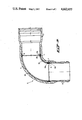
- FIG. 3 illustrates a bend 11 obtained by applying a connection according to the invention.
- a thinwalled centering pipe portion 7 in the form of a socket having an abutment collar 9 is accommodated the end portion 12a of a pipe part 12, said end portion 12a having a reduced wall thickness, a glue layer extending between said end portion and the inner side of the centering pipe portion 7.
- this second socket-shaped centering pipe portion 7 there is accommodated in this second socket-shaped centering pipe portion 7 the end portion 13a of a pipe part 13, said end portion having a reduced wall thickness.
- glue layers 5 and 6 between the outer side of end portion 13a of pipe part 13, the thinned end portion 18b of the bend 18 respectively and the inner side of the socket-shaped centering pipe portion 7.
- the pipe part 12 is a spigot end portion and the pipe part 13 a socket end portion.
- a reinforcing laminate layer 3 is wrapped around the bend and also extends to beyond the outer side of the socket end 13 and the outer side of the spigot end 12.
- FIG. 4 illustrates an additional modified embodiment of the connection according to the present invention.
- the centering pipe portion has the form of a thinwalled branch saddle portion.
- the wall of the first fibre reinforced plastic pipe part 15 is provided with a portion 15a having a reduced wall thickness, the recess formed at the outer side of pipe part portion 15a and provided on producing said pipe part portion, serving for accommodating the branch saddle portion 20.
- FIG. 4a illustrates the connection formed at the location of the thinned portion 15a; it should be noted that it is in certain cases preferable to provide the inner side of the branch saddle portion 20 with a shoulder 16, so as to obtain a reliable well-sealed connection.
- FIG. 4b showing a recess with its transitional surface 19 and formed by the portion 15a, serving to accommodate the edge of the branch saddle portion 20.
- a second fibre reinforced plastic pipe part 2 is accommodated in the saddle-shaped centering pipe portion 20, an adhesive layer then extending between the end portion of the second fibre reinforced plastic pipe part 2 and the inner side of the centering pipe portion 20.
- FIG. 5 shows a pipe connection according to the invention interconnecting a first and a second fibre reinforced plastic pipe 21, 22 respectively.
- the bend 28 has been formed by interconnecting a plurality of standard bent parts 28a-28e of e.g. 5° or 10°.
- Each standard bent part is a thinwalled fibre reinforced plastic bend part provided with an end widening 29 so that two consecutive bend parts 28a-28e are connected by means of a spigot-socket connection 30 and an adhesive layer 25 between the outer side of widening 29 and the opposite wall of penetrating bend part end portion 31.
- a thinned free end portion 22a of the second fibre reinforced plastic pipe 22 is accommodated in widening 29 of a standard bent part 18e.
- a thinned free end portion 21a of a first fibre reinforced plastic pipe part 21 is accommodated in one end of socket 27 of fibre reinforced plastic material and a free end portion 28a' of a bent part 28a is accommodated in the other end of the socket, an adhesive layer 25 connects the socket 27 with portion 28' and free end portion 21a.
- a reinforcing layer 23 has been wound around bend 28 and adjoining portions of plastic pipes 21 and 22.
- any desired bend can be formed. This simplifies the production of bends as no separate moulds are required for forming bends of different lengths and moreover simple moulds are sufficient for manufacturing said standard bent parts. At last these standard bent parts can be produced at low costs as they can be manufactured by an automatic winding process in contrast to the long integral bends as presently used.
Abstract
A pipe connection of a first and a second fibre reinforced plastic pipe by accommodating a free end portion of each pipe in a centering plastic pipe part, an adhesive layer being present between the inner side of the centering pipe part and the outer side of the free end portions. A reinforcing layer extends over the centering pipe part and over parts of the first and second pipe part adjoining the free ends of the centering pipe part, preferably the centering pipe part has a smaller wall thickness than the wall thickness of the first and second pipe parts.
The free end portions have a smaller wall thickness than the wall thickness of the centering pipe part.
The centering pipe part may be formed as a bend, or part of a saddle or branch saddle and consists of a reinforced thermosetting plastic material.
The bend may be formed from a plurality of standard bend parts of relatively small length, e.g. 5° or 10°, each having an end widening and a bend part end portion of a consecutive bend part penetrating into said widened end, an adhesive layer engaging said penetrating bend part end portion and the opposite inner wall of the widening.
The fibre reinforced plastic pipes, the centering pipe part and the reinforcing layer all consist of thermosetting resin.
Description
This invention relates to a pipe connection interconnecting a first fibre reinforced plastic pipe part and a second fibre reinforced plastic pipe part, comprising an adhesive connection between the two pipe parts and a reinforcing layer, extending over the adhesive connection, and over the pipe part portions adjoining the adhesive connection and cooperating with same.
A pipe connection of this type, consisting of a first fibre reinforced plastic pipe part interconnected with a second fibre reinforced plastic pipe part consisting of a thermosetting resin, e.g. epoxy resin and comprising an adhesive connection is known in the art.
To obtain such a connection a first and second fibre reinforced plastic pipe part are sawn off in a straight manner or if curves are to be made preferably mitre sawn, whereupon the front end portions so obtained are placed opposite each other and the slit between said front end portions is subsequently filled with a filler glue or resin whether reinforced by means of a fibrous web or not. To obtain the desired strength of the obtained connection a laminate layer of a fibre reinforced thermosetting resin is wrapped around the outer side of the end portion of the first fibre reinforced plastic pipe part and around the opposite end portion of the second fibre reinforced plastic pipe part.
However, several disadvantages may arise with regard to such a connection and the production thereof:
(a) firstly it is very difficult to accurately saw off the end portions of the two pipe parts, especially in case mitre sawn pipe end portions are desired;
(b) the fibre reinforced filler glue or resin for filling the slit between the two plastic pipe parts to be interconnected, does not always adhere satisfactorily, so that leakages might take place in a pipe conduit,
(c) between the free end portions of the fibre reinforced plastic pipe parts and the laminate layer wrapped around them delamination may easily occur,
(d) especially in the event of greater pipe diameters it is extremely difficult to accurately place the front end portions of the first and second fibre reinforced plastic pipe parts to be interconnected, opposite each other, thus enhancing the risk of future leakages occurring.
The present invention aims to provide a pipe connection of the kind as described above by means of which said disadvantages are overcome, while, more particularly, it is ensured that a reliable seal of the connection will be obtained.
This object is attained according to the invention in that a free end portion of the first fibre reinforced plastic pipe part and a free end portion of the second fibre reinforced plastic pipe part are accommodated in a centering pipe portion, the adhesive connection at least extending between the free end portions of the first and the second plastic pipe part and the centering pipe portion.
The use of such a centering pipe portion will result in an optimum adhesive connection between the first fibre reinforced plastic pipe part and the second fibre reinforced plastic pipe part, ensuring a very reliable seal. In addition the first and second fibre reinforced plastic pipe part to be interconnected can easily be centered in the correct manner, so that the strength of the adhesive connection is improved in this manner too.
Moreover mitre sawing plastic pipe parts to obtain a curve has thereby become redundant.
In an advantageous embodiment at least one side of the centering pipe portion is provided with an internal abutment surface, so that an optimum centering action is guaranteed, especially when the abutment surface is an annular abutment collar.
Very advantageously the wall thickness of the free end portions of the first and second fibre reinforced plastic pipe parts is smaller than that of the portions adjoining them so that in the finished connection the outer diameter of the centering pipe portion may correspond to the outer diameter of the first and second fibre reinforced plastic pipe part, a laminate connection of a homogeneous thickness resulting therefrom, when applying a laminate layer. Said features all contribute to obtaining a very reliable seal between the two plastic pipe parts.
According to a preferred embodiment the centering pipe portion is a thinwalled socket pipe portion.
The centering pipe portion may also advantageously be a bend, the reinforcing layer then extending over the end portions of the first and second plastic pipe part and over the aforementioned bend.
In case the centering pipe portion is provided with an abutment collar, the inner diameter of the said collar substantially corresponds to the inner diameter of the first and second plastic pipe part.
FIG. 1a is a connection of a first fibre reinforced plastic pipe part and a second fibre reinforced plastic pipe part, according to the state of art;
FIG. 1b is a connection of a first fibre reinforced plastic pipe part with a second fibre reinforced plastic pipe part, according to the present invention;
FIG. 2 is, according to the invention, a connection when forming a bend in a conduit;
FIG. 3 is a bend comprising connections according to the invention;
FIG. 4 is, according to the invention, a connection as used in the case of a branch saddle portion;
FIG. 4a is a detail of FIG. 4;
FIG. 4b is a modified method of interconnecting a pipe portion with a branch saddle portion;
FIG. 5 shows a modified bend in a connection according to the invention;
FIG. 5a shows a part of the modified bend according to FIG. 5, at the connection with the first fibre reinforced plastic pipe part;
FIG. 5b shows a part of the modified bend according to FIG. 5 at the connection with the second fibre reinforced plastic pipe part.
FIG. 1a illustrates a connection, known per se, of a first fibre reinforced plastic pipe part 1 with a second fibre reinforced plastic pipe part 2, the front end portions 1', 2' of the two fibre reinforced plastic pipe parts being placed opposite each other so that a slit is otained, filled with a filler glue or resin whether or not reinforced by a fibrous web. The pipes 1 and 2 consist of polyester or epoxy resin reinforced by glass filaments.
To obtain the required connecting strength a reinforcing layer 3 in the form of a laminate layer, is wrapped around the outer side of the first fibre reinforced plastic pipe part 1 and the outer side of the second fibre reinforced plastic pipe part 2.
Said known connection is disadvantageous in that its seal is inappropriate because of the difficulties arising when trying to correctly place opposite each other the front ends of the fibre reinforced plastic pipe parts 1 and 2; in addition an optimum adherence of the filler glue or resin to the pipe parts cannot be obtained.
FIG. 1b illustrates a connection according to the invention, comprising a first fibre reinforced plastic pipe part 1 of polyester resin and a second fibre reinforced plastic pipe part 2 of polyester resin, provided with pipe end portions 1a, 2a respectively, the wall thickness of same being smaller than the wall thickness of the parts adjoining them, said end portions being accommodated in a centering pipe portion 7 in the form of a thinwalled socket comprising an annular abutment collar.
A good connection and seal are ensured by means of an annular glue layer 6 between the end portion 1a and the centering pipe portion 7. In the same manner an annular glue layer 5 connects the end portion 2a with the other side of the centering pipe portion 7. A laminate layer 3 is wrapped around the outer side of the centering pipe portion 7 and the adjoining portions of the two plastic pipe parts 1 and 2.
In this manner an optimum tight connection is obtained between the centering pipe portion 7 and the plastic pipe parts 1 and 2. The inner diameter of the inner wall 9a of the collar 9 of the centering pipe portion 7 substantially corresponds to the inner diameter of the first and second fibre reinforced plastic pipe part 1, 2.
FIG. 2 illustrates a bend connection 10 between a first fibre reinforced plastic pipe part 1 and a second fibre reinforced plastic pipe part 2. Both fibre reinforced plastic pipe parts 1, 2 are provided with end portions having a reduced wall thickness and being accommodated in the centering pipe portion 7, in this case having the form of a bend. The connection between the centering pipe portion 7 having the form of a bend and the end portions 1a, 2a resp. of the fibre reinforced plastic pipe parts 1, 2 is obtained in a manner corresponding to the one illustrated in FIG. 1b, to wit by means of annular glue layers 6, 5 resp.
A laminate layer 3 is wrapped around the centering pipe portion 7 in the form of a bend, said laminate layer extending upon the outer side of the first fibre reinforced plastic pipe part 1 and upon the outer side of the second fibre reinforced plastic pipe part 2.
FIG. 3 illustrates a bend 11 obtained by applying a connection according to the invention. In a thinwalled centering pipe portion 7 in the form of a socket having an abutment collar 9 is accommodated the end portion 12a of a pipe part 12, said end portion 12a having a reduced wall thickness, a glue layer extending between said end portion and the inner side of the centering pipe portion 7.
On the other hand there is accommodated in and adhered by means of an adhesive to the socket-shaped centering pipe portion 7, the end portion 18a of a fibre reinforced bend 18, said end portion also having a reduced wall thickness.
The other side of the bend 18, also being provided with an end portion 18b with a reduced wall thickness, is accommodated in a second socket-shaped centering pipe portion 7 comprising an abutment collar 9.
On the other hand there is accommodated in this second socket-shaped centering pipe portion 7 the end portion 13a of a pipe part 13, said end portion having a reduced wall thickness. In this case too there are provided glue layers 5 and 6 between the outer side of end portion 13a of pipe part 13, the thinned end portion 18b of the bend 18 respectively and the inner side of the socket-shaped centering pipe portion 7.
In FIG. 3 the pipe part 12 is a spigot end portion and the pipe part 13 a socket end portion.
A reinforcing laminate layer 3 is wrapped around the bend and also extends to beyond the outer side of the socket end 13 and the outer side of the spigot end 12.
Due to the above features finally the bend 11 is obtained.
FIG. 4 illustrates an additional modified embodiment of the connection according to the present invention.
The centering pipe portion has the form of a thinwalled branch saddle portion.
The wall of the first fibre reinforced plastic pipe part 15 is provided with a portion 15a having a reduced wall thickness, the recess formed at the outer side of pipe part portion 15a and provided on producing said pipe part portion, serving for accommodating the branch saddle portion 20.
FIG. 4a illustrates the connection formed at the location of the thinned portion 15a; it should be noted that it is in certain cases preferable to provide the inner side of the branch saddle portion 20 with a shoulder 16, so as to obtain a reliable well-sealed connection.
Obviously it is also possible to obtain a proper connection as illustrated in FIG. 4b, showing a recess with its transitional surface 19 and formed by the portion 15a, serving to accommodate the edge of the branch saddle portion 20.
In addition a second fibre reinforced plastic pipe part 2 is accommodated in the saddle-shaped centering pipe portion 20, an adhesive layer then extending between the end portion of the second fibre reinforced plastic pipe part 2 and the inner side of the centering pipe portion 20.
FIG. 5 shows a pipe connection according to the invention interconnecting a first and a second fibre reinforced plastic pipe 21, 22 respectively.
The bend 28 has been formed by interconnecting a plurality of standard bent parts 28a-28e of e.g. 5° or 10°. Each standard bent part is a thinwalled fibre reinforced plastic bend part provided with an end widening 29 so that two consecutive bend parts 28a-28e are connected by means of a spigot-socket connection 30 and an adhesive layer 25 between the outer side of widening 29 and the opposite wall of penetrating bend part end portion 31.
A thinned free end portion 22a of the second fibre reinforced plastic pipe 22 is accommodated in widening 29 of a standard bent part 18e.
A thinned free end portion 21a of a first fibre reinforced plastic pipe part 21 is accommodated in one end of socket 27 of fibre reinforced plastic material and a free end portion 28a' of a bent part 28a is accommodated in the other end of the socket, an adhesive layer 25 connects the socket 27 with portion 28' and free end portion 21a.
A reinforcing layer 23 has been wound around bend 28 and adjoining portions of plastic pipes 21 and 22.
Starting from equal standard bent parts 28a-28e of e.g. 10° any desired bend can be formed. This simplifies the production of bends as no separate moulds are required for forming bends of different lengths and moreover simple moulds are sufficient for manufacturing said standard bent parts. At last these standard bent parts can be produced at low costs as they can be manufactured by an automatic winding process in contrast to the long integral bends as presently used.
Claims (6)
1. A pipe connection interconnecting a first fibre reinforced plastic pipe part and a second fibre reinforced plastic pipe part, the wall thickness of the free end portions of the first and second pipe part being smaller in outer diameter than the portions adjoining them, comprising an adhesive connection between the two pipe parts and a reinforcing layer being formed by wrappping a laminate with with thermosetting resin around the connection and extending over the adhesive connection and over the pipe part portions adjoining the adhesive connection, and cooperating with same, said adhesive connection comprising a centering pipe portion of fibre reinforced plastic materials accommodating a free end portion of the first and second fibre reinforced plastic pipe parts, said centering pipe portion extending over the outer side of said free end portions and being connected to said free end portions solely by means of an adhesive layer between said centering pipe portion and said free end portions and said centering pipe portion having a maximum wall thickness which is substantially smaller than the wall thickness of the first and second pipe parts, at least one side of the centering pipe portion being provided with an internal abutment surface, the internal diameter of said abutment surface substantially corresponding to the inner diameter of said first and the second pipe part.
2. A pipe connection according to claim 1, wherein the centering pipe portion is a socket-shaped centering pipe portion.
3. A pipe connection according to claim 1, wherein the centering pipe portion is a bend.
4. A pipe connection according to claim 1, wherein a centering pipe portion forms a branch saddle portion.
5. A pipe connection according to claim 1 further comprising a bend formed by a plurality of interconnected bend parts, each bend part having a widened end engaged by an adhesive layer, a free end portion of an adjacent bend part penetrating into said widened end.
6. A pipe connection according to claim 5, comprising a plurality of equal interconnected bend parts of a relatively small length.
Applications Claiming Priority (2)
| Application Number | Priority Date | Filing Date | Title |
|---|---|---|---|
| NL8303190A NL8303190A (en) | 1983-09-15 | 1983-09-15 | TUBE CONNECTION OF FIBER-REINFORCED PLASTIC TUBES. |
| NL8303190 | 1983-09-15 |
Publications (1)
| Publication Number | Publication Date |
|---|---|
| US4662655A true US4662655A (en) | 1987-05-05 |
Family
ID=19842409
Family Applications (1)
| Application Number | Title | Priority Date | Filing Date |
|---|---|---|---|
| US06/650,460 Expired - Fee Related US4662655A (en) | 1983-09-15 | 1984-09-14 | Pipe connection of fibre reinforced plastic pipe parts |
Country Status (6)
| Country | Link |
|---|---|
| US (1) | US4662655A (en) |
| EP (1) | EP0141450B1 (en) |
| JP (1) | JPS60121390A (en) |
| AT (1) | ATE34604T1 (en) |
| DE (1) | DE3471517D1 (en) |
| NL (1) | NL8303190A (en) |
Cited By (21)
| Publication number | Priority date | Publication date | Assignee | Title |
|---|---|---|---|---|
| US5131688A (en) * | 1990-12-28 | 1992-07-21 | Coupling Systems, Inc. | Pipe insulator and method for making same |
| US5163713A (en) * | 1989-05-03 | 1992-11-17 | Fusion Group Plc | Electro-fusion fittings |
| US5228186A (en) * | 1989-05-03 | 1993-07-20 | Fusion Plastics Ltd. | Method of manufacturing electro-fusion fittings |
| US5421781A (en) * | 1992-04-03 | 1995-06-06 | Turboflex Limited | Couplings |
| US5527130A (en) * | 1992-02-19 | 1996-06-18 | Environ Products, Inc. | Environmentally safe underground piping system |
| US5547230A (en) * | 1995-04-28 | 1996-08-20 | The Lamson & Sessions Co. | Joint for variable wall thickness conduit |
| US5730472A (en) * | 1993-10-29 | 1998-03-24 | The Dow Chemical Company | Flangeless pipe joint and a process for manufacturing such a joint |
| US5782500A (en) * | 1995-05-26 | 1998-07-21 | Mate; Robert James | Passageway aligned coupling and process |
| US5865216A (en) | 1995-11-08 | 1999-02-02 | Advanced Polymer Technology, Inc. | System for housing secondarily contained flexible piping |
| US6148581A (en) * | 1997-04-22 | 2000-11-21 | Dr. Ing. H.C.F. Porsche Ag | Internal high pressure formed nodal connection element for a frame construction, and method of making same |
| US6176523B1 (en) | 1997-03-12 | 2001-01-23 | The Lamson & Sessions Co. | Joint for variable wall thickness conduit |
| USRE37114E1 (en) | 1993-11-01 | 2001-03-27 | Advanced Polymer Technology, Inc. | Secondary containment flexible underground piping system |
| US20080210309A1 (en) * | 2007-03-01 | 2008-09-04 | Randy Tan | Diverter valve |
| US20090243284A1 (en) * | 2008-03-18 | 2009-10-01 | Saint-Gobain Performance Plastics Corpration | Fluid Transfer Assemblies and Related Methods |
| US20100187813A1 (en) * | 2009-01-23 | 2010-07-29 | Anders Richard M | Connector for Interconnecting A Lateral Pipe to A Main Pipe |
| US20130056937A1 (en) * | 2010-04-28 | 2013-03-07 | Markus Watermann | Sealing Collar |
| US20150323104A1 (en) * | 2014-05-12 | 2015-11-12 | Hawkeye Concrete Products Co. | Reinforced concrete pipe |
| US20170314724A1 (en) * | 2015-08-08 | 2017-11-02 | Zhaohui Zhou | Auto-fill two-layer two-half wear resistant elbow of concrete pump truck and manufacturing method thereof |
| US11754215B2 (en) | 2020-07-20 | 2023-09-12 | Saudi Arabian Oil Company | Apparatus and method for friction welding of reinforced thermosetting resin pipe joints |
| US11761571B2 (en) | 2020-07-20 | 2023-09-19 | Saudi Arabian Oil Company | Apparatus and method for electrofusion welding of reinforced thermosetting resin pipe joints |
| US11794418B2 (en) | 2020-07-20 | 2023-10-24 | Saudi Arabian Oil Company | Apparatus and method for threaded-welded reinforced thermosetting resin pipe joints |
Families Citing this family (3)
| Publication number | Priority date | Publication date | Assignee | Title |
|---|---|---|---|---|
| EP0612953A1 (en) * | 1993-02-22 | 1994-08-31 | Streng Plastic AG | Connector for tubular plastic parts |
| CN102401202B (en) * | 2011-11-02 | 2013-05-08 | 中联重科股份有限公司 | Pipe clamp and connecting structure of fluid conveying pipeline |
| DE102022101796A1 (en) | 2022-01-26 | 2023-07-27 | Basf Se | Method of connecting composite pipes |
Citations (12)
| Publication number | Priority date | Publication date | Assignee | Title |
|---|---|---|---|---|
| US1706525A (en) * | 1926-05-17 | 1929-03-26 | Elmer E Gullion | Sheet-metal pipe |
| US2234643A (en) * | 1939-09-06 | 1941-03-11 | American Concrete And Steel Pi | Pipe joint for concrete pipe |
| US2785910A (en) * | 1955-05-05 | 1957-03-19 | Amercoat Corp | Molded joint for plastic tubes with latch |
| US3053724A (en) * | 1957-01-31 | 1962-09-11 | Porter Co Inc H K | Method of splicing sections of heavy duty discharge hose |
| US3744823A (en) * | 1971-03-01 | 1973-07-10 | Shaw Pipe Ind Ltd | High temperature pipeline joints |
| JPS49614A (en) * | 1972-04-17 | 1974-01-07 | ||
| US3977704A (en) * | 1976-01-12 | 1976-08-31 | Westinghouse Electric Corporation | Pipe coupler |
| US4011652A (en) * | 1976-04-29 | 1977-03-15 | Psi Products, Inc. | Method for making a pipe coupling |
| US4147381A (en) * | 1976-07-23 | 1979-04-03 | Walter Schwarz | Pipe coupling |
| DE2911714A1 (en) * | 1979-03-24 | 1980-10-02 | Mtu Motorn Und Turbinen Union | METHOD FOR PRODUCING HIGH-TEMPERATURE-RESISTANT METAL COMPONENTS WITH FINE-POROUS WALLS |
| US4398754A (en) * | 1980-08-11 | 1983-08-16 | Kerotest Manufacturing Corp. | Electrically insulated pipe coupling and method for making the same |
| US4514244A (en) * | 1981-09-21 | 1985-04-30 | Nibco Inc. | Plastic pipe elements and methods for making same |
Family Cites Families (7)
| Publication number | Priority date | Publication date | Assignee | Title |
|---|---|---|---|---|
| US1919734A (en) * | 1931-01-24 | 1933-07-25 | Line Material Co | Conduit |
| GB695027A (en) * | 1950-08-15 | 1953-08-05 | Raymond James Mitchell | Improvements in or relating to connecting means for pipes and tubes |
| GB881428A (en) * | 1957-09-30 | 1961-11-01 | Amercoat Corp | Coupling for plastic pipe |
| FR1357775A (en) * | 1963-02-27 | 1964-04-10 | Gaillon Soc Ind De | Process for making elbows, in plastic pipes, and tubular elements for carrying out this process |
| DE7101299U (en) * | 1970-01-16 | 1971-06-03 | Soc Del Gres Ing Sala & C Spa | Device for the production of branches in pipelines made of plastic material |
| US4165104A (en) * | 1973-04-27 | 1979-08-21 | Wavin B.V. | Sealed joint pipe connection |
| JPS581536B2 (en) * | 1977-07-02 | 1983-01-11 | 富士通株式会社 | Manufacturing method of solid electrolytic capacitor |
-
1983
- 1983-09-15 NL NL8303190A patent/NL8303190A/en not_active Application Discontinuation
-
1984
- 1984-09-13 EP EP84201331A patent/EP0141450B1/en not_active Expired
- 1984-09-13 AT AT84201331T patent/ATE34604T1/en not_active IP Right Cessation
- 1984-09-13 DE DE8484201331T patent/DE3471517D1/en not_active Expired
- 1984-09-14 US US06/650,460 patent/US4662655A/en not_active Expired - Fee Related
- 1984-09-14 JP JP59191871A patent/JPS60121390A/en active Pending
Patent Citations (12)
| Publication number | Priority date | Publication date | Assignee | Title |
|---|---|---|---|---|
| US1706525A (en) * | 1926-05-17 | 1929-03-26 | Elmer E Gullion | Sheet-metal pipe |
| US2234643A (en) * | 1939-09-06 | 1941-03-11 | American Concrete And Steel Pi | Pipe joint for concrete pipe |
| US2785910A (en) * | 1955-05-05 | 1957-03-19 | Amercoat Corp | Molded joint for plastic tubes with latch |
| US3053724A (en) * | 1957-01-31 | 1962-09-11 | Porter Co Inc H K | Method of splicing sections of heavy duty discharge hose |
| US3744823A (en) * | 1971-03-01 | 1973-07-10 | Shaw Pipe Ind Ltd | High temperature pipeline joints |
| JPS49614A (en) * | 1972-04-17 | 1974-01-07 | ||
| US3977704A (en) * | 1976-01-12 | 1976-08-31 | Westinghouse Electric Corporation | Pipe coupler |
| US4011652A (en) * | 1976-04-29 | 1977-03-15 | Psi Products, Inc. | Method for making a pipe coupling |
| US4147381A (en) * | 1976-07-23 | 1979-04-03 | Walter Schwarz | Pipe coupling |
| DE2911714A1 (en) * | 1979-03-24 | 1980-10-02 | Mtu Motorn Und Turbinen Union | METHOD FOR PRODUCING HIGH-TEMPERATURE-RESISTANT METAL COMPONENTS WITH FINE-POROUS WALLS |
| US4398754A (en) * | 1980-08-11 | 1983-08-16 | Kerotest Manufacturing Corp. | Electrically insulated pipe coupling and method for making the same |
| US4514244A (en) * | 1981-09-21 | 1985-04-30 | Nibco Inc. | Plastic pipe elements and methods for making same |
Cited By (27)
| Publication number | Priority date | Publication date | Assignee | Title |
|---|---|---|---|---|
| US5163713A (en) * | 1989-05-03 | 1992-11-17 | Fusion Group Plc | Electro-fusion fittings |
| US5228186A (en) * | 1989-05-03 | 1993-07-20 | Fusion Plastics Ltd. | Method of manufacturing electro-fusion fittings |
| US5131688A (en) * | 1990-12-28 | 1992-07-21 | Coupling Systems, Inc. | Pipe insulator and method for making same |
| US5527130A (en) * | 1992-02-19 | 1996-06-18 | Environ Products, Inc. | Environmentally safe underground piping system |
| US5421781A (en) * | 1992-04-03 | 1995-06-06 | Turboflex Limited | Couplings |
| US5665187A (en) * | 1992-04-03 | 1997-09-09 | Turboflex Limited | Method for connecting composite drive shaft to annular member |
| US5730472A (en) * | 1993-10-29 | 1998-03-24 | The Dow Chemical Company | Flangeless pipe joint and a process for manufacturing such a joint |
| USRE37114E1 (en) | 1993-11-01 | 2001-03-27 | Advanced Polymer Technology, Inc. | Secondary containment flexible underground piping system |
| US5547230A (en) * | 1995-04-28 | 1996-08-20 | The Lamson & Sessions Co. | Joint for variable wall thickness conduit |
| US5782500A (en) * | 1995-05-26 | 1998-07-21 | Mate; Robert James | Passageway aligned coupling and process |
| US5865216A (en) | 1995-11-08 | 1999-02-02 | Advanced Polymer Technology, Inc. | System for housing secondarily contained flexible piping |
| US6176523B1 (en) | 1997-03-12 | 2001-01-23 | The Lamson & Sessions Co. | Joint for variable wall thickness conduit |
| US6148581A (en) * | 1997-04-22 | 2000-11-21 | Dr. Ing. H.C.F. Porsche Ag | Internal high pressure formed nodal connection element for a frame construction, and method of making same |
| US7849877B2 (en) | 2007-03-01 | 2010-12-14 | Zodiac Pool Systems, Inc. | Diverter valve |
| US20080210309A1 (en) * | 2007-03-01 | 2008-09-04 | Randy Tan | Diverter valve |
| US8910662B2 (en) | 2007-03-01 | 2014-12-16 | Zodiac Pool Systems, Inc. | Diverter valve |
| US9259563B2 (en) * | 2008-03-18 | 2016-02-16 | Saint-Gobain Performance Plastics Corporation | Fluid transfer assemblies and related methods |
| US20090243284A1 (en) * | 2008-03-18 | 2009-10-01 | Saint-Gobain Performance Plastics Corpration | Fluid Transfer Assemblies and Related Methods |
| US20100187813A1 (en) * | 2009-01-23 | 2010-07-29 | Anders Richard M | Connector for Interconnecting A Lateral Pipe to A Main Pipe |
| US20130056937A1 (en) * | 2010-04-28 | 2013-03-07 | Markus Watermann | Sealing Collar |
| US20150323104A1 (en) * | 2014-05-12 | 2015-11-12 | Hawkeye Concrete Products Co. | Reinforced concrete pipe |
| US10563794B2 (en) * | 2014-05-12 | 2020-02-18 | Fsc Technologies, Llc | Reinforced concrete pipe |
| US20170314724A1 (en) * | 2015-08-08 | 2017-11-02 | Zhaohui Zhou | Auto-fill two-layer two-half wear resistant elbow of concrete pump truck and manufacturing method thereof |
| US10428994B2 (en) * | 2015-08-08 | 2019-10-01 | Zhaohui Zhou | Auto-fill two-layer two-half wear resistant elbow of concrete pump truck and manufacturing method thereof |
| US11754215B2 (en) | 2020-07-20 | 2023-09-12 | Saudi Arabian Oil Company | Apparatus and method for friction welding of reinforced thermosetting resin pipe joints |
| US11761571B2 (en) | 2020-07-20 | 2023-09-19 | Saudi Arabian Oil Company | Apparatus and method for electrofusion welding of reinforced thermosetting resin pipe joints |
| US11794418B2 (en) | 2020-07-20 | 2023-10-24 | Saudi Arabian Oil Company | Apparatus and method for threaded-welded reinforced thermosetting resin pipe joints |
Also Published As
| Publication number | Publication date |
|---|---|
| JPS60121390A (en) | 1985-06-28 |
| EP0141450B1 (en) | 1988-05-25 |
| ATE34604T1 (en) | 1988-06-15 |
| DE3471517D1 (en) | 1988-06-30 |
| EP0141450A1 (en) | 1985-05-15 |
| NL8303190A (en) | 1985-04-01 |
Similar Documents
| Publication | Publication Date | Title |
|---|---|---|
| US4662655A (en) | Pipe connection of fibre reinforced plastic pipe parts | |
| US4722717A (en) | End connection for composite shafts | |
| US6361080B1 (en) | Method for attaching an ANSI stub-end flanged connector to a composite tubular member | |
| US4200605A (en) | Production of reinforced plastic pipes | |
| US3388932A (en) | Joint for laminated articles | |
| JPS62110094A (en) | Flange connector for fiber reinforced plastic pipe section | |
| FI68717C (en) | FLAENSFOERSEDD ROERDEL | |
| US4217935A (en) | Fiber reinforced plastic pipe part | |
| US4269234A (en) | High strength pipe | |
| US3468346A (en) | Pipe fittings having an inner thermoplastic surface and an outer thermoset surface | |
| US5091230A (en) | Tube of composite material with a fibrous thermoplastic coating and process for manufacturing such a tube | |
| KR101991723B1 (en) | Method for manufacturing fibre reinforced plastic pipe | |
| EP0423196B1 (en) | Composite thread coupling for reinforced pipe | |
| JPS643035Y2 (en) | ||
| JPS6271614A (en) | Manufacture of lining hume pipe | |
| US6478921B1 (en) | Method for producing ends of metal of composite pipe lengths | |
| JPH11101383A (en) | Connecting structure of polyethylene resin pipe and connection method | |
| FI70081C (en) | KOPPLING FOER ROER FOERSETT MED YTSKIKT AV HAORDPLAST FOERFARANDE FOER FRAMSTAELLNING AV KOPPLINGEN OCH VERKTYG FOER FOERVERKLIGANDE AV FOERFARANDET | |
| JP2561194Y2 (en) | Plastic tube joint structure | |
| JP2005090595A (en) | Electric fusion joint, and method for manufacturing the same | |
| JPS5896515A (en) | Method of joining metal joint to pipe | |
| KR950008468B1 (en) | Method for manufacturing coupling flange for plastic pipe and the same | |
| JP2996273B2 (en) | Structure of piping for piping into a tunnel with curvature | |
| JPS58215310A (en) | Jointing method of metal pipe and fiber reinforced synthetic resin pipe | |
| KR950008469B1 (en) | Method for manufacturing coupling flange for plastic pipe and the same |
Legal Events
| Date | Code | Title | Description |
|---|---|---|---|
| AS | Assignment |
Owner name: WAVIN B.V., 251 HANDELLAAN, 8031 EM ZWOLLE, THE NE Free format text: ASSIGNMENT OF ASSIGNORS INTEREST.;ASSIGNORS:FLIERVOET, JOHANNES H. M.;OFFRINGA, OEGE R.;REEL/FRAME:004311/0831 Effective date: 19840903 |
|
| FPAY | Fee payment |
Year of fee payment: 4 |
|
| REMI | Maintenance fee reminder mailed | ||
| LAPS | Lapse for failure to pay maintenance fees | ||
| FP | Lapsed due to failure to pay maintenance fee |
Effective date: 19950510 |
|
| STCH | Information on status: patent discontinuation |
Free format text: PATENT EXPIRED DUE TO NONPAYMENT OF MAINTENANCE FEES UNDER 37 CFR 1.362 |