US4655080A - Dynamic tire balancing machine and method - Google Patents
Dynamic tire balancing machine and method Download PDFInfo
- Publication number
- US4655080A US4655080A US06/782,992 US78299285A US4655080A US 4655080 A US4655080 A US 4655080A US 78299285 A US78299285 A US 78299285A US 4655080 A US4655080 A US 4655080A
- Authority
- US
- United States
- Prior art keywords
- tire
- wheel
- axle
- road wheel
- balancing machine
- Prior art date
- Legal status (The legal status is an assumption and is not a legal conclusion. Google has not performed a legal analysis and makes no representation as to the accuracy of the status listed.)
- Expired - Fee Related
Links
Images


Classifications
-
- G—PHYSICS
- G01—MEASURING; TESTING
- G01M—TESTING STATIC OR DYNAMIC BALANCE OF MACHINES OR STRUCTURES; TESTING OF STRUCTURES OR APPARATUS, NOT OTHERWISE PROVIDED FOR
- G01M1/00—Testing static or dynamic balance of machines or structures
- G01M1/14—Determining unbalance
- G01M1/16—Determining unbalance by oscillating or rotating the body to be tested
- G01M1/22—Determining unbalance by oscillating or rotating the body to be tested and converting vibrations due to unbalance into electric variables
- G01M1/225—Determining unbalance by oscillating or rotating the body to be tested and converting vibrations due to unbalance into electric variables for vehicle wheels
Definitions
- This invention relates to the balancing of rubber tires, and has to do more particularly with a system for dynamically balancing the tires under conditions simulating those encountered by the tire when in use on a vehicle.
- Tires are supported by the roadway in much the same manner as a track supports a railroad wheel, but the railroad wheel is made of steel and is inflexible for practical purposes.
- the perimeter of the railroad wheel is machined so as to be concentric with its axis of rotation and therefore contacts the rail at a constant loaded radius.
- Tires are pneumatic annular envelopes intended to reduce shock while flexing at the footprint or tire patch, i.e., the area of the tire in contact with the roadway.
- a tire by reason of the nature of its construction is not symmetrical and therefore the balancing techniques utilized to balance a railroad wheel or an armature or a crankshaft are ineffective to properly balance a rubber tire.
- the balancing machine of the present invention comprises a road wheel adapted to be driven by a motor and a tire mounting system designed to maintain the tire and road wheel axles parallel despite vertical movement of the tire.
- the tire mounting system incorporates means to spring load the tire against the road wheel to simulate the weight load which will be borne by the tire in use as well as simulate the spring system of the vehicle which permits the wheel axle to move under the influence of asymmetrical forces.
- the tire mounting system includes a set of sensors positioned to sense the horizontal forces generated by the tire, i.e., the tangential forces developed at the footprint of the tire due to lack of centrifugally loaded tire symmetry.
- An additional sensor is positioned to measure the vertically generated forces, i.e, the forces indicating lack of symmetry at the rolling footprint.
- An optical encoder of known construction is incorporated in the wheel supporting hub mounted on the wheel axle which provides the angular locations of the vibratory forces. The measurements taken by the sensors and encoder are preferably fed to a pre-programmed computer which analyzes the data and determines the correct amount and proper location at which to place the corrective weights needed to overcome the vibratory forces within the tire.
- FIG. 1 is a perspective view of a tire balancing machine in accordance with the present invention.
- FIG. 2 is a top plan view of the tire balancing machine.
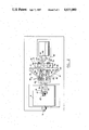
- FIG. 3 is a side elevational view thereof.
- FIG. 4 is an enlarged vertical sectional view of the spring assembly utilized to load the tire.
- the balancing machine comprises a main frame 1 having journals 2 and 3 which rotatably mount a road wheel 4 having an axle 5 adapted to be driven by a prime mover 6, which may comprise either an electric or an hydraulic motor, the prime mover driving the road wheel through a drive shaft 7 and universal joints 8, 9.
- a prime mover 6 which may comprise either an electric or an hydraulic motor, the prime mover driving the road wheel through a drive shaft 7 and universal joints 8, 9.
- the tire mounting system mounts a tire 11 which, in the embodiment illustrated, comprises a racing tire.
- a pair of support posts 12, 13 extend vertically upwardly from the main frame 1, the support posts being interconnected at their uppermost ends by a bridge plate 14.
- the posts 12, 13 are surrounded by split quills 15, 16 which are slidable axially relative to the support posts, the quills mounting a vertically disposed support plate 17 from which the tire 11 is suspended in a manner to be described hereinafter.
- a pair of arms 18, 19 project rearwardly from the support plate 17 between the support posts 12, 13, the arms 18, 19 mounting a block 20 having a threaded opening therein which receives a threaded shaft 21 which projects upwardly through bridge plate 14 where it is provided with a crank handle 22 which may be used to rotate the threaded shaft 21, thereby raising and lowering the support plate 17 relative to the posts 12 and 13.
- the split quills 15, 16 are provided with sets of ears 23 interconnected by locking bolts 24 by means of which the quills may be clamped to the support posts when it is desired to immobilize the support plate 17.
- a front plate 25 is suspended from support plate 17 by means of pairs of upper arms 26 and a corresponding pair of lower arms 27, one end of each arm being pivotally connected to the support plate 17 and its opposite end pivotally connected to the front plate 25 by means of brackets 28 and pivot pins 29, the pairs of arms defining a parallelogram linkage permitting vertical movement of the front plate 25 relative to the support plate 17 while maintaining the plates in parallel planes relative to each other.
- the arms are interconnected by cross-braces 30 and by sets of laterally extending arms 31, 32, pivotally connected to support plate 17 at their outermost ends by means of additional brackets 28 and pivot pins 29, the inner ends of the laterally extending arms 31, 32 being fixedly secured to the arms 26, 27, respectively, adjacent their outermost ends.
- the laterally extending arms permit pivotal movement of the arms 26, 27 in a vertical plane, but restrain the arms against lateral movement.
- the front plate 25 mounts a rearwardly projecting, open-sided axle box 33 which terminates rearwardly in a block 34.
- the axle box is supported by the front plate 25 and is reinforced by a series of reinforcing ribs 35.
- a non-rotatable wheel axle 36 is supported by the front plate 25, the rear block 34 and a front block 37 mounted on the outboard side of front plate 25.
- the forward end of the non-rotatable axis 36 projects outwardly beyond block 37 where it rotatably mounts a hub 38 to which the tire mounting wheel 39 is secured, as by means of a nut 40, the hub being provided with wheel positioning lugs 41 and a threaded nut receiving portion 42.
- a pair of sensors 43, 44 such as piezo crystal load cells, are mounted on blocks 34 and 37, respectively, the sensors being horizontally disposed and positioned to sense horizontal signals generated by the lack of symmetry of the tire.
- the sensor 43 mounted on the rear block 34 will sense signals generated by the lack of symmetry on the outboard side of the tire, i.e., the outer half of the tire as viewed in FIGS. 1 and 3.
- the sensor 44 mounted on the front block 37 will sense the lack of symmetry on the inboard side of the tire, i.e., the side of the tire adjacent the front block 37.
- a third sensor 45 is mounted on the top of the axle box 33 where it will sense vertical asymmetrical forces generated at the footprint of the tire when in contact with the road wheel 4.
- An encoder E is mounted within the hub 38, the encoder providing an origin signal during each revolution of the tire and a plurality of angular signals which are utilized to determine the locations at which the vibratory forces occur.
- the encoder is of known construction, such as a Trump-Ross (Gould) or a Teledyne Gurley.
- the tire is loaded against the road wheel by means of an electromechanical acutator 46 which, as best seen in FIGS. 2 and 3, is pivotally mounted on the arms 18 and 19 which project rearwardly from support plate 17.
- the actuator 46 is also of known construction and may comprise a Duff-Norton electromechanical actuator having an axially displaceable power shaft 47.
- An actuating arm 48 is pivotally connected at 49 to a supporting arm 50 fixedly secured to support plate 17.
- a clevis 51 pivotally connects one end of actuating arm 48 to the power shaft 47 of actuator 46, and a clevis 52 connects the opposite end of the actuating arm to the spring assembly 53.
- the spring assembly 53 comprises a cylindrical housing 54 having a closed upper end 55 against which a helical spring 56 is seated. At its opposite end the spring 56 is contacted by an annular plate 57 secured to a rod 58 by means of nuts 59. The uppermost end of the rod 58 projects through an opening in the closed end 55 of the spring assembly where it terminates in a fitting 60 pivotally connected to the lower extremity of front plate 25 by means of a mounting ear and pivot pin (not shown).
- the tire 11 is first mounted on the wheel 39 and inflated to the pressure at which the tire is designed to operate, whereupon the wheel is mounted on the hub 38.
- the locking bolts 24 on the split quills 15, 16 are loosened to permit the quills to be raised or lowered, the tire mounting system being raised or lowered by means of the threaded shaft 21 and crank handle 22, the objective being to position the tire so that it contacts the road wheel 4.
- the locking bolts 24 are then tightened, thereby fixing the position of the wheel axle 36 relative to the road wheel 4. Once the proper location of the axle relative to the road wheel has been established for a given size tire, no further adjustment is required to balance additional tires of the same size.
- the actuator 46 is energized to apply the desired load to the tire.
- the power shaft 47 will move axially upwardly, thereby pivoting the actuator arm 48 about the pivot 49 in a counterclockwise direction, such movement, due to the clevis 52, causing the cylindrical housing 54 of the spring assembly 53 to move downwardly relative to annular plate 57 and rod 58, thereby compressing the helical spring 56 and hence exerting a loading force on the front plate 25 which, due to the parallelogram linkage, moves downwardly while maintaining the parallel relationship between the wheel axle 36 and the axle 5 of the road wheel.
- Such movement serves to load the tire against the road wheel, the applied load being selected to simulate the weight load which will be borne by the tire in normal use.
- the prime mover 6 is started and the road wheel and tire brought up to the desired speed at which the tire is to be balanced. For example, if the tire is being balanced for passenger car use to operate at a speed of 60 miles per hour, the road wheel will be rotated until that speed is reached. If the tire being balanced is intended for race car use, the speed will be much higher, for example 200 to 250 miles per hour.
- Second stage--A known trial weight is then applied to the wheel rim on the inner side of the tire at a specific location, preferably in alignment with the zero degrees or origin signal from the encoder, such weight being indicated at 61 in FIG. 3.
- the weight should be large enough to be effective, but not too large to damage the machine.
- the applied weight may be from 1/2 to 5 grams, depending upon the size of the tire.
- the machine is started and run at the same speed and under the same load as the first stage and the output of the sensors 43, 44 and 45 recorded along with their angular locations, whereupon the machine is again stopped.
- the recorded readings from the three stages are analyzed by the computer, which is programmed to compare the data and calculate the correct amounts and proper locations to place needed corrective weights on both sides of the wheel rims to counteract the asymmetrical forces generated at the footprint of the tire.
- the computer will compare the magnitude and angular location of the asymmetrical forces generated by the tire during the first stage, in which the tire is in "as is” condition, with the forces generated by the tire when a trial weight of known magnitude is applied to a fixed location first on one side of the tire and then on the other side of the tire, and from these readings will calculate and display the correct amounts and proper locations to place needed corrective weights on both sides of the rim to offset the asymmetrical forces generated by the tire.
- the computer Once the computer has in storage the data generated by a given size tire and wheel, additional tires of the same diameter mounted on similar wheels can be processed by recording only the data taken during the first stage, namely, when the tire is tested in the "as is” condition.
- the computer By utilizing the first stage or "as is” data, the computer will be used to determine the correct weight and proper location of the weights on both sides of the rim without the need for additional runs, i.e., without stages two and three, providing the speed of rotation of the tire and the load are the same.
- each different size tire will be analyzed in the three stages set forth above, but thereafter additional tires of the same size may be processed by subjecting them only to the first stage operation followed by a computer analysis and comparison of the "as is" data with the previously collected second and third stage data for tires of the same size.
- the vertical sensor 45 may be utilized to determine the effectiveness of the process on the rolling radius, the net result being to offset the vertical vibratory reactions which occur within the tire when operated at a given speed and under a given load, thereby balancing the tire under in-use conditions rather than as if it were freely rotating in space, as has heretofore been the practice.
Abstract
Description
Claims (15)
Priority Applications (1)
| Application Number | Priority Date | Filing Date | Title |
|---|---|---|---|
| US06/782,992 US4655080A (en) | 1985-10-02 | 1985-10-02 | Dynamic tire balancing machine and method |
Applications Claiming Priority (1)
| Application Number | Priority Date | Filing Date | Title |
|---|---|---|---|
| US06/782,992 US4655080A (en) | 1985-10-02 | 1985-10-02 | Dynamic tire balancing machine and method |
Publications (1)
| Publication Number | Publication Date |
|---|---|
| US4655080A true US4655080A (en) | 1987-04-07 |
Family
ID=25127847
Family Applications (1)
| Application Number | Title | Priority Date | Filing Date |
|---|---|---|---|
| US06/782,992 Expired - Fee Related US4655080A (en) | 1985-10-02 | 1985-10-02 | Dynamic tire balancing machine and method |
Country Status (1)
| Country | Link |
|---|---|
| US (1) | US4655080A (en) |
Cited By (16)
| Publication number | Priority date | Publication date | Assignee | Title |
|---|---|---|---|---|
| US4759217A (en) * | 1985-09-12 | 1988-07-26 | Facom | Process and apparatus for balancing a vehicle wheel |
| WO1990003561A1 (en) * | 1988-09-28 | 1990-04-05 | Dynabal Corporation | Simplified data input system for dynamic balancing machine and wheel diagnostic system |
| US4958290A (en) * | 1988-11-18 | 1990-09-18 | Accu Industries, Inc. | Balancer |
| US5103595A (en) * | 1990-05-14 | 1992-04-14 | Fmc Corporation | Apparatus and method for reducing vibration characteristics in a wheel rim and tire assembly |
| EP0671621A2 (en) * | 1994-03-07 | 1995-09-13 | BRIDGESTONE/FIRESTONE, Inc. | Portable tyre uniformity test machine |
| EP1033562A2 (en) * | 1999-03-03 | 2000-09-06 | Schenck RoTec GmbH | Procedure and device for reducing the vibrations provoked by a wheel-unit of a vehicle |
| US6286195B1 (en) * | 1998-03-06 | 2001-09-11 | Bridgestone Corporation | Method of assembling tire and wheel recording medium which records phase angle operating program at the time of assembling tire and wheel, and assembly tire and wheel unit |
| US6606902B2 (en) * | 2001-07-09 | 2003-08-19 | The Goodyear Tire & Rubber Company | Method of improving steering performance robustness utilizing stiffness non-uniformity in tire/wheel |
| US20060162470A1 (en) * | 2002-12-31 | 2006-07-27 | Otto Daniel P | Gauge resistant measurement system |
| US20070000322A1 (en) * | 2005-04-19 | 2007-01-04 | Gessler Richard J Jr | Tire balancing devices and methods |
| US20080034894A1 (en) * | 2006-08-08 | 2008-02-14 | Mts Systems Corporation | Transducer for a rotating body |
| US9132814B2 (en) * | 2012-09-18 | 2015-09-15 | Gm Global Technology Operationd Llc | Systems and methods for vibration mitigation in a vehicle |
| CN109290864A (en) * | 2018-11-10 | 2019-02-01 | 厦门大学嘉庚学院 | Small tyre processing unit (plant) and application method |
| CN110346085A (en) * | 2019-07-26 | 2019-10-18 | 芜湖职业技术学院 | A kind of full-automatic wheel balancing fixture |
| US20220316992A1 (en) * | 2021-04-01 | 2022-10-06 | Citic Dicastal Co., Ltd. | Loading system and test equipment for automobile chassis simulation road test |
| CN116296074A (en) * | 2023-05-17 | 2023-06-23 | 滨州盟威戴卡轮毂有限公司 | Automobile hub dynamic balance detection equipment |
Citations (5)
| Publication number | Priority date | Publication date | Assignee | Title |
|---|---|---|---|---|
| US3412615A (en) * | 1965-09-30 | 1968-11-26 | Gen Motors Corp | Method of controlling vibrations of wheel and tire assemblies |
| US3862570A (en) * | 1973-01-26 | 1975-01-28 | Ongaro Dynamics | Tire symmetry measuring method and system |
| US3991621A (en) * | 1975-08-29 | 1976-11-16 | Armbruster Joseph M | Rotatable vehicle wheel support for spin balancer |
| US4366707A (en) * | 1980-03-18 | 1983-01-04 | Firma Carl Schenck Ag | Apparatus for optimizing tire or wheel characteristics |
| US4494400A (en) * | 1983-07-28 | 1985-01-22 | Fmc Corporation | Wheel balancer two plane calibration apparatus and method |
-
1985
- 1985-10-02 US US06/782,992 patent/US4655080A/en not_active Expired - Fee Related
Patent Citations (5)
| Publication number | Priority date | Publication date | Assignee | Title |
|---|---|---|---|---|
| US3412615A (en) * | 1965-09-30 | 1968-11-26 | Gen Motors Corp | Method of controlling vibrations of wheel and tire assemblies |
| US3862570A (en) * | 1973-01-26 | 1975-01-28 | Ongaro Dynamics | Tire symmetry measuring method and system |
| US3991621A (en) * | 1975-08-29 | 1976-11-16 | Armbruster Joseph M | Rotatable vehicle wheel support for spin balancer |
| US4366707A (en) * | 1980-03-18 | 1983-01-04 | Firma Carl Schenck Ag | Apparatus for optimizing tire or wheel characteristics |
| US4494400A (en) * | 1983-07-28 | 1985-01-22 | Fmc Corporation | Wheel balancer two plane calibration apparatus and method |
Cited By (25)
| Publication number | Priority date | Publication date | Assignee | Title |
|---|---|---|---|---|
| US4759217A (en) * | 1985-09-12 | 1988-07-26 | Facom | Process and apparatus for balancing a vehicle wheel |
| WO1990003561A1 (en) * | 1988-09-28 | 1990-04-05 | Dynabal Corporation | Simplified data input system for dynamic balancing machine and wheel diagnostic system |
| US4958290A (en) * | 1988-11-18 | 1990-09-18 | Accu Industries, Inc. | Balancer |
| US5103595A (en) * | 1990-05-14 | 1992-04-14 | Fmc Corporation | Apparatus and method for reducing vibration characteristics in a wheel rim and tire assembly |
| AU637476B2 (en) * | 1990-05-14 | 1993-05-27 | Snap-On Technologies, Inc. | Apparatus and method for reducing vibration characteristics in a wheel rim and tire assembly |
| EP0671621A2 (en) * | 1994-03-07 | 1995-09-13 | BRIDGESTONE/FIRESTONE, Inc. | Portable tyre uniformity test machine |
| EP0671621A3 (en) * | 1994-03-07 | 1995-09-20 | BRIDGESTONE/FIRESTONE, Inc. | Portable tyre uniformity test machine |
| US6668213B2 (en) | 1998-03-06 | 2003-12-23 | Bridgestone Corporation | Method of assembling tire and wheel, recording medium which records phase angle operating program at the time of assembling tire and wheel, and assembled tire and wheel unit |
| US6286195B1 (en) * | 1998-03-06 | 2001-09-11 | Bridgestone Corporation | Method of assembling tire and wheel recording medium which records phase angle operating program at the time of assembling tire and wheel, and assembly tire and wheel unit |
| EP1033562A3 (en) * | 1999-03-03 | 2000-11-08 | Schenck RoTec GmbH | Procedure and device for reducing the vibrations provoked by a wheel-unit of a vehicle |
| US6360593B1 (en) | 1999-03-03 | 2002-03-26 | Schenck Rotec Gmbh | Method and apparatus for reducing vibrations transmitted to a vehicle from a wheel unit |
| EP1033562A2 (en) * | 1999-03-03 | 2000-09-06 | Schenck RoTec GmbH | Procedure and device for reducing the vibrations provoked by a wheel-unit of a vehicle |
| US6606902B2 (en) * | 2001-07-09 | 2003-08-19 | The Goodyear Tire & Rubber Company | Method of improving steering performance robustness utilizing stiffness non-uniformity in tire/wheel |
| US7337682B2 (en) * | 2002-12-31 | 2008-03-04 | Holland Lp | Gauge restraint measuring system |
| US20060162470A1 (en) * | 2002-12-31 | 2006-07-27 | Otto Daniel P | Gauge resistant measurement system |
| US20070000322A1 (en) * | 2005-04-19 | 2007-01-04 | Gessler Richard J Jr | Tire balancing devices and methods |
| US20080034894A1 (en) * | 2006-08-08 | 2008-02-14 | Mts Systems Corporation | Transducer for a rotating body |
| US7726205B2 (en) * | 2006-08-08 | 2010-06-01 | Mts Systems Corporation | Transducer for a rotating body |
| US9132814B2 (en) * | 2012-09-18 | 2015-09-15 | Gm Global Technology Operationd Llc | Systems and methods for vibration mitigation in a vehicle |
| CN109290864A (en) * | 2018-11-10 | 2019-02-01 | 厦门大学嘉庚学院 | Small tyre processing unit (plant) and application method |
| CN110346085A (en) * | 2019-07-26 | 2019-10-18 | 芜湖职业技术学院 | A kind of full-automatic wheel balancing fixture |
| US20220316992A1 (en) * | 2021-04-01 | 2022-10-06 | Citic Dicastal Co., Ltd. | Loading system and test equipment for automobile chassis simulation road test |
| US11662275B2 (en) * | 2021-04-01 | 2023-05-30 | Citic Dicastal Co., Ltd. | Loading system and test equipment for automobile chassis simulation road test |
| CN116296074A (en) * | 2023-05-17 | 2023-06-23 | 滨州盟威戴卡轮毂有限公司 | Automobile hub dynamic balance detection equipment |
| CN116296074B (en) * | 2023-05-17 | 2023-08-08 | 滨州盟威戴卡轮毂有限公司 | Automobile hub dynamic balance detection equipment |
Similar Documents
| Publication | Publication Date | Title |
|---|---|---|
| US4655080A (en) | Dynamic tire balancing machine and method | |
| US4016020A (en) | System for measuring and correcting vibrations generated in vehicular tires | |
| US8731878B2 (en) | Method for predicting the noise/comfort performance of a vehicle travelling on uneven ground | |
| EP0671621B1 (en) | Portable tyre uniformity test machine | |
| US6257054B1 (en) | Portable roller dynamometer and vehicle testing method | |
| JPH04231834A (en) | Apparatus and method for alleviating vibration of assembly of rim and tire of wheel | |
| EP0290601B1 (en) | Combination grinder/balancer | |
| US6360593B1 (en) | Method and apparatus for reducing vibrations transmitted to a vehicle from a wheel unit | |
| US4862736A (en) | Method and apparatus for the transfer of forces and/or moments in vehicle testing | |
| US4584873A (en) | Integrated tire conditioning system and method | |
| US4359896A (en) | Dynamic tire testing apparatus | |
| US4489598A (en) | Tire rolling resistance measurement system | |
| JP3808959B2 (en) | Test apparatus for testing a wheel having a rim and a tire over an obstacle | |
| EP0438866B1 (en) | Vehicle diagnostic device | |
| CN114354226A (en) | Suspension system loading system and loading method under simulated real vehicle running condition | |
| JP2003513227A (en) | Portable roller dynamometer and vehicle test method | |
| KR102628906B1 (en) | Loading system and test equipment for automobile chassis simulation road test | |
| JPH01503258A (en) | Device for monitoring vehicle vibration while driving | |
| CN215726846U (en) | Loading system and test equipment for automobile chassis simulation road test | |
| SU993090A1 (en) | Stand for testing vehicle independent suspension | |
| JP2566150Y2 (en) | Tire testing machine | |
| KR101829436B1 (en) | Test apparatus for measurement of dynamic spring rate of high speed rotating tire | |
| US3625081A (en) | Apparatus for detecting unbalance of vehicle wheels | |
| RU2783553C1 (en) | Stand for testing the braking qualities and suspension elements of automobiles | |
| RU2064168C1 (en) | Gear for balancing of rotor systems |
Legal Events
| Date | Code | Title | Description |
|---|---|---|---|
| AS | Assignment |
Owner name: KOBLENTZ, ROBERT A., EXECUTOR OF THEODORE ONGARO, Free format text: LETTERS OF TESTAMENTARY;ASSIGNOR:PROBATE COURT OF FRANKLIN COUNTY, OHIO FOR THEODORE ONGARO DEC'D;REEL/FRAME:004742/0462 Effective date: 19870624 Owner name: ONGARO, RONALD M., 245 EAST 58TH ST., NO. 24B, NEW Free format text: ASSIGNMENT OF ASSIGNORS INTEREST.;ASSIGNOR:KOBLENTZ, ROBERT A. EXECUTOR OF THE ESTATE OF THEODORE ONGARO, DEC'D;REEL/FRAME:004742/0464 Effective date: 19870701 Owner name: ONGARO, RONALD M.,NEW YORK Free format text: ASSIGNMENT OF ASSIGNORS INTEREST;ASSIGNOR:KOBLENTZ, ROBERT A. EXECUTOR OF THE ESTATE OF THEODORE ONGARO, DEC'D;REEL/FRAME:004742/0464 Effective date: 19870701 |
|
| REMI | Maintenance fee reminder mailed | ||
| LAPS | Lapse for failure to pay maintenance fees | ||
| STCH | Information on status: patent discontinuation |
Free format text: PATENT EXPIRED DUE TO NONPAYMENT OF MAINTENANCE FEES UNDER 37 CFR 1.362 |
|
| FP | Lapsed due to failure to pay maintenance fee |
Effective date: 19910407 |