US4654641A - Frequency divider with single resonant circuit and use thereof as a transponder in a presence detection system - Google Patents
Frequency divider with single resonant circuit and use thereof as a transponder in a presence detection system Download PDFInfo
- Publication number
- US4654641A US4654641A US06/775,568 US77556885A US4654641A US 4654641 A US4654641 A US 4654641A US 77556885 A US77556885 A US 77556885A US 4654641 A US4654641 A US 4654641A
- Authority
- US
- United States
- Prior art keywords
- frequency
- electromagnetic radiation
- inductor
- resonant circuit
- ribbon
- Prior art date
- Legal status (The legal status is an assumption and is not a legal conclusion. Google has not performed a legal analysis and makes no representation as to the accuracy of the status listed.)
- Expired - Lifetime
Links
Images


Classifications
-
- G—PHYSICS
- G06—COMPUTING; CALCULATING OR COUNTING
- G06K—GRAPHICAL DATA READING; PRESENTATION OF DATA; RECORD CARRIERS; HANDLING RECORD CARRIERS
- G06K7/00—Methods or arrangements for sensing record carriers, e.g. for reading patterns
- G06K7/10—Methods or arrangements for sensing record carriers, e.g. for reading patterns by electromagnetic radiation, e.g. optical sensing; by corpuscular radiation
- G06K7/10009—Methods or arrangements for sensing record carriers, e.g. for reading patterns by electromagnetic radiation, e.g. optical sensing; by corpuscular radiation sensing by radiation using wavelengths larger than 0.1 mm, e.g. radio-waves or microwaves
- G06K7/10118—Methods or arrangements for sensing record carriers, e.g. for reading patterns by electromagnetic radiation, e.g. optical sensing; by corpuscular radiation sensing by radiation using wavelengths larger than 0.1 mm, e.g. radio-waves or microwaves the sensing being preceded by at least one preliminary step
- G06K7/10128—Methods or arrangements for sensing record carriers, e.g. for reading patterns by electromagnetic radiation, e.g. optical sensing; by corpuscular radiation sensing by radiation using wavelengths larger than 0.1 mm, e.g. radio-waves or microwaves the sensing being preceded by at least one preliminary step the step consisting of detection of the presence of one or more record carriers in the vicinity of the interrogation device
-
- G—PHYSICS
- G01—MEASURING; TESTING
- G01S—RADIO DIRECTION-FINDING; RADIO NAVIGATION; DETERMINING DISTANCE OR VELOCITY BY USE OF RADIO WAVES; LOCATING OR PRESENCE-DETECTING BY USE OF THE REFLECTION OR RERADIATION OF RADIO WAVES; ANALOGOUS ARRANGEMENTS USING OTHER WAVES
- G01S13/00—Systems using the reflection or reradiation of radio waves, e.g. radar systems; Analogous systems using reflection or reradiation of waves whose nature or wavelength is irrelevant or unspecified
- G01S13/74—Systems using reradiation of radio waves, e.g. secondary radar systems; Analogous systems
- G01S13/75—Systems using reradiation of radio waves, e.g. secondary radar systems; Analogous systems using transponders powered from received waves, e.g. using passive transponders, or using passive reflectors
- G01S13/751—Systems using reradiation of radio waves, e.g. secondary radar systems; Analogous systems using transponders powered from received waves, e.g. using passive transponders, or using passive reflectors wherein the responder or reflector radiates a coded signal
- G01S13/753—Systems using reradiation of radio waves, e.g. secondary radar systems; Analogous systems using transponders powered from received waves, e.g. using passive transponders, or using passive reflectors wherein the responder or reflector radiates a coded signal using frequency selective elements, e.g. resonator
-
- G—PHYSICS
- G06—COMPUTING; CALCULATING OR COUNTING
- G06K—GRAPHICAL DATA READING; PRESENTATION OF DATA; RECORD CARRIERS; HANDLING RECORD CARRIERS
- G06K7/00—Methods or arrangements for sensing record carriers, e.g. for reading patterns
- G06K7/10—Methods or arrangements for sensing record carriers, e.g. for reading patterns by electromagnetic radiation, e.g. optical sensing; by corpuscular radiation
- G06K7/10009—Methods or arrangements for sensing record carriers, e.g. for reading patterns by electromagnetic radiation, e.g. optical sensing; by corpuscular radiation sensing by radiation using wavelengths larger than 0.1 mm, e.g. radio-waves or microwaves
-
- G—PHYSICS
- G08—SIGNALLING
- G08B—SIGNALLING OR CALLING SYSTEMS; ORDER TELEGRAPHS; ALARM SYSTEMS
- G08B13/00—Burglar, theft or intruder alarms
- G08B13/22—Electrical actuation
- G08B13/24—Electrical actuation by interference with electromagnetic field distribution
-
- G—PHYSICS
- G08—SIGNALLING
- G08B—SIGNALLING OR CALLING SYSTEMS; ORDER TELEGRAPHS; ALARM SYSTEMS
- G08B13/00—Burglar, theft or intruder alarms
- G08B13/22—Electrical actuation
- G08B13/24—Electrical actuation by interference with electromagnetic field distribution
- G08B13/2402—Electronic Article Surveillance [EAS], i.e. systems using tags for detecting removal of a tagged item from a secure area, e.g. tags for detecting shoplifting
- G08B13/2428—Tag details
- G08B13/2431—Tag circuit details
-
- G—PHYSICS
- G08—SIGNALLING
- G08B—SIGNALLING OR CALLING SYSTEMS; ORDER TELEGRAPHS; ALARM SYSTEMS
- G08B13/00—Burglar, theft or intruder alarms
- G08B13/22—Electrical actuation
- G08B13/24—Electrical actuation by interference with electromagnetic field distribution
- G08B13/2402—Electronic Article Surveillance [EAS], i.e. systems using tags for detecting removal of a tagged item from a secure area, e.g. tags for detecting shoplifting
- G08B13/2428—Tag details
- G08B13/2437—Tag layered structure, processes for making layered tags
- G08B13/2442—Tag materials and material properties thereof, e.g. magnetic material details
Definitions
- the present invention generally pertains to frequency dividers and is particularly directed to an improved frequency divider for use as a transponder in a presence detection system.
- a presence detection system utilizing a frequency divider as a transponder is described in United Kingdom Patent Application No. 2,017,454.
- Such system includes a transmitter for transmitting a scanning signal at a first frequency in a surveillance zone; a transponder including an active frequency divider for detecting electromagnetic radiation at the first frequency and for transmitting a presence signal in response thereto at a second frequency that is a sub-harmonic of the first frequency; and a receiver for detecting electromagnetic radiation at the second frequency to thereby detect the presence of the transponder in the surveillance zone.
- the electronic tags that the transponders are contained within are attached to articles of which detection is desired for enabling detection of the presence of such articles in the surveillance zone.
- Such presence detection systems are useful for detecting shoplifting, as well for other applications.
- a few examples of such other applications include detecting the presence of a person or vehicle carrying a transponder in a surveillance zone; detecting the presence of articles bearing transponders within a surveillance zone along an assembly line; and detecting the presence of keys attached to transponders in a surveillance zone at the exit of an area from which such keys are not to be removed.
- the transponder is encased in a small tag that can be attached to an article in such a manner that it cannot be removed from the article without a special tool.
- a sales clerk uses a special tool to remove the tag from the merchandise that is paid for; and the surveillance zone is located near the doorway for enabling detection of articles from which the tags have not been removed.
- the transponder described in the aforementioned patent application includes a complex frequency divider that must be powered by an expensive long-life miniature battery.
- a frequency divider that may be operated without a battery or any external power supply and is suited for use as a transponder in a presence detection system is described in U.S. Pat. No. 4,481,428.
- Such frequency divider includes a first circuit that is resonant at a first frequency for receiving electromagnetic radiation at the first frequency; a second circuit that is resonant at a second frequency that is a subharmonic of the first frequency for transmitting electromagnetic radiation at the second frequency; and a semiconductor switching device having gain coupling the first and second circuits for causing the second circuit to transmit electromagnetic radiation at the second frequency solely in response to unrectified energy at the first frequency provided in the first circuit upon receipt of electromagnetic radiation at the first frequency.
- the present invention provides an improved portable, batteryless, frequency divider that is useful as a transponder in a presence detection system.
- the improved frequency divider of the present invention is less complex and less expensive than the frequency divider described in the aforementioned U.S. Pat. No. 4,481,428.
- the batteryless, portable, frequency divider, of the present invention consists of a single resonant circuit including a nonlinear inductor having a core made of amorphous magnetic material; and a capacitance connected in series with the inductor to define a resonant circuit that detects electromagnetic radiation at a first predetermined frequency and responds to said detection by transmitting electromagnetic radiation at a second frequency that is a sub-harmonic of the first frequency.
- the resonant circuit further includes a second inductor connected in series with the nonlinear inductor and the capacitance to define the resonant circuit and having a coil that is positioned so that the second inductor is not mutually coupled to the nonlinear inductor.
- the resonant circuit may consist of either the nonlinear inductor and the capacitance or the nonlinear and second inductors and the capacitance.
- the frequency divider wherein the core of the nonlinear inductor includes an elongated thin flat ribbon of low coercivity amorphous magnetic material
- the resonant circuit exhibits a bifurcated frequency-division characteristic in relation to the amplitude of the detected electromagentic radiation at the first predetermined frequency, whereby additional frequency divisions occur as the amplitude is increased.
- This bifurcation characteristic is utilized in a preferred embodiment of a presence detection system according to the present invention that uses a tag containing such embodiment of the frequency divider.
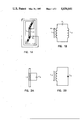
- FIG. 1A illustrates one preferred embodiment of the frequency divider of the present invention.
- FIG. 1B is an equivalent circuit of the frequency divider of FIG. 1A.
- FIG. 2A illustrates an alternative preferred embodiment of the frequency divider of the present invention.
- FIG. 2B is an equivalent circuit of the frequency divider of FIG. 2A.
- FIG. 3A shows a waveform H of the electromagnetic radiation at the first predetermined frequency detected by the nonlinear inductor at a first amplitude of said detected electromagnetic radiation and a waveform I of the current flowing in the frequency divider of FIG. 1A when said first amplitude of electromagnetic radiation at the first frequency is detected by the nonlinear inductor.
- FIG. 3B shows the frequency spectrum for the electromagnetic radiation transmitted by the frequency divider of FIG. 1A in response to detection of electromagnetic radiation of the first amplitude as shown in FIG. 3A.
- FIG. 4A shows a waveform H of the electromagnetic radiation at the first predetermined frequency detected by the nonlinear inductor at a second amplitude of said detected electromagnetic radiation greater than that shown in FIG. 3A and a waveform I of the current flowing in the frequency divider of FIG. 1A when said second amplitude of electromagnetic radiation at the first frequency is detected by the nonlinear inductor.
- FIG. 4B shows the frequency spectrum for the electromagnetic radiation transmitted by the frequency divider of FIG. 1A in response to detection of electromagnetic radiation of the second amplitude as shown in FIG. 4A.
- FIG. 5A shows a waveform H of the electromagnetic radiation at the first predetermined frequency detected by the nonlinear inductor at a third amplitude of said detected electromagnetic radiation greater than that shown in FIG. 4A and a waveform I of the current flowing in the frequency divider of FIG. 1A when said third amplitude of electromagnetic radiation at the first frequency is detected by the nonlinear conductor.
- FIG. 5B shows the frequency spectrum for the electromagnetic radiation transmitted by the frequency divider of FIG. 1A in response to detection of electromagnetic radiation of the third amplitude as shown in FIG. 5A.
- FIG. 6 is a frequency-division bifurcation diagram for the frequency divider of FIG. 1A as observed on an oscilloscope.
- FIG. 7 is a computer generated frequency-division bifurcation diagram based upon a mathematical model of the frequency divider of FIG. 1A.
- FIG. 8 is a block diagram of a presence detection system including a frequency divider according to the present invention.
- one preferred embodiment of the frequency divider of the present invention consists of a nonlinear inductor L1, a second inductor L2 and a capacitance C1, all connected in series with each other to define a series resonant circuit.
- the values of these components are chosen to define a series resonant circuit that detects electromagnetic radiation at a first predetermined frequency and responds to said detection by transmitting electromagnetic radiation at a second frequency that is a sub-harmonic of the first frequency.
- the nonlinear inductor L1 is constructed by closely winding the required number of turns of insulated wire around a core 10 that includes an elongated thin flat ribbon of low-coercivity amorphous magnetic material, such as an alloy sold by Allied-Signal Corporation of Morristown, N.J. that is identified as "METGLAS 2714A". METGLAS is a trademark of Allied-Signal Corporation.
- the ratio of the overall length of the ribbon 10 to the square root of the cross-sectional area of the ribbon should be at least one-hundred-fifty to one.
- the coil of the second inductor L2 is wound around the perimeter of the circuit as shown in FIG. 1A, and is positioned so as not to mutually couple the second inductor L2 to the nonlinear inductor L1.
- FIGS. 2A and 2B An alternative preferred embodiment of the frequency divider of the present invention is shown in FIGS. 2A and 2B.
- This embodiment consists of a nonlinear inductor L3 and a capacitance C4 connected in series with each other to define a series resonant circuit.
- the values of these components are chosen to define a series resonant circuit that detects electromagnetic radiation at a first predetermined frequency and responds to said detection by transmitting electromagnetic radiation at a second frequency that is a sub-harmonic of the first frequency.
- the nonlinear inductor L3 is constructed in the same manner as the nonlinear inductor L1 in the frequency divider shown in FIGS. 1A and 1B.
- the frequency divider of FIG. 2A is not as efficient as the frequency divider of FIG. 1A because of a smaller capture area; but it is simpler and less costly to manufacture.
- FIG. 3A shows the relative amplitude of a waveform H of the electromagnetic radiation at the first predetermined frequency detected by the nonlinear inductor and a waveform I of the current flowing in the resonant circuit of FIG. 1A.
- FIG. 3B is the corresponding frequency spectrum of the current in the resonant circuit of FIG. 1A.
- FIGS. 4A and 4B and 5A and 5B show the result of increasing the amplitude of the interrogating electromagnetic field.
- the circuit of FIG. 1A undergoes progressive stages of frequency division as a function of the amplitude of the detected electromagnetic radiation at the first predetermined frequency and eventually reaches the chaotic state shown in FIGS. 5A and 5B.
- the X i correspond to charge and current flowing in the circuit and ⁇ is the amplitude of the driving voltage.
- the theory predicts that the modulation parameter, ⁇ , should asymtotically satisfy the recurrence relation
- FIG. 6 is a typical real-time bifurcation diagram of the resonant circuit of FIG. 1A.
- This diagram is the result of sampling and displaying the instantaneous current, i(n*T), flowing in the series resonant circuit of FIG. 1A at the beginning of each cycle of the detected electromagnetic radiation at the first predetermined frequency on the Y-axis of an oscilloscope.
- the amplitude of the detected electromagnetic radiation at the first predetermined frequency is slowly varied and displayed along the X-axis.
- the diagram is useful because it clearly reveals threshold values of amplitude for progressive frequency-division bifurcations, convergence rate, rescaling factor, and the onset of chaotic behavior.
- Bifurcations at f/2, f/4, and f/8 are visible, as well as a window at f/5 in the chaotic region. This behavior may be exploited as a characteristic signature of the invention.
- the flux ⁇ B , thru the nonlinear inductor L1 is derived from the field generated by the current i(t), flowing thru the coil surrounding it and any external magnetic field, such as the earth's magnetic field.
- the external steady magnetic field is equivalent to adding a D.C. component to the current flowing in the circuit.
- ⁇ B is the saturation flux
- i c is the saturation current
- W is 2 ⁇ times the frequency of the detected electromagnetic radiation at the first predetermined frequency; E is the amplitude of said detected electromagnetic radiation; R is the wire resistance, and V c is the voltage across the capacitor C1.
- the bias level, i dc was set equal to i c for this diagram and the result is a very low threshold, with E being approximately equal to 0, for the first bifurcation. This condition is desirable when using the frequency divider of FIG. 1A as a transponder contained within an electronic tag in a presence detection system.
- the circuit of FIG. 1A shows the lowest threshold for bifurcation when the external magnetic bias field is equivalent to the field generated by the saturation current, i c , in the coil wrapped around the amorphous magnetic strip 10 of the nonlinear inductor L1; and the circuit is series resonant at one-half the frequency of the detected electromagnetic radiation at the first predetermined frequency.
- the biasing magnetic field may simply be the Earth's magnetic field, or a small permanent magnet placed near the nonlinear inductor.
- FIG. 8 Such system includes a transmitter 20, an electronic tag 22, a detection system 24 and a permanent magnet 26.
- the transmitter 20 transmits an electromagnetic radiation signal 28 of a first predetermined frequency into a surveillance zone 30.
- the tag 22 is attached to an article (not shown) to be detected within the surveillance zone 30.
- the tag 22 includes a batteryless, portable, frequency divider constructed as described above with reference to either FIG. 1A or FIG. 2A.
- the permanent magnet 26 provides an external magnetic bias field within the surveillance zone 30 that is equivalent in strength to the magnetic field generated by the saturation current in the coil wound around the core of the nonlinear inductor L1 in the frequency divider in response to the detected electromagnetic radiation at the first predetermined frequency.
- the detection system 24 detects electromagnetic radiation at the second frequency in the surveillance zone 30, and thereby detects the presence of the tag 22 in the surveillance zone 30.
- the frequency-division bifurcation characteristic of the resonant circuit of FIG. 1A is utilized by causing the transmitter 20 to transmit electromagnetic radiation at the first frequency having an amplitude that causes the resonant circuit to transmit electromagnetic radiation at multiple sub-harmonics of the first frequency.
- the detection system 24 then must detect electromagnetic radiation 32 in the surveillance zone 30 at each of the multiple sub-harmonics in order to detect the presence of a tag 22 in the surveillance zone 30.
- the present invention further provides a batteryless, portable, frequency divider that consists of an elongated thin flat ribbon of low coercivity magnetoelastic amorphous magnetic material that has been annealed in a magnetic field that is transverse to the length of the ribbon and in the the plane of the ribbon, and which detects electromagnetic radiation having a given frequency and responds to the detection of said radiation by transmitting electromagnetic radiation at a subharmonic of the given frequency of the detected radiation.
- Such frequency divider is included in a tag for use in a presence detection system according to the present invention.
- the frequency-divider ribbon has a characteristic electromagnetic resonant frequency "f", and responds to detection of electromagnetic radiation having a frequency nf, wherein "n" is an even integer, by transmitting electromagnetic radiation at a sub-harmonic of the frequency of the detected radiation.
- the characteristic electromagnetic resonant frequency of the frequency-divider ribbon is dependent upon the length of the ribbon.
- METGLAS is a trademark of Allied-Signal Corporation.
- the other amorphous magnetic materials described in Table IV in Anderson, III U.S. Pat. No. 4,553,136 et al. also may be processed to provide a ribbon that exhibits frequency-division characteristics. These materials are Fe 82 B 12 Si 6 and Fe 78 B 13 Si 9 .
- the amorphous magnetic material is processed to provide the frequency-divider ribbon by the following process.
- the cut ribbon is then annealed in the presence of a magnetic field that is transverse to the length of the ribbon and in the plane of the ribbon.
- a ribbon that has been so processed is referred to herein as a "frequency-divider ribbon.” This process creates a uniaxial magnetic anisotropy that is necessary for a large interaction between stress and strain and the orientation of the magnetic moment.
- the characteristic electromagnetic resonant frequency of the frequency-divider ribbon is independent of the the characteristic mechanical resonant frequency of the ribbon and appears to be relatively independent of the strength of any external magnetic bias field, except that frequency division does not occur unless an external magnetic bias field of at least a predetermined strength is applied to the frequency divider ribbon.
- METGLAS 2605SC material was cut into ribbons that were approximately 10 cm by 0.2 cm.
- the material had a thickness, as cast, in a range of about 25 to 38 microns.
- the resultant frequency-divider ribbon was observed to have a characteristic mechanical resonant frequency of approximately 10 KHz when an external magnetic bias field of 0.55 Oersteds was applied thereto.
- the characteristic mechanical resonant frequency of the ribbon was approximately 9.4 KHz.
- the characteristic electromagnetic resonant frequency of the frequency-divider ribbon remained relatively unchanged at approximately 2 KHz.
- the amplitude of the signal transmitted by the frequency-divider ribbon at the subharmonic frequency was dependent upon the strength of the applied external magnetic bias field.
- the highest amplitude of the subharmonic signal was observed when the strength of the applied external magnetic bias field was approximately the same as the strength of the transmitted signal detected by the frequency-divider ribbon and the frequency of the detected transmitted signal was approximately twice the characteristic mechanical resonant frequency of the frequency-divider ribbon.
- Frequency division was observed at even-numbered multiples of the characteristic electromagnetic resonant frequency of the frequency-divider ribbon.
- the frequency-divider ribbon responded to a 4 KHz signal by transmitting a 2 KHz signal; responded to an 8 KHz signal by transmitting a 4 KHz signal; responded to a 12 KHz signal by transmitting a 6 KHz signal; etc.
- Subharmonics at one-half the frequency of detected transmitted signals having frequencies other than nf also were observed, but at significantly lower amplitudes.
- the highest amplitude subharmonic signal observed was the 10 KHz signal transmitted by the frequency-divider ribbon in response to detection of a 20 KHz transmitted signal.
- the frequency-divider ribbon is included in the tag 22 in the presence detection system of FIG. 8, described above, in place of the frequency divider of FIG. 1A or FIG. 2A.
- the strength of the external magnetic bias field applied by the permanent magnet 26 is approximately the same as the strength of the electromagnetic radiation signal 28 transmitted into the surveillance zone by the transmitter 20.
- the frequency of the electromagnetic radiation signal 28 transmitted by the transmitter 20 is approximately twice the characteristic mechanical resonant frequency of the frequency-divider ribbon.
- the frequency-divider ribbon in the tag 22 detects the transmitted electromagnetic signal 28 and responds thereto by transmitting a signal 32 at a subharmonic of the frequency of the transmitted signal 28.
- the detection system 24 is tuned to detect a subharmonic, preferably one-half, of the frequency of the transmitted signal 28 to thereby detect the presence of the tag 22 in the surveillance zone 30.
- the strength of the Earth's magnetic field may be adequate to provide the external magnetic bias field in the surveillance zone 30, whereby the permanent magent 26 may be omitted.
- the tag includes a plurality of frequency-divider ribbons of different lengths, which thereby have different characteristic electromagnetic resonant frequencies. Different combinations of frequency-divider ribbons are included in different tags to thereby provide uniquely coded tags.
- the transmitter 20 provides a transmitted signal 28 that is swept over a predetermined range of frequencies that includes each of the frequencies that are twice the characteristic electromagnetic resonant frequency of each of the frequency-divider ribbons; and the detection system 24 detects signals at each of the characteristic electromagnetic resonant frequencies to detect the presence of the tag 22 in the surveillance zone 30.
- the detection system 24 detects an acoustic wave at the characteristic mechanical resonant frequency of the frequency-divider ribbon to detect the presence of the tag 22 in the surveillance zone 30.
Abstract
Description
dx;/dt=F.sub.i (X.sub.1,X.sub.2, . . . ,X.sub.n,λ), i=1,2, . . . n,(Eq. 1)
(λ.sub.n+1 -λ.sub.n)/(λ.sub.n+2 -λ.sub.n+1)=δ (Eq. 2)
i.sub.eq (t)=i(t)+i.sub.dc (Eq. 4)
if-i.sub.c <i.sub.eq <i.sub.c
then Φ.sub.B =M.sub.1 i.sub.eq (Eq. 5)
if i.sub.eq >i.sub.c
then Φ.sub.B =M.sub.o i.sub.eq +(I.sub.Bs -M.sub.o i.sub.c)(Eq. 6)
if i.sub.eq <-i.sub.c
then Φ.sub.B =M.sub.o i.sub.eq -(I.sub.Bs -M.sub.o i.sub.c)(Eq. 7I)
i+i.sub.dc for i.sub.eq.
if -i.sub.c <(i+i.sub.dc)<i.sub.c
then dΦ.sub.B /dt=M.sub.1 di/dt (Eq. 8)
if (i+i.sub.dc)>i.sub.c
then dΦ.sub.B /dt=M.sub.o di/dt (Eq. 9)
if (i+i.sub.dc)<-i.sub.c
then dΦ.sub.B /dt=M.sub.o di/dt (Eq. 10)
EsinWt=L.sub.2 di/dt+Ri+M(i)di/dt+V.sub.c (Eq. 11)
i=CdV.sub.c /dt (Eq. 12)
f.sub.m =c.sup.H /2L (Eq. 13)
Claims (38)
Priority Applications (8)
| Application Number | Priority Date | Filing Date | Title |
|---|---|---|---|
| US06/775,568 US4654641A (en) | 1985-09-13 | 1985-09-13 | Frequency divider with single resonant circuit and use thereof as a transponder in a presence detection system |
| US06/888,877 US4727360A (en) | 1985-09-13 | 1986-07-31 | Frequency-dividing transponder and use thereof in a presence detection system |
| AT86307056T ATE73247T1 (en) | 1985-09-13 | 1986-09-12 | FREQUENCY-DIVIVING TRANSPONDER AND ITS APPLICATION IN AN PRESENCE DETECTION SYSTEM. |
| JP61215607A JP2561249B2 (en) | 1985-09-13 | 1986-09-12 | transponder |
| EP86307056A EP0216584B1 (en) | 1985-09-13 | 1986-09-12 | Frequency-dividing transponder and use thereof in a presence detection system |
| NO863641A NO173678C (en) | 1985-09-13 | 1986-09-12 | Portable, battery-free transponder for detection of electromagnetic radiation |
| ES8601878A ES2002150A6 (en) | 1985-09-13 | 1986-09-12 | Frequency-dividing transponder and use thereof in a presence detection system. |
| DE8686307056T DE3684072D1 (en) | 1985-09-13 | 1986-09-12 | FREQUENCY-DIVIDING TRANSPONDER AND ITS APPLICATION IN AN ATTENDANCE DETECTION SYSTEM. |
Applications Claiming Priority (1)
| Application Number | Priority Date | Filing Date | Title |
|---|---|---|---|
| US06/775,568 US4654641A (en) | 1985-09-13 | 1985-09-13 | Frequency divider with single resonant circuit and use thereof as a transponder in a presence detection system |
Related Child Applications (1)
| Application Number | Title | Priority Date | Filing Date |
|---|---|---|---|
| US06/888,877 Continuation-In-Part US4727360A (en) | 1985-09-13 | 1986-07-31 | Frequency-dividing transponder and use thereof in a presence detection system |
Publications (1)
| Publication Number | Publication Date |
|---|---|
| US4654641A true US4654641A (en) | 1987-03-31 |
Family
ID=25104804
Family Applications (1)
| Application Number | Title | Priority Date | Filing Date |
|---|---|---|---|
| US06/775,568 Expired - Lifetime US4654641A (en) | 1985-09-13 | 1985-09-13 | Frequency divider with single resonant circuit and use thereof as a transponder in a presence detection system |
Country Status (1)
| Country | Link |
|---|---|
| US (1) | US4654641A (en) |
Cited By (17)
| Publication number | Priority date | Publication date | Assignee | Title |
|---|---|---|---|---|
| US4866424A (en) * | 1988-01-11 | 1989-09-12 | Eg&G Astrophysics Research Corporation | Metal detector coil |
| US4940966A (en) * | 1987-06-08 | 1990-07-10 | Scientific Generics Limited | Article detection and/or recognition using magnetic devices |
| US4992794A (en) * | 1988-10-10 | 1991-02-12 | Texas Instruments Incorporated | Transponder and method for the production thereof |
| US5001458A (en) * | 1986-08-14 | 1991-03-19 | Tyren Carl | Method of remote sensing of objects |
| AU620085B2 (en) * | 1988-04-18 | 1992-02-13 | Security Tag Systems, Inc. | Frequency-dividing amorphous wire transponder for use in presence detection system |
| US5382780A (en) * | 1993-10-01 | 1995-01-17 | Duncan Industries Parking Control Systems Corp. | Portable time metering device |
| US5406262A (en) * | 1993-06-16 | 1995-04-11 | Security Tag Systems, Inc. | Adjusting magnetic bias field intensity in EAS presence detection system to enhance detection |
| US5574665A (en) * | 1994-04-29 | 1996-11-12 | International Business Machines Corporation | Receiver apparatus and method for frequency tagging |
| WO2000017835A1 (en) * | 1998-09-24 | 2000-03-30 | Tuotesuoja Sirpa Järvensivu Oy | Article surveillance tag |
| US20080018478A1 (en) * | 2004-04-12 | 2008-01-24 | David Russell | Detection-resistant transponder with "stealth packaging" for high-risk surveillance applications |
| US20090159701A1 (en) * | 2007-12-24 | 2009-06-25 | Dynamics Inc. | Payment cards and devices with enhanced magnetic emulators |
| US20090166434A1 (en) * | 2007-12-26 | 2009-07-02 | Murata Manufacturing Co., Ltd. | Antenna device and radio frequency ic device |
| US20100052865A1 (en) * | 2005-01-18 | 2010-03-04 | Checkpoint Systems, Inc. | Multiple frequency detection system |
| WO2018237281A1 (en) * | 2017-06-22 | 2018-12-27 | Checkpoint Systems, Inc. | Detectable folded coil |
| US11023795B2 (en) * | 2016-04-13 | 2021-06-01 | Universidad Complutense De Madrid | Tag system and method for long-distance detection of objects |
| US11316560B1 (en) | 2020-10-23 | 2022-04-26 | Nxp B.V. | Magnetic induction device |
| US11544518B2 (en) | 2017-06-22 | 2023-01-03 | Checkpoint Systems, Inc. | Deactivatable metal tag |
Citations (10)
| Publication number | Priority date | Publication date | Assignee | Title |
|---|---|---|---|---|
| GB2017454A (en) * | 1978-01-11 | 1979-10-03 | Tag Radionics Ltd | Presence sensing system |
| US4298862A (en) * | 1979-04-23 | 1981-11-03 | Allied Chemical Corporation | Amorphous antipilferage marker |
| US4314373A (en) * | 1976-05-24 | 1982-02-02 | Harris Corporation | Passive transmitter including parametric device |
| US4481428A (en) * | 1981-05-19 | 1984-11-06 | Security Tag Systems, Inc. | Batteryless, portable, frequency divider useful as a transponder of electromagnetic radiation |
| US4484184A (en) * | 1979-04-23 | 1984-11-20 | Allied Corporation | Amorphous antipilferage marker |
| US4495487A (en) * | 1981-11-02 | 1985-01-22 | Allied Corporation | Amorphous antipilferage marker |
| US4510489A (en) * | 1982-04-29 | 1985-04-09 | Allied Corporation | Surveillance system having magnetomechanical marker |
| US4510490A (en) * | 1982-04-29 | 1985-04-09 | Allied Corporation | Coded surveillance system having magnetomechanical marker |
| US4553136A (en) * | 1983-02-04 | 1985-11-12 | Allied Corporation | Amorphous antipilferage marker |
| US4572976A (en) * | 1982-12-10 | 1986-02-25 | N.V. Nederlandsche Apparatenfabriek Nedap | Transponder for electromagnetic detection system with non-linear circuit |
-
1985
- 1985-09-13 US US06/775,568 patent/US4654641A/en not_active Expired - Lifetime
Patent Citations (10)
| Publication number | Priority date | Publication date | Assignee | Title |
|---|---|---|---|---|
| US4314373A (en) * | 1976-05-24 | 1982-02-02 | Harris Corporation | Passive transmitter including parametric device |
| GB2017454A (en) * | 1978-01-11 | 1979-10-03 | Tag Radionics Ltd | Presence sensing system |
| US4298862A (en) * | 1979-04-23 | 1981-11-03 | Allied Chemical Corporation | Amorphous antipilferage marker |
| US4484184A (en) * | 1979-04-23 | 1984-11-20 | Allied Corporation | Amorphous antipilferage marker |
| US4481428A (en) * | 1981-05-19 | 1984-11-06 | Security Tag Systems, Inc. | Batteryless, portable, frequency divider useful as a transponder of electromagnetic radiation |
| US4495487A (en) * | 1981-11-02 | 1985-01-22 | Allied Corporation | Amorphous antipilferage marker |
| US4510489A (en) * | 1982-04-29 | 1985-04-09 | Allied Corporation | Surveillance system having magnetomechanical marker |
| US4510490A (en) * | 1982-04-29 | 1985-04-09 | Allied Corporation | Coded surveillance system having magnetomechanical marker |
| US4572976A (en) * | 1982-12-10 | 1986-02-25 | N.V. Nederlandsche Apparatenfabriek Nedap | Transponder for electromagnetic detection system with non-linear circuit |
| US4553136A (en) * | 1983-02-04 | 1985-11-12 | Allied Corporation | Amorphous antipilferage marker |
Non-Patent Citations (7)
| Title |
|---|
| M. J. Feigenbaum, J. Stat. Phys. 19, p. 25, 1978; * |
| Mitchell et al., "Magnetoelastic Effects in Fe71 Co9 B20 Glassy Ribbons" J. Appl. Phys. 50 (3), Mar. 1979, p. 1627; |
| Mitchell et al., Magnetoelastic Effects in Fe 71 Co 9 B 20 Glassy Ribbons J. Appl. Phys. 50 (3), Mar. 1979, p. 1627; * |
| Modzelewski et al., "Magnetomechanical Coupling and Permeability in Transversely Annealed Metglas 2605 Alloys", IEEE Transactions on Magnetics, vol. MAG-17, No. 6, Nov. 1981, p. 2837; |
| Modzelewski et al., Magnetomechanical Coupling and Permeability in Transversely Annealed Metglas 2605 Alloys , IEEE Transactions on Magnetics, vol. MAG 17, No. 6, Nov. 1981, p. 2837; * |
| P. S. Linsay, Physical Review Letters, vol. 47, No. 19, pp. 1349 1352, Nov. 1981; * |
| P. S. Linsay, Physical Review Letters, vol. 47, No. 19, pp. 1349-1352, Nov. 1981; |
Cited By (23)
| Publication number | Priority date | Publication date | Assignee | Title |
|---|---|---|---|---|
| US5001458A (en) * | 1986-08-14 | 1991-03-19 | Tyren Carl | Method of remote sensing of objects |
| US4940966A (en) * | 1987-06-08 | 1990-07-10 | Scientific Generics Limited | Article detection and/or recognition using magnetic devices |
| US4866424A (en) * | 1988-01-11 | 1989-09-12 | Eg&G Astrophysics Research Corporation | Metal detector coil |
| AU620085B2 (en) * | 1988-04-18 | 1992-02-13 | Security Tag Systems, Inc. | Frequency-dividing amorphous wire transponder for use in presence detection system |
| US4992794A (en) * | 1988-10-10 | 1991-02-12 | Texas Instruments Incorporated | Transponder and method for the production thereof |
| US5406262A (en) * | 1993-06-16 | 1995-04-11 | Security Tag Systems, Inc. | Adjusting magnetic bias field intensity in EAS presence detection system to enhance detection |
| US5382780A (en) * | 1993-10-01 | 1995-01-17 | Duncan Industries Parking Control Systems Corp. | Portable time metering device |
| US5574665A (en) * | 1994-04-29 | 1996-11-12 | International Business Machines Corporation | Receiver apparatus and method for frequency tagging |
| WO2000017835A1 (en) * | 1998-09-24 | 2000-03-30 | Tuotesuoja Sirpa Järvensivu Oy | Article surveillance tag |
| US7339464B2 (en) * | 2004-04-12 | 2008-03-04 | David Russell | Detection-resistant transponder with “stealth packaging” for high-risk surveillance applications |
| US20080018478A1 (en) * | 2004-04-12 | 2008-01-24 | David Russell | Detection-resistant transponder with "stealth packaging" for high-risk surveillance applications |
| US20100052865A1 (en) * | 2005-01-18 | 2010-03-04 | Checkpoint Systems, Inc. | Multiple frequency detection system |
| US20090159701A1 (en) * | 2007-12-24 | 2009-06-25 | Dynamics Inc. | Payment cards and devices with enhanced magnetic emulators |
| US8915448B2 (en) * | 2007-12-26 | 2014-12-23 | Murata Manufacturing Co., Ltd. | Antenna device and radio frequency IC device |
| US8070070B2 (en) * | 2007-12-26 | 2011-12-06 | Murata Manufacturing Co., Ltd. | Antenna device and radio frequency IC device |
| US20120235871A1 (en) * | 2007-12-26 | 2012-09-20 | Murata Manufacturing Co., Ltd. | Antenna device and radio frequency ic device |
| US20090166434A1 (en) * | 2007-12-26 | 2009-07-02 | Murata Manufacturing Co., Ltd. | Antenna device and radio frequency ic device |
| US11023795B2 (en) * | 2016-04-13 | 2021-06-01 | Universidad Complutense De Madrid | Tag system and method for long-distance detection of objects |
| WO2018237281A1 (en) * | 2017-06-22 | 2018-12-27 | Checkpoint Systems, Inc. | Detectable folded coil |
| US11276286B2 (en) | 2017-06-22 | 2022-03-15 | Checkpoint Systems, Inc. | Detectable folded coil |
| US11544518B2 (en) | 2017-06-22 | 2023-01-03 | Checkpoint Systems, Inc. | Deactivatable metal tag |
| US11316560B1 (en) | 2020-10-23 | 2022-04-26 | Nxp B.V. | Magnetic induction device |
| EP3989450A1 (en) * | 2020-10-23 | 2022-04-27 | Nxp B.V. | Magnetic induction device |
Similar Documents
| Publication | Publication Date | Title |
|---|---|---|
| EP0216584B1 (en) | Frequency-dividing transponder and use thereof in a presence detection system | |
| US4654641A (en) | Frequency divider with single resonant circuit and use thereof as a transponder in a presence detection system | |
| US4622543A (en) | Surveillance system having acoustic magnetomechanical marker | |
| US4510489A (en) | Surveillance system having magnetomechanical marker | |
| US4510490A (en) | Coded surveillance system having magnetomechanical marker | |
| EP0096182B1 (en) | Coded surveillance system having magnetomechanical marker | |
| US4215342A (en) | Merchandise tagging technique | |
| US3747086A (en) | Deactivatable ferromagnetic marker for detection of objects having marker secured thereto and method and system of using same | |
| US5565847A (en) | Magnetic tag using acoustic or magnetic interrogation | |
| US5729201A (en) | Identification tags using amorphous wire | |
| US3983552A (en) | Pilferage detection systems | |
| EP0516244B1 (en) | Improved label for use in antitheft surveillance system | |
| US4660025A (en) | Article surveillance magnetic marker having an hysteresis loop with large Barkhausen discontinuities | |
| US7205893B2 (en) | Marker for mechanically resonant article surveillance system | |
| EP0121649A1 (en) | Amorphous antipilferage marker | |
| US3754226A (en) | Conductive-ring ferromagnetic marker and method and system for using same | |
| AU1156692A (en) | Remotely readable data storage devices and apparatus | |
| CA1294017C (en) | Deactivatable coded marker and magnetic article surveillance system | |
| US4622542A (en) | Magnetic article surveillance system, method and coded marker | |
| US5539380A (en) | Metallic glass alloys for mechanically resonant marker surveillance systems | |
| US5414412A (en) | Frequency dividing transponder, including amorphous magnetic alloy and tripole strip of magnetic material | |
| US4823113A (en) | Glassy alloy identification marker | |
| O’Handley | Magnetic materials for EAS sensors | |
| US4864281A (en) | Ferromagnetic label for use in anti-theft surveillance system | |
| KR100478114B1 (en) | Metallic glass alloys for mechanically resonant marker surveillance systems |
Legal Events
| Date | Code | Title | Description |
|---|---|---|---|
| AS | Assignment |
Owner name: SECURITY TAG SYSTEMS, INC., 1615 118TH AVENUE NORT Free format text: ASSIGNMENT OF ASSIGNORS INTEREST.;ASSIGNORS:FERGUSON, LUCIAN G.;CHARLOT, LINCOLN H. JR.;REEL/FRAME:004487/0010 Effective date: 19851021 |
|
| STCF | Information on status: patent grant |
Free format text: PATENTED CASE |
|
| FPAY | Fee payment |
Year of fee payment: 4 |
|
| FEPP | Fee payment procedure |
Free format text: PAT HLDR NO LONGER CLAIMS SMALL ENT STAT AS INDIV INVENTOR (ORIGINAL EVENT CODE: LSM1); ENTITY STATUS OF PATENT OWNER: LARGE ENTITY |
|
| FPAY | Fee payment |
Year of fee payment: 8 |
|
| FPAY | Fee payment |
Year of fee payment: 12 |
|
| AS | Assignment |
Owner name: SENSORMATIC ELECTRONICS CORPORATION, FLORIDA Free format text: MERGER/CHANGE OF NAME;ASSIGNOR:SENSORMATIC ELECTRONICS CORPORATION;REEL/FRAME:012991/0641 Effective date: 20011113 Owner name: SENSORMATIC ELECTRONICS CORPORATION, FLORIDA Free format text: MERGER;ASSIGNOR:SECURITY TAG SYSTEMS, INC.;REEL/FRAME:013000/0536 Effective date: 19950629 |