US4648699A - Point contact development of imaging sheets employing photosensitive microcapsules - Google Patents
Point contact development of imaging sheets employing photosensitive microcapsules Download PDFInfo
- Publication number
- US4648699A US4648699A US06/793,374 US79337485A US4648699A US 4648699 A US4648699 A US 4648699A US 79337485 A US79337485 A US 79337485A US 4648699 A US4648699 A US 4648699A
- Authority
- US
- United States
- Prior art keywords
- point contact
- imaging
- rupturing
- microcapsules
- imaging material
- Prior art date
- Legal status (The legal status is an assumption and is not a legal conclusion. Google has not performed a legal analysis and makes no representation as to the accuracy of the status listed.)
- Expired - Lifetime
Links
Images


Classifications
-
- G—PHYSICS
- G03—PHOTOGRAPHY; CINEMATOGRAPHY; ANALOGOUS TECHNIQUES USING WAVES OTHER THAN OPTICAL WAVES; ELECTROGRAPHY; HOLOGRAPHY
- G03F—PHOTOMECHANICAL PRODUCTION OF TEXTURED OR PATTERNED SURFACES, e.g. FOR PRINTING, FOR PROCESSING OF SEMICONDUCTOR DEVICES; MATERIALS THEREFOR; ORIGINALS THEREFOR; APPARATUS SPECIALLY ADAPTED THEREFOR
- G03F7/00—Photomechanical, e.g. photolithographic, production of textured or patterned surfaces, e.g. printing surfaces; Materials therefor, e.g. comprising photoresists; Apparatus specially adapted therefor
- G03F7/002—Photomechanical, e.g. photolithographic, production of textured or patterned surfaces, e.g. printing surfaces; Materials therefor, e.g. comprising photoresists; Apparatus specially adapted therefor using materials containing microcapsules; Preparing or processing such materials, e.g. by pressure; Devices or apparatus specially designed therefor
- G03F7/0022—Devices or apparatus
- G03F7/0027—Devices or apparatus characterised by pressure means
-
- G—PHYSICS
- G03—PHOTOGRAPHY; CINEMATOGRAPHY; ANALOGOUS TECHNIQUES USING WAVES OTHER THAN OPTICAL WAVES; ELECTROGRAPHY; HOLOGRAPHY
- G03B—APPARATUS OR ARRANGEMENTS FOR TAKING PHOTOGRAPHS OR FOR PROJECTING OR VIEWING THEM; APPARATUS OR ARRANGEMENTS EMPLOYING ANALOGOUS TECHNIQUES USING WAVES OTHER THAN OPTICAL WAVES; ACCESSORIES THEREFOR
- G03B2227/00—Photographic printing apparatus
- G03B2227/32—Projection printing apparatus, e.g. enlarging apparatus, copying camera
- G03B2227/325—Microcapsule copiers
-
- Y—GENERAL TAGGING OF NEW TECHNOLOGICAL DEVELOPMENTS; GENERAL TAGGING OF CROSS-SECTIONAL TECHNOLOGIES SPANNING OVER SEVERAL SECTIONS OF THE IPC; TECHNICAL SUBJECTS COVERED BY FORMER USPC CROSS-REFERENCE ART COLLECTIONS [XRACs] AND DIGESTS
- Y10—TECHNICAL SUBJECTS COVERED BY FORMER USPC
- Y10T—TECHNICAL SUBJECTS COVERED BY FORMER US CLASSIFICATION
- Y10T428/00—Stock material or miscellaneous articles
- Y10T428/29—Coated or structually defined flake, particle, cell, strand, strand portion, rod, filament, macroscopic fiber or mass thereof
- Y10T428/2982—Particulate matter [e.g., sphere, flake, etc.]
- Y10T428/2984—Microcapsule with fluid core [includes liposome]
- Y10T428/2985—Solid-walled microcapsule from synthetic polymer
- Y10T428/2987—Addition polymer from unsaturated monomers only
Definitions
- the present invention relates generally to an imaging system utilizing imaging sheets having a surface coating of rupturable photosensitive microcapsules and, more particularly, to a method and apparatus for processing such imaging sheets by means of one or more point contacts.
- U.S. Pat. Nos. 4,440,846 and 4,399,209 which are assigned to The Mead Corporation and hereby incorporated by reference, describe an imaging system wherein a photosensitive layer comprising microcapsules containing a photosensitive composition in the internal phase is image-wise exposed to actinic radiation and subjected to a uniform rupturing force whereupon the microcapsules rupture and image-wise release the internal phase.
- the imaging system is particularly advantageous because it is a totally dry system and does not rely upon the application of wet development processing solutions to produce the image.
- An imageforming chromogenic material such as a substantially colorless color former, is typically associated with the microcapsules.
- the color former image-wise reacts with a developer material and produces a color image.
- the microcapsules are typically ruptured by passing image-wise exposed imaging sheets through the nip between a pair of calender rollers.
- the diameter of the rollers must also be increased to maintain sufficient stiffness such that pressure applied to the ends of the rollers is distributed evenly along the entire expanse of the rollers.
- the diameter of the rollers must be doubled in order to maintain sufficient stiffness.
- a second arrangement for generating shear forces for processing imaging sheets is disclosed in commonly assigned U.S. patent application Ser. No. 670,447, which was filed on Nov. 13, 1984, now U.S. Pat. No. 4,578,340, and entitled “Free Particle Abrasion Development of Imaging Sheets Employing Photosensitive Microcapsules,” wherein imaging sheets are contacted with a bed of free particles such that the free particles pass over the microcapsules on the surface of the imaging sheets to rupture the microcapsules.
- a third arrangement is disclosed in U.S. patent application Ser. No. 711,779, filed Mar. 14, 1985, now U.S. Pat. No. 4,592,986, and entitled “Magnetic Brush Abrasion Development of Imaging Sheets Employing Photosensitive Microcapsules," wherein imaging sheets are processed by contacting the imaging sheets with a traveling pile formed by magnetically attractable free particles on a magnetic brush.
- the fibrous outer surface of the developer roll of U.S. Pat. No. 4,448,516 has limited microcapsule engaging surface area. Accordingly, as imaging sheets are processed by the developer roll to rupture the microcapsules on the sheets, oil released from the ruptured microcapsules accumulates on the limited surface area of the developer roll. After a given amount of oil accumulation, background coloring (fog) begins to increase on processed imaging sheets. Since background coloring detracts from the developed image, the developer rolls must be frequently changed to maintain high quality images. In the free particle and magnetic brush arrangements for processing imaging sheets, a similar build up of oil requires periodic, though less frequent, servicing to clean or replace the particle beds.
- New alternatives which offer more compact and less expensive techniques for developing imaging sheets, overcome deficiencies of the prior art and may be preferred for selected applications are in demand and serve to advance the art of imaging systems utilizing the imaging sheets of the referenced patents.
- microcapsule refers to both microcapsules having a discrete microcapsule wall and microcapsules formed in a so-called open phase system wherein the internal phase constituents are simply dispersed in a binder.
- photosensitive composition means a composition which changes viscosity in response to actinic radiation.
- chromogenic material refers to the color forming reactant which is encapsulated or otherwise associated with the microcapsules.
- developer refers to the reactant not associated with the microcapsules.
- an imaging sheet is processed by relatively moving the imaging sheet and at least one point contact which is resiliently biased into engagement with the imaging sheet such that the force of the point contact is applied to the imaging area of the imaging sheet.
- the present invention relates to a method and apparatus for rupturing the microcapsules which form a photosensitive layer on the aforementioned imaging sheets by supporting an imaging sheet to be processed, positioning at least one point contact in resilient pressure engagement with the imaging sheet, and relatively moving the imaging sheet and the at least one point contact to apply a uniform rupturing force to the imaging sheet thereby rupturing the microcapsules.
- a latent image in the imaging sheet is developed if the microcapsules are ruptured in the presence of a developer.
- a developer can be provided as a coating on the imaging sheet itself such that, as the microcapsules are ruptured, the developer and a chromogenic material, such as a colorless color former, interact and form the image.
- the developer may be provided on a receiver sheet which is aligned and in facing engagement with the imaging sheet such that, as the microcapsules rupture and release their internal phase, the chromogenic material interacts with the developer to form the image on the receiver sheet.
- a cylinder is mounted for rotation and an imaging sheet to be processed is secured to the cylinder. At least one point contact is positioned in resilient pressure engagement with the imaging sheet, and the cylinder is rotated while the at least one point contact is axially moved along the cylinder in synchronism with the rotation of the cylinder.
- an imaging sheet to be processed is secured to a substantially planar mounting platform.
- At least one point contact is positioned in resilient pressure engagement with the imaging sheet, and the point contact is moved over the portion of the mounting platform corresponding to the imaging sheet.
- the point contact comprises a ball mounted for rotation in an appropriate receiving socket such that the point contact is made by the ball as it rotates within the socket and over the imaging sheet.
- a web of imaging material may also be processed in accordance with yet another embodiment of the present invention by scrolling the web of imaging material past a processing station. At least one point contact is positioned adjacent to and in resilient engagement with the web at the processing station. The point contact is traversed over the web concurrently with the scrolling of the web to apply a uniform rupturing force to the web and thereby rupture the microcapsules as the web is scrolled past the processing station. The point contact may be traversed across the web, for example, by continuously sweeping the point contact around a substantially circular path.
- a primary object of the present invention to provide a method and apparatus for processing an imaging sheet by means of one or more point contacts through relative movement between the imaging sheet and the one or more point contacts in resilient pressure engagement with the imaging sheet such that the pressure of the one or more point contacts is applied to the imaging sheet to provide an effective uniform force to rupture the microcapsules and permit chromogenic material associated with the microcapsules to interact with a developer and thereby develop a latent image in the imaging sheet.
- FIGS. 1A and 1B show a self-contained imaging sheet and formation of a latent image in the imaging sheet which is then processed in accordance with the present invention to form an image as shown in FIG. 1C.
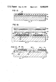
- FIGS. 2A and 2B show a transfer imaging sheet and the formation of a latent image in the imaging sheet which is then processed in accordance with the present invention to form an image as shown in FIG. 2C.
- FIGS. 3-6 are schematic views of illustrative embodiments of apparatus for processing imaging sheets in accordance with the present invention.
- FIGS. 7-10 are illustrative embodiments of point contacts which can be used in the present invention.
- FIGS. 1A and 2A illustrate embodiments of the imaging sheets in accordance with referenced U.S. Pat. Nos. 4,440,846 and 4,399,209, respectively.
- an imaging sheet 10 is constituted by a substrate 12 coated with a layer of microcapsules 14.
- the microcapsules 14 are filled with an internal phase 16 containing a photosensitive composition.
- the microcapsules 14 also contain chromogenic material; however, chromogenic material can be associated with the microcapsules 14 in other ways, such as by incorporation into the microcapsule wall or in a layer contiguous with the microcapsules.
- microcapsules 14 are not visible to the unaided eye, since the mean size of the microcapsules generally ranges from approximately 1-25 microns.
- a layer of developer material 20 is interposed between the layer of microcapsules 14 and the substrate 12.
- FIGS. 1B and 2B Exposure of the imaging sheets 10 by transmission imaging is shown in FIGS. 1B and 2B wherein a source of radiant energy 22 is positioned above the surface of the imaging sheets 10 with a mask 24 positioned therebetween.
- the substrate 12 is opaque and the photosensitive material within the microcapsules 14 is a positive working radiation curable material, i.e., the viscosity of the material increases upon exposure to actinic radiation.
- the radiation of the exposed areas 26 causes the radiation curable composition in the internal phase 16 of the microcapsules 14 to polymerize thereby gelling, solidifying or otherwise immobilizing the chromogenic material and preventing the chromogenic material from reacting with the developer material 20.
- internal phase 16' in the exposed areas 26 is shown as a solid; whereas, the internal phase 16 remains liquid in the unexposed areas 28.
- the imaging sheets 10 are processed in accordance with the present invention by subjecting the imaging sheets to a uniform rupturing force by means of one or more point contacts in resilient pressure engagement with the imaging sheets.
- the imaging sheets and the one or more point contacts are moved relative to one another such that the point contacts apply a uniform force to substantially the entire imaging sheets to rupture the microcapsules 14 such that the chromogenic material contained within the microcapsules 14 or otherwise associated therewith can interact with the developer material 20.
- the uniform rupturing force is applied by the one or more point contacts to substantially the entire imaging sheets by moving the point contacts, the imaging sheets or both the point contacts and the imaging sheets.
- the developer is on the same surface of the sheet 10 as the microcapsules 14, and upon rupturing the microcapsules 14, the internal phase migrates to the developer material 20 where it reacts with the developer material to form a visible image 30.
- the transfer imaging sheets as shown in FIGS. 2A, 2B and 2C, the developer 20 is formed as a layer of developer material on a separate substrate or receiver sheet 32. As shown in FIG. 2C, the receiver sheet 32 is aligned and in facing engagement with the transfer imaging sheet 10.
- the microcapsules 14 are ruptured and the internal phase migrates to the developer layer 20 of the receiver sheet 32 where it reacts with the developer material to form the image 30.
- FIG. 3 is a schematic perspective view of a first illustrative embodiment of apparatus for processing imaging sheets in accordance with the present invention.
- support means for receiving a sheet of imaging material comprises a cylinder 36 mounted for rotation and point contact means comprises a rotating ball device 38 as best shown in FIG. 7.
- the rotating ball device 38 comprises a ball 40 mounted for rotation in an appropriate receiving socket 42 which is in turn slidingly received within a sleeve 44 such that the ball 40 in the receiving socket 42 may be resiliently biased into an imaging sheet 10, for example, by means of a spring 46.
- the sleeve 44 may be threadingly engaged with a support block 48 to permit servicing of the rotating ball point contact device 38. It will be apparent to those skilled in the art that a large variety of arrangements are possible for mounting a rotating ball to form the point contact device 38 for use in the invention of the present application.
- motive means comprising an appropriate drive arrangement 50 produces relative movement between the cylinder 36 and the ball and socket point contact device 38.
- the drive arrangement 50 rotates the cylinder 36 in a counter-clockwise direction as shown in FIG. 3 by the arrow 52, and moves the ball and socket point contact device 38 axially along the cylinder 36, for example, by rotation of a screw thread 54, upon which the ball and socket point contact device 38 is supported.
- the drive arrangement 50 synchronizes the axial movement of the ball and socket point contact device 38 with the rotation of the cylinder 36 such that the point rupturing force exerted by the ball and socket point contact device 38 is scrolled along the cylinder 36 to contact substantially the entire sheet of imaging material received and supported upon the cylinder 36.
- a transfer imaging sheet 10 together with an associated receiver sheet 32 have been mounted upon the cylinder 36 by sheet securing means comprising clips 56, or preferably, by means of vacuum systems well known in the art.
- the imaging sheet 10 has been processed by rotating the cylinder 36 in the counter-clockwise direction indicated by the arrow 52 and moving the ball and socket point contact device 38 to the left to apply a uniform rupturing force over a band of the imaging sheet 10 extending from a point 58 near one end of the imaging sheet 10 to a point 60 approximately one-tenth of the distance along the imaging sheet 10.
- This development is revealed by a turned back corner of the imaging sheet 10 and indicated by a band 62 of an image formed on the receiver sheet 32 as if the imaging sheet 10 had not been exposed, and hence, represents a completely darkened image.
- processing time for developing an imaging sheet in accordance with the embodiment of FIG. 3 of the present invention may be reduced by the provision of multiple point contact devices.
- two additional point contact devices 38 have been indicated in dotted lines and would trace out bands 64 and 66 during the same period of time that the band 62 is traced out by the solid line point contact device 38 shown in FIG. 3.
- any reasonable number of point contact devices 38 may be provided to speed up the processing of an imaging sheet 10.
- the apparatus of FIG. 3 can be appropriately sized to accommodate a variety of imaging sheet sizes up to and including even the largest contemplated widths.
- the small area of the point contact device permits relatively low loading on the device which, due to the small area, is translated into adequately high pressures to rupture the microcapsules 14 and develop the imaging sheets 10.
- the resilient biasing of the one or more point contact devices into the surface of the support means for an imaging sheet accommodates any surface irregularities and greatly enhances image uniformity.
- the synchronization of the axial movement of the point contact device or devices 38 with the rotation of the cylinder 36 may be such as to just trace out the entire imaging sheet 10.
- an overlap of the paths of each point contact device may be provided such that the load or pressure exerted by each point contact device may be further reduced. Such overlap may also enhance the continuity of the image density resulting from the processing of the imaging sheet 10.
- FIG. 4 is a schematic perspective view of a second illustrative embodiment of apparatus for processing imaging sheets in accordance with the present invention.
- support means comprises a substantially planar mounting platform 70 and the motive means for moving at least one point contact device 38 over the portion of the mounting platform 70 corresponding to substantially the entire surface of a sheet 10 of imaging material comprises an X-Y transport device schematically illustrated by a screw thread 72 and associated support apparatus 74 which is well known in the art of X-Y plotters and will not be described in detail herein.
- a uniform rupturing force may be applied by the point contact device 38 to the imaging sheet 10 by means of traversing movements of the point contact device 38 as suggested by the arrows 76 in FIG. 4, or by other appropriate patterns such that the entire imaging sheet is traversed by the point contact device. It should be apparent in view of available X-Y plotters that the embodiment of FIG. 4 can be used to accommodate a large variety of imagining sheet sizes including the largest imaging sheets which may be required.
- FIG. 5 is a schematic view of another illustrative embodiment of apparatus for processing imaging sheets in accordance with the present invention, and in particular, for processing a continuous web of imaging material.
- a continuous web 78 of imaging material is shown as extending from a source roll 80.
- the web 78 is drawn or scrolled through an exposure station 82 where a latent image is impressed upon the web of imaging material, for example, as illustrated in FIGS. 1B and 2B.
- the web 78 is scrolled past a processing station 84.
- the processing station 84 includes a web support platform 86 which has a generally planar upper surface 88 having a width at least slightly exceeding the widest web of material to be processed.
- Point contact means comprising a ball and socket point contact device 90 in FIG. 5 is positioned adjacent to and in resilient engagement with the upper surface 88 of the support platform 86 of the processing station 84.
- Point contact transport means 92 provides for moving the point contact device 90 over the platform 86 of the processing station 84 concurrently with the scrolling of the web 78 of imaging material to apply a uniform rupturing force over substantially the entire surface of the web 78 of imaging material as it is scrolled past the processing station 84 thereby rupturing the microcapsules on the web 78 of imaging material.
- the point contact transport means 92 in the illustrative embodiment of FIG. 5 moves the point contact device 90 in a sweeping, substantially circular path.
- the point contact device 90 can be moved in a variety of patterns to process the web 78 of imaging material in accordance with the present invention.
- the rotating ball point contact device 38 is presently the preferred point contact device due to the apparent wear advantages produced by the rotation of the ball 40 in the device, as well as reduced frictional engagement of the point contact device with an imaging sheet being processed.
- the size of the ball 40 is not critical, and a working embodiment of the present invention has employed a ball which is approximately 1/4 inch in diameter. It is noted that the width of the line of pressure applied by the rotating ball 40 is proportional to the cube root of the radius of the ball such that there is no particular advantage to increasing the ball size much beyond the 1/4 inch diameter of the working embodiment. It is noted that if the ball size becomes too small, the point contact will tend to tear the imaging sheet, and hence, will not be appropriate for use in the invention of the present application.
- a comb 100 comprises a metal base block 102 into which is inserted four plastic fiber teeth 104 each of which has a rounded metal tip 106 formed, for example, from stainless steel.
- a plurality of the combs 100 can be positioned across an imaging sheet 10 to be developed and biased into the imaging sheet to apply point contact pressure via each of the metal caps 106 as best shown in FIG. 8C.
- the comb 108 comprises a metal base block 110 into which are secured four fibers 112 formed, for example, from piano wire, and bent into a "J" shape.
- a plurality of the combs 108 may be distributed across an imaging sheet 10 to be processed in accordance with the present invention and biased into the imaging sheet such that the outer rounded portion of the J-shaped fibers 112 are forced into contact with the imaging sheet 10 as best shown in FIG. 9C.
- FIG. 10 An additional embodiment of a point contact device is shown in FIG. 10 wherein a comb 120 includes four rolling wheels 122.
- the comb 120 comprises a metal base block 124 which supports a point contact roller frame 126 which is resiliently biased by springs 128 to extend from the base block 122.
- a plurality of combs 120 can be positioned across an imaging sheet 10 to be developed and biased into the imaging sheet to apply point contact pressure via each of the wheels 122 as best shown in FIG. 10C. It is noted that a large variety of arrangements are possible for mounting a rolling wheel, either singly or multiply in a comb as shown, to form point contact devices which may be used in the invention of the present application.
Abstract
Description
Claims (8)
Priority Applications (2)
| Application Number | Priority Date | Filing Date | Title |
|---|---|---|---|
| US06/793,374 US4648699A (en) | 1985-10-31 | 1985-10-31 | Point contact development of imaging sheets employing photosensitive microcapsules |
| JP61256714A JPS62161153A (en) | 1985-10-31 | 1986-10-28 | Method and apparatus for fracturing photosensitive microcapsule |
Applications Claiming Priority (1)
| Application Number | Priority Date | Filing Date | Title |
|---|---|---|---|
| US06/793,374 US4648699A (en) | 1985-10-31 | 1985-10-31 | Point contact development of imaging sheets employing photosensitive microcapsules |
Publications (1)
| Publication Number | Publication Date |
|---|---|
| US4648699A true US4648699A (en) | 1987-03-10 |
Family
ID=25159774
Family Applications (1)
| Application Number | Title | Priority Date | Filing Date |
|---|---|---|---|
| US06/793,374 Expired - Lifetime US4648699A (en) | 1985-10-31 | 1985-10-31 | Point contact development of imaging sheets employing photosensitive microcapsules |
Country Status (2)
| Country | Link |
|---|---|
| US (1) | US4648699A (en) |
| JP (1) | JPS62161153A (en) |
Cited By (35)
| Publication number | Priority date | Publication date | Assignee | Title |
|---|---|---|---|---|
| US4714943A (en) * | 1986-03-11 | 1987-12-22 | Brother Kogyo Kabushiki Kaisha | Imaging device |
| US4740809A (en) * | 1986-04-01 | 1988-04-26 | Brother Kogyo Kabushiki Kaisha | Optical printing system |
| US4748475A (en) * | 1986-06-10 | 1988-05-31 | Seiko Instruments Inc. | Color printing system |
| US4768050A (en) * | 1987-04-16 | 1988-08-30 | The Mead Corporation | Pressure development apparatus for imaging sheets employing photosensitive microcapsules |
| US4782364A (en) * | 1986-12-26 | 1988-11-01 | Brother Kogyo Kabushiki Kaisha | Recording apparatus |
| US4821072A (en) * | 1986-09-11 | 1989-04-11 | Fuji Photo Film Co., Ltd. | Pressurizing-type image forming device |
| EP0314462A2 (en) * | 1987-10-27 | 1989-05-03 | Sony Corporation | Image developing apparatus |
| EP0317246A2 (en) | 1987-11-14 | 1989-05-24 | Sony Corporation | Apparatus to develop an image on a sheet of developing paper |
| US4847661A (en) * | 1987-03-20 | 1989-07-11 | Brother Kogyo Kabushiki Kaisha | Image recording apparatus using microcapsule carrying sheet and separate developer sheet |
| US4851881A (en) * | 1986-04-01 | 1989-07-25 | Brother Kogyo Kabushiki Kaisha | Optical printing system |
| US4872032A (en) * | 1987-02-18 | 1989-10-03 | Brother Kogyokabushiki Kaisha | Image fixing device |
| US4884098A (en) * | 1987-04-01 | 1989-11-28 | Brother Kogyo Kabushiki Kaisha | Image recording apparatus |
| US4903071A (en) * | 1987-03-17 | 1990-02-20 | Brother Kogyo Kabushiki Kaisha | Image forming system using a photosensitive medium |
| US4945382A (en) * | 1987-06-05 | 1990-07-31 | Sony Corporation | A printer for printing a certain image on a sheet of developing paper |
| US5153634A (en) * | 1981-11-12 | 1992-10-06 | The Mead Corporation | Imaging system |
| US5309196A (en) * | 1981-11-12 | 1994-05-03 | The Mead Corporation | Transfer imaging system |
| WO1996024089A1 (en) * | 1995-01-30 | 1996-08-08 | Cycolor , Inc. | Tension arm developer apparatus |
| US5550627A (en) * | 1995-04-06 | 1996-08-27 | Cycolor Imaging, Inc. | Exposure and pressure applicator device for printing an image |
| US5884114A (en) * | 1996-10-24 | 1999-03-16 | Brother Kogyo Kabushiki Kaisha | Image forming device |
| US6034712A (en) * | 1996-06-26 | 2000-03-07 | Brother Kogyo Kabushiki Kaisha | Exposure apparatus and image forming machine including it |
| US6115110A (en) * | 1996-11-29 | 2000-09-05 | Cycolor System Inc. | Pressure-developing device and recording device |
| US6204914B1 (en) * | 1998-03-27 | 2001-03-20 | Seiko Instruments Inc. | Printing apparatus of photosensitive microcapsule type and image processing system using the same |
| USRE37257E1 (en) | 1981-11-12 | 2001-07-03 | Cycolor, Inc. | Transfer imaging system |
| US6268094B1 (en) | 2000-06-19 | 2001-07-31 | Eastman Kodak Company | Photosensitive media cartridge having an ambient condition sensor |
| US6326120B1 (en) | 2000-04-20 | 2001-12-04 | Eastman Kodak Company | Self-contained imaging media comprising microencapsulated color formers |
| US6365319B1 (en) | 2000-04-20 | 2002-04-02 | Eastman Kodak Company | Self-contained imaging media comprising opaque laminated support |
| US6383707B1 (en) | 2000-04-20 | 2002-05-07 | Eastman Kodak Company | Self-contained imaging media comprising microencapsulated color formers and a halogenated polymeric support |
| US6390694B1 (en) | 2000-06-19 | 2002-05-21 | Eastman Kodak Company | Imaging assembly and media cartridge having cooperating linkage arrangements |
| US6468708B1 (en) | 2000-04-20 | 2002-10-22 | Eastman Kodak Company | Self-contained humidity stabilized imaging media comprising microencapsulated color formers |
| US6483575B1 (en) | 2000-06-19 | 2002-11-19 | Eastman Kodak Company | Image forming device and method for processing photosensitive media having microencapsulated imaging material |
| US6537717B1 (en) | 2000-04-20 | 2003-03-25 | Eastman Kodak Company | Self-contained imaging media comprising removable laminate |
| US6544711B1 (en) | 2000-04-20 | 2003-04-08 | Eastman Kodak Company | Self-contained imaging media comprising microencapsulated color formers and a ceramic barrier layer |
| US6649318B1 (en) | 2000-04-20 | 2003-11-18 | Eastman Kodak Company | Self-contained imaging media comprising microencapsulated color formers and a resilient layer |
| US20050275823A1 (en) * | 2004-06-11 | 2005-12-15 | Camp Alphonse D | Photosensitive media cassette for an imaging device |
| US20070116910A1 (en) * | 2005-11-23 | 2007-05-24 | Polykarpov Alexander Y | Multilayer laminated structures |
Families Citing this family (1)
| Publication number | Priority date | Publication date | Assignee | Title |
|---|---|---|---|---|
| JPH10198040A (en) * | 1997-01-08 | 1998-07-31 | Brother Ind Ltd | Image forming device |
Citations (14)
| Publication number | Priority date | Publication date | Assignee | Title |
|---|---|---|---|---|
| US2374862A (en) * | 1942-06-19 | 1945-05-01 | Ncr Co | Coating for paper |
| US3149902A (en) * | 1961-09-25 | 1964-09-22 | Atlantic Refining Co | Variable contact recording |
| US3261021A (en) * | 1962-04-19 | 1966-07-12 | Kugelfischer G Schaefer & Co | Method for recording a continuous trace of a succession of measured values |
| US3306747A (en) * | 1962-12-26 | 1967-02-28 | Polaroid Corp | Diffusion transfer product with microcapsules containing glycerin-water solutions |
| US3427180A (en) * | 1965-03-31 | 1969-02-11 | Ncr Co | Pressure-sensitive record system and compositions |
| US3700439A (en) * | 1970-11-05 | 1972-10-24 | Ncr Co | Photocopy process utilizing a transfer sheet coated with microcapsules containing photosensitive michler's ketone dye-precursors |
| US3757349A (en) * | 1972-03-27 | 1973-09-04 | Rca Corp | Label writing apparatus |
| US4121224A (en) * | 1977-02-09 | 1978-10-17 | Jikko Takeuchi | Recording mechanism using ball-point-pen |
| US4399209A (en) * | 1981-11-12 | 1983-08-16 | The Mead Corporation | Transfer imaging system |
| US4400704A (en) * | 1982-04-07 | 1983-08-23 | Camsco, Inc. | Plotter having continuously moving carbon paper handling system |
| JPS5954596A (en) * | 1982-09-24 | 1984-03-29 | Toppan Printing Co Ltd | Retouching method |
| US4448516A (en) * | 1982-07-13 | 1984-05-15 | The Mead Corporation | Developer roll |
| US4578340A (en) * | 1984-11-13 | 1986-03-25 | The Mead Corporation | Free particle abrasion development of imaging sheets employing photosensitive microcapsules |
| US4592986A (en) * | 1985-03-14 | 1986-06-03 | The Mead Corporation | Magnetic brush abrasion development of imaging sheets employing photosensitive microcapsules |
-
1985
- 1985-10-31 US US06/793,374 patent/US4648699A/en not_active Expired - Lifetime
-
1986
- 1986-10-28 JP JP61256714A patent/JPS62161153A/en active Pending
Patent Citations (14)
| Publication number | Priority date | Publication date | Assignee | Title |
|---|---|---|---|---|
| US2374862A (en) * | 1942-06-19 | 1945-05-01 | Ncr Co | Coating for paper |
| US3149902A (en) * | 1961-09-25 | 1964-09-22 | Atlantic Refining Co | Variable contact recording |
| US3261021A (en) * | 1962-04-19 | 1966-07-12 | Kugelfischer G Schaefer & Co | Method for recording a continuous trace of a succession of measured values |
| US3306747A (en) * | 1962-12-26 | 1967-02-28 | Polaroid Corp | Diffusion transfer product with microcapsules containing glycerin-water solutions |
| US3427180A (en) * | 1965-03-31 | 1969-02-11 | Ncr Co | Pressure-sensitive record system and compositions |
| US3700439A (en) * | 1970-11-05 | 1972-10-24 | Ncr Co | Photocopy process utilizing a transfer sheet coated with microcapsules containing photosensitive michler's ketone dye-precursors |
| US3757349A (en) * | 1972-03-27 | 1973-09-04 | Rca Corp | Label writing apparatus |
| US4121224A (en) * | 1977-02-09 | 1978-10-17 | Jikko Takeuchi | Recording mechanism using ball-point-pen |
| US4399209A (en) * | 1981-11-12 | 1983-08-16 | The Mead Corporation | Transfer imaging system |
| US4400704A (en) * | 1982-04-07 | 1983-08-23 | Camsco, Inc. | Plotter having continuously moving carbon paper handling system |
| US4448516A (en) * | 1982-07-13 | 1984-05-15 | The Mead Corporation | Developer roll |
| JPS5954596A (en) * | 1982-09-24 | 1984-03-29 | Toppan Printing Co Ltd | Retouching method |
| US4578340A (en) * | 1984-11-13 | 1986-03-25 | The Mead Corporation | Free particle abrasion development of imaging sheets employing photosensitive microcapsules |
| US4592986A (en) * | 1985-03-14 | 1986-06-03 | The Mead Corporation | Magnetic brush abrasion development of imaging sheets employing photosensitive microcapsules |
Cited By (43)
| Publication number | Priority date | Publication date | Assignee | Title |
|---|---|---|---|---|
| USRE37257E1 (en) | 1981-11-12 | 2001-07-03 | Cycolor, Inc. | Transfer imaging system |
| US5309196A (en) * | 1981-11-12 | 1994-05-03 | The Mead Corporation | Transfer imaging system |
| US5153634A (en) * | 1981-11-12 | 1992-10-06 | The Mead Corporation | Imaging system |
| US4714943A (en) * | 1986-03-11 | 1987-12-22 | Brother Kogyo Kabushiki Kaisha | Imaging device |
| USRE34503E (en) * | 1986-03-11 | 1994-01-11 | Brother Kogyo Kabushiki Kaisha | Imaging device |
| US4740809A (en) * | 1986-04-01 | 1988-04-26 | Brother Kogyo Kabushiki Kaisha | Optical printing system |
| US4851881A (en) * | 1986-04-01 | 1989-07-25 | Brother Kogyo Kabushiki Kaisha | Optical printing system |
| US4748475A (en) * | 1986-06-10 | 1988-05-31 | Seiko Instruments Inc. | Color printing system |
| US4821072A (en) * | 1986-09-11 | 1989-04-11 | Fuji Photo Film Co., Ltd. | Pressurizing-type image forming device |
| US4782364A (en) * | 1986-12-26 | 1988-11-01 | Brother Kogyo Kabushiki Kaisha | Recording apparatus |
| US4872032A (en) * | 1987-02-18 | 1989-10-03 | Brother Kogyokabushiki Kaisha | Image fixing device |
| US4903071A (en) * | 1987-03-17 | 1990-02-20 | Brother Kogyo Kabushiki Kaisha | Image forming system using a photosensitive medium |
| US4847661A (en) * | 1987-03-20 | 1989-07-11 | Brother Kogyo Kabushiki Kaisha | Image recording apparatus using microcapsule carrying sheet and separate developer sheet |
| US4884098A (en) * | 1987-04-01 | 1989-11-28 | Brother Kogyo Kabushiki Kaisha | Image recording apparatus |
| US4768050A (en) * | 1987-04-16 | 1988-08-30 | The Mead Corporation | Pressure development apparatus for imaging sheets employing photosensitive microcapsules |
| US4945382A (en) * | 1987-06-05 | 1990-07-31 | Sony Corporation | A printer for printing a certain image on a sheet of developing paper |
| US4885601A (en) * | 1987-10-27 | 1989-12-05 | Sony Corporation | Apparatus for developing imaging sheets employing photosensitive microcapsules |
| EP0314462A3 (en) * | 1987-10-27 | 1990-10-24 | Sony Corporation | Image developing apparatus |
| EP0314462A2 (en) * | 1987-10-27 | 1989-05-03 | Sony Corporation | Image developing apparatus |
| EP0317246A2 (en) | 1987-11-14 | 1989-05-24 | Sony Corporation | Apparatus to develop an image on a sheet of developing paper |
| EP0317246A3 (en) * | 1987-11-14 | 1990-10-31 | Sony Corporation | Apparatus to develop an image on a sheet of developing paper |
| US4914463A (en) * | 1987-11-14 | 1990-04-03 | Sony Corp. | Development of imaging sheets employing photosensitive microcapsules |
| WO1996024089A1 (en) * | 1995-01-30 | 1996-08-08 | Cycolor , Inc. | Tension arm developer apparatus |
| US5546154A (en) * | 1995-01-30 | 1996-08-13 | Cycolor Imaging, Inc. | Pressure developer apparatus |
| US5550627A (en) * | 1995-04-06 | 1996-08-27 | Cycolor Imaging, Inc. | Exposure and pressure applicator device for printing an image |
| WO1996031804A1 (en) * | 1995-04-06 | 1996-10-10 | Cycolor, Inc. | Exposure and pressure applicator device for printing an image |
| US6034712A (en) * | 1996-06-26 | 2000-03-07 | Brother Kogyo Kabushiki Kaisha | Exposure apparatus and image forming machine including it |
| US5884114A (en) * | 1996-10-24 | 1999-03-16 | Brother Kogyo Kabushiki Kaisha | Image forming device |
| US6115110A (en) * | 1996-11-29 | 2000-09-05 | Cycolor System Inc. | Pressure-developing device and recording device |
| US6204914B1 (en) * | 1998-03-27 | 2001-03-20 | Seiko Instruments Inc. | Printing apparatus of photosensitive microcapsule type and image processing system using the same |
| US6537717B1 (en) | 2000-04-20 | 2003-03-25 | Eastman Kodak Company | Self-contained imaging media comprising removable laminate |
| US6326120B1 (en) | 2000-04-20 | 2001-12-04 | Eastman Kodak Company | Self-contained imaging media comprising microencapsulated color formers |
| US6365319B1 (en) | 2000-04-20 | 2002-04-02 | Eastman Kodak Company | Self-contained imaging media comprising opaque laminated support |
| US6383707B1 (en) | 2000-04-20 | 2002-05-07 | Eastman Kodak Company | Self-contained imaging media comprising microencapsulated color formers and a halogenated polymeric support |
| US6468708B1 (en) | 2000-04-20 | 2002-10-22 | Eastman Kodak Company | Self-contained humidity stabilized imaging media comprising microencapsulated color formers |
| US6544711B1 (en) | 2000-04-20 | 2003-04-08 | Eastman Kodak Company | Self-contained imaging media comprising microencapsulated color formers and a ceramic barrier layer |
| US6649318B1 (en) | 2000-04-20 | 2003-11-18 | Eastman Kodak Company | Self-contained imaging media comprising microencapsulated color formers and a resilient layer |
| US6384900B2 (en) | 2000-06-19 | 2002-05-07 | Eastman Kodak Company | Photosensitive media cartridge having an ambient condition sensor |
| US6390694B1 (en) | 2000-06-19 | 2002-05-21 | Eastman Kodak Company | Imaging assembly and media cartridge having cooperating linkage arrangements |
| US6483575B1 (en) | 2000-06-19 | 2002-11-19 | Eastman Kodak Company | Image forming device and method for processing photosensitive media having microencapsulated imaging material |
| US6268094B1 (en) | 2000-06-19 | 2001-07-31 | Eastman Kodak Company | Photosensitive media cartridge having an ambient condition sensor |
| US20050275823A1 (en) * | 2004-06-11 | 2005-12-15 | Camp Alphonse D | Photosensitive media cassette for an imaging device |
| US20070116910A1 (en) * | 2005-11-23 | 2007-05-24 | Polykarpov Alexander Y | Multilayer laminated structures |
Also Published As
| Publication number | Publication date |
|---|---|
| JPS62161153A (en) | 1987-07-17 |
Similar Documents
| Publication | Publication Date | Title |
|---|---|---|
| US4648699A (en) | Point contact development of imaging sheets employing photosensitive microcapsules | |
| US4448516A (en) | Developer roll | |
| US3084043A (en) | Liquid development of electrostatic latent images | |
| US4533615A (en) | Abrasion development | |
| US4578340A (en) | Free particle abrasion development of imaging sheets employing photosensitive microcapsules | |
| US4675269A (en) | Free particle abrasion development of imaging sheets employing photosensitive microcapsules | |
| US4592986A (en) | Magnetic brush abrasion development of imaging sheets employing photosensitive microcapsules | |
| US4155637A (en) | Developing apparatus for developing diazotype material according to the semi-dry process | |
| US3925800A (en) | Spread roller system for self developing type photographic apparatus | |
| US5546154A (en) | Pressure developer apparatus | |
| US4068942A (en) | Advanced photoreceptor | |
| US4566781A (en) | Method of apparatus for liquid developing of electrostatic images in an electrophotographic imaging system including a looped image carrier | |
| GB2172123A (en) | Rupturing photosensitive microcapsules in developing latent images | |
| US4789877A (en) | Pressing device | |
| US4017174A (en) | Developer assembly support | |
| US4963459A (en) | System for registering to a moving web | |
| EP0361812A3 (en) | A pressure device for use in image forming apparatuses | |
| US4901103A (en) | Image recording apparatus using pressure sensitive sheet | |
| US4974015A (en) | Image recording medium producing apparatus | |
| US4143969A (en) | Sheet guide apparatus for diazo copying machines | |
| US4824755A (en) | Pressure roller developed images via pre-abrasion | |
| JPS6067980A (en) | Fixing device | |
| JPH0112274Y2 (en) | ||
| JPS6016928Y2 (en) | Release agent applicator for roller fixing device | |
| SU1151919A1 (en) | Device for copying relief recording to thermoplastic medium |
Legal Events
| Date | Code | Title | Description |
|---|---|---|---|
| AS | Assignment |
Owner name: MEAD CORPORATION, THE, COURTHOUSE PLAZA NORTHEAST, Free format text: ASSIGNMENT OF ASSIGNORS INTEREST.;ASSIGNORS:HOLYCROSS, MARK;SACCOCIO, EDWARD J.;PROEHL, SCOTT;REEL/FRAME:004480/0750 Effective date: 19851028 |
|
| STCF | Information on status: patent grant |
Free format text: PATENTED CASE |
|
| CC | Certificate of correction | ||
| FEPP | Fee payment procedure |
Free format text: PAYOR NUMBER ASSIGNED (ORIGINAL EVENT CODE: ASPN); ENTITY STATUS OF PATENT OWNER: LARGE ENTITY |
|
| FPAY | Fee payment |
Year of fee payment: 4 |
|
| FPAY | Fee payment |
Year of fee payment: 8 |
|
| AS | Assignment |
Owner name: CYCOLOR IMAGING, INC., OHIO Free format text: ASSIGNMENT OF ASSIGNORS INTEREST;ASSIGNOR:MEAD CORPORATION, THE;REEL/FRAME:008013/0740 Effective date: 19960329 |
|
| FEPP | Fee payment procedure |
Free format text: PAYER NUMBER DE-ASSIGNED (ORIGINAL EVENT CODE: RMPN); ENTITY STATUS OF PATENT OWNER: LARGE ENTITY Free format text: PAYOR NUMBER ASSIGNED (ORIGINAL EVENT CODE: ASPN); ENTITY STATUS OF PATENT OWNER: LARGE ENTITY |
|
| FPAY | Fee payment |
Year of fee payment: 12 |
|
| AS | Assignment |
Owner name: HSBC BANK USA, AS TRUSTEE OF THE CYCOLOR, INC. 200 Free format text: ASSIGNMENT OF ASSIGNORS INTEREST;ASSIGNOR:CYCOLOR, INC.;REEL/FRAME:014027/0864 Effective date: 20030319 |
|
| AS | Assignment |
Owner name: MEADWESTVACO CORPORATION, CONNECTICUT Free format text: ASSIGNMENT OF ASSIGNORS INTEREST;ASSIGNOR:MEAD CORPORATION, THE;REEL/FRAME:014066/0963 Effective date: 20021231 |