US4647031A - Gripper finger device - Google Patents
Gripper finger device Download PDFInfo
- Publication number
- US4647031A US4647031A US06/757,712 US75771285A US4647031A US 4647031 A US4647031 A US 4647031A US 75771285 A US75771285 A US 75771285A US 4647031 A US4647031 A US 4647031A
- Authority
- US
- United States
- Prior art keywords
- finger
- gripper
- neutral position
- support means
- gripper finger
- Prior art date
- Legal status (The legal status is an assumption and is not a legal conclusion. Google has not performed a legal analysis and makes no representation as to the accuracy of the status listed.)
- Expired - Fee Related
Links
- 230000007935 neutral effect Effects 0.000 claims abstract description 33
- 230000006835 compression Effects 0.000 claims description 6
- 238000007906 compression Methods 0.000 claims description 6
- 238000000429 assembly Methods 0.000 claims description 4
- 230000000712 assembly Effects 0.000 claims description 4
- 241000239290 Araneae Species 0.000 description 1
- 229910000639 Spring steel Inorganic materials 0.000 description 1
- 230000001419 dependent effect Effects 0.000 description 1
- 238000000151 deposition Methods 0.000 description 1
- 239000000463 material Substances 0.000 description 1
- 230000004048 modification Effects 0.000 description 1
- 238000012986 modification Methods 0.000 description 1
Images
Classifications
-
- B—PERFORMING OPERATIONS; TRANSPORTING
- B65—CONVEYING; PACKING; STORING; HANDLING THIN OR FILAMENTARY MATERIAL
- B65H—HANDLING THIN OR FILAMENTARY MATERIAL, e.g. SHEETS, WEBS, CABLES
- B65H29/00—Delivering or advancing articles from machines; Advancing articles to or into piles
- B65H29/02—Delivering or advancing articles from machines; Advancing articles to or into piles by mechanical grippers engaging the leading edge only of the articles
- B65H29/06—Delivering or advancing articles from machines; Advancing articles to or into piles by mechanical grippers engaging the leading edge only of the articles the grippers being carried by rotating members
-
- B—PERFORMING OPERATIONS; TRANSPORTING
- B65—CONVEYING; PACKING; STORING; HANDLING THIN OR FILAMENTARY MATERIAL
- B65H—HANDLING THIN OR FILAMENTARY MATERIAL, e.g. SHEETS, WEBS, CABLES
- B65H5/00—Feeding articles separated from piles; Feeding articles to machines
- B65H5/08—Feeding articles separated from piles; Feeding articles to machines by grippers, e.g. suction grippers
- B65H5/14—Details of grippers; Actuating-mechanisms therefor
Definitions
- the present invention relates to apparatus for handling generally flat, flexible web products and, more particularly, to apparatus for conveying the products along a product path, removing the products from the path, and stacking the products.
- Such a plastic bag may, for example, include a zipper locking mechanism and, additionally, it may be gusseted or include wing-shaped pouch portions.
- One bag of this type is shown in U.S. Pat. No. 4,358,466, issued Nov. 9, 1982, to Stevenson. Even in a flat, folded position, a bag of this sort varies in thickness. As a consequence, when the bag is to be engaged by a number of gripping type devices simultaneously, allowance must be made for such variations in the bag thickness.
- U.S. Pat. No. 4,284,301 issued Aug. 18, 1981, to Geiger et al teaches utilizing a spring-loaded jaw which can close in a manner to compensate for varying thicknesses of articles engaged by the jaw.
- a number of jaws can be closed simultaneously with the same actuator mechanism.
- One pair of jaws is designed to rigidly clamp the product, while at least one other jaw is spring-loaded so that it can close to a different degree to compensate for the varying product thickness.
- the Geiger et al '301 gripper arrangement is nevertheless subject to damage from jams since only a small amount of variation in gripper position is permitted by the spring arrangement and, further, since pivoting of the gripper jaws independently is possible only in one direction, that is, away from the opposing gripper jaw.
- U.S. Pat. No. 4,381,056, issued Apr. 26, 1983, to Eberle discloses a double acting gripping mechanism in which a gripper finger, constructed of a strip of spring steel, can be deflected in either of two directions. Even a small force causes deflection of the finger arrangement of Eberle, however, with the deflection distance being dependent upon the spring constant of the finger. Additionally, the amount of deflection is the same in either direction for a given force.
- a device for engaging articles of varying thickness including a plurality of gripper jaws, in which the gripper jaws can deflect in either of two directions, with the threshold force required to initiate deflection differing, and with the range of motion permitted in the two directions also differing.
- a device for engaging articles of varying thickness including anvil means defining a gripping surface; a gripper finger assembly means including a gripper finger, a finger support means, and a spring engaging the finger and finger support means; and a finger actuator means.
- the gripper finger assembly means includes a spring which spring biases the finger into a neutral position with respect to the finger support means, whereby the finger may be moved out of the neutral position in either direction when forces in excess of predetermined forces are applied to the finger.
- the finger actuator means pivots the finger support means such that the gripper finger may be brought into contact with the gripping surface.
- the finger support means may include a pair of pivot posts extending generally parallel to the axis about which the finger support means is pivoted.
- the device may further have a gripper finger including a pair of plates disposed on either side of the finger support means and defining openings through which the ends of the pair of pivot posts extend. The openings are larger than the posts, whereby relative movement between the gripper finger and the finger support means is permitted by movement of either of the pivot posts within the openings.
- the spring may comprise a compression spring which is compressed between the gripper finger and the finger support means. The predetermined force for movement out of the neutral position in one direction may differ from that required for movement out of the neutral position in the other direction.
- the device may be included as a part of apparatus for conveying flexible web products along a product path, removing the flexible web products from the product path, and stacking the flexible web products.
- the apparatus includes a conveyor means, the gripping means for engaging the products and removing them from the path, and means for receiving products from the gripping means.
- the gripping means includes a shaft extending across the path therebeneath, a rotary support secured to the shaft, and a plurality of anvils mounted on the rotary support.
- a plurality of gripper finger assemblies are mounted on the rotary support, with each such gripper finger assembly including a gripper finger which may be pivoted into contact with an associated one of the anvils to engage a web product therebetween.
- the gripper fingers are each spring biased into a neutral position and moveable out of the neutral position toward the anvil or away from the anvil when forces in excess of predetermined force levels are applied to the finger.
- a means for moving the gripper fingers toward the anvils to engage the products and for moving the gripper fingers away from the anvils to release the products is provided.
- the gripping means includes means for rotating the rotary support.
- the gripper finger assembly may further comprise finger support means, and a compression spring, engaging the finger and the support means, and spring biasing the finger into a neutral position with respect to the finger support means, whereby the gripper finger may be deflected in the event of jam conditions, thereby avoiding damage.
- the finger support means includes a pair of pivot posts extending generally parallel to the axis about which the rotary support is rotated.
- the gripper finger includes a pair of plates disposed on either side of the finger support means and defining openings through which the ends of the pair of pivot posts extend. The openings are larger than the posts to permit relative movement between the finger support means and the finger.
- the pivot posts are spaced apart in a direction generally parallel to the gripper finger.
- the force required to move a gripper finger out of the neutral position toward the anvil differs from, and may be less than, the force required to move the gripper finger out of the neutral position away from the anvil.
- the sizes of the openings in the pair of plates determine the ranges of motion of the gripper finger in the two directions.
- a gripper finger which engages the articles may be moved from a spring biased neutral position in either of two directions when forces in excess of predetermined forces are applied to the finger; to provide such a device and apparatus in which the gripper finger co-acts with an opposing anvil means, with the gripper finger being moveable out of its neutral position either toward or away from the anvil means; to provide such a device and apparatus in which the amount of force required to move the gripper finger out of its neutral position differs in dependence upon the direction of movement; and to provide such a device and apparatus in which the ranges of movement of the finger are limited.
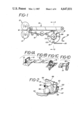
- FIG. 1 is a side elevational view, partly schematic, illustrating apparatus according to the present invention
- FIGS. 1A-1D are schematic perspective views of a sequence of steps performed by the apparatus of FIG. 1;
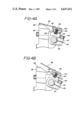
- FIG. 2 is an enlarged fragmentary side elevational view of a gripper finger assembly means, an anvil means, and an actuator means, as seen generally along line 2--2 in FIG. 3, with a portion of the cam in section;
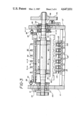
- FIG. 3 is a transverse sectional view, taken generally along line 3--3 in FIG. 1, showing particularly the arrangement of the gripping means;
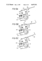
- FIGS. 4A and 4B are enlarged sectional views, taken generally along line 4--4 in FIG. 3, showing the gripper finger assembly means pivoted into and out of contact, respectively, with the gripping surface of an anvil means;
- FIGS. 5A, 5B, and 5C are enlarged sectional views taken generally along line 5--5 in FIG. 3, illustrating the gripper finger in its neutral position, in a position moved toward the anvil means, and in a position moved away from the anvil means, respectively.
- a series of web products such as plastic bags B, are formed by cutting the web with a knife roll 12 operating against an anvil roll 13. After a bag is formed, it enters a conveyor generally designated 14 which includes an upper belt run 15 and a lower belt run 16.
- the belts 15 and 16 are preferably operated at a faster speed than the speed of the web entering the cut-off station. This results in the bags being spaced apart, as shown in FIG. 1B.
- the upper belt 15 is made of screen-type material which runs under a vacuum box or manifold 17.
- the bags are delivered to a first gripping means, generally designated 18, which is made up of a plurality of grippers 19.
- the grippers sequentially grip the bags B in the transport path defined by the belt system 14 and move the bags in sequence around an arcuate path for deposit on a stacking surface 20.
- a guide 92 assists in depositing the bags smoothly on the surface 20.
- an appropriate detector responsive to rotation sensor 99 causes the stack of bags to be removed from surface 20 by a transport (not shown, permitting a new stacking to be initiated.
- the numeral 77 designates a driven shaft, rotatably mounted in the frame elements 10 and 10'.
- the gear drive to this shaft is omitted from FIG. 3, but may include a gear train cooperating with gear 79 which is mounted on the end of gripper shaft 77.
- a pair of spiders 80 mounted on the shaft 77, carry four anvil supports 81, positioned 90 degrees apart.
- Each anvil support 81 in turn, carries a plurality of anvils 82 and block 83 which support actuation shaft 84 carried by a block 83. Clamped to the shaft 84 at each end is a cam follower arm 85 carrying a cam follower 86.
- each gripper finger 88 cooperates with an associated anvil 82 in gripping web products.
- each anvil 82 has a notch at the upper portion thereof confronting the finger 88, which notch includes a pad 89 defining a gripping surface.
- the cam 90 which actuates the cam follower 86 is shown in fragmentary form in FIG. 2.
- the cam 90 operates against the right hand cam follower 86, as seen in FIG. 3, to close the gripper fingers 88 against the pad 89.
- the cam follower 86 operates against a cam 91 on the left hand side of FIG. 3 to open the gripper fingers 88, and thus release the web product onto the surface 20.
- the positions of cams 90 and 91 may be independently adjusted to control independently the opening and closing of the grippers.
- the finger actuator means including actuator shaft 84 pivots the finger support means 87 between an open position, shown in FIG. 4B, and a closed position, shown in FIG. 4A, in which a product is gripped between the pad 89 and the finger 88.
- the finger support means 87 defines a slot 150 which is bridged by bolt 152.
- Bolt 152 when tightened, presses together opposite sides of the slot 150 and thereby secures means 87 to shaft 84.
- Shaft 84 also has associated with it a key 154 which ensures that the finger support means 87 pivots with the shaft 84.
- FIG. 5A illustrates the finger 88 in its neutral position with respect to the finger support means 87;
- FIG. 5B illustrates the finger 88 moved out of the neutral position in a direction generally toward the anvil 82; and
- FIG. 5C illustrates the finger 88 moved out of the neutral position in a direction generally away from the anvil 82.
- the finger support means includes a pair of pivot posts 156 and 158 which extend generally parallel to the axis of the shaft 84, completely through support 87.
- the gripper finger 88 includes a pair of plates 160 which are disposed on either side of the finger support means 87 and which define openings 162 and 164 through which the ends of pivot posts 156 and 158 extend, respectively.
- openings 162 and 164 are larger than posts 156 and 158, whereby relative movement between the gripper finger 88 and the finger support means 87 is permitted by the relative movement of either of the posts 156 or 158 within the openings 162 and 164. This is best seen in FIGS. 5B and 5C.
- the gripper finger assembly further includes a compression spring 166 which engages the finger 88 and the support means 87, and spring biases the finger 88 into its neutral position.
- Spring 166 is compressed between support 87 and finger 88, and positions posts 156 and 158 against the sides of the respective openings 162 and 164 closest to the shaft 84, as shown in FIG. 5A.
- finger 88 For finger 88 to be deflected out of its neutral position, a deflection force must be applied to the finger 88 which overcomes the opposing force of the spring 166, and this must occur before any movement is produced. It will be further appreciated that the movement of finger 88 in either of the two directions is generally a pivoting type movement, and that this movement involves pivoting of finger 88 about the post 158 when the movement is generally toward the anvil, as shown in FIG. 5B, and pivoting of finger 88 about the post 156 when the movement of the finger 88 is generally away from the anvil. Since the spring 166 is positioned intermediate the posts 158 and 156, it opposes movement of the finger 88 in either direction by applying substantially the same force moment to the finger 88.
- the force levels required for deflection of the finger 88 in either direction may generally be set at predetermined desired levels. It should also be noted that the openings 162 and 164 may be sized to provide for differing ranges of motion of the finger 88 in the two directions.
Abstract
Description
Claims (12)
Priority Applications (1)
| Application Number | Priority Date | Filing Date | Title |
|---|---|---|---|
| US06/757,712 US4647031A (en) | 1985-07-22 | 1985-07-22 | Gripper finger device |
Applications Claiming Priority (1)
| Application Number | Priority Date | Filing Date | Title |
|---|---|---|---|
| US06/757,712 US4647031A (en) | 1985-07-22 | 1985-07-22 | Gripper finger device |
Publications (1)
| Publication Number | Publication Date |
|---|---|
| US4647031A true US4647031A (en) | 1987-03-03 |
Family
ID=25048902
Family Applications (1)
| Application Number | Title | Priority Date | Filing Date |
|---|---|---|---|
| US06/757,712 Expired - Fee Related US4647031A (en) | 1985-07-22 | 1985-07-22 | Gripper finger device |
Country Status (1)
| Country | Link |
|---|---|
| US (1) | US4647031A (en) |
Cited By (10)
| Publication number | Priority date | Publication date | Assignee | Title |
|---|---|---|---|---|
| US4719854A (en) * | 1985-08-19 | 1988-01-19 | M.A.N.-Roland Druckmaschinen Aktiengesellschaft | Resilient sheet gripper for a sheet-fed rotary printing press |
| US4947748A (en) * | 1988-06-24 | 1990-08-14 | Heidelberger Druckmaschinen Ag | Sheet gripper on sheet-fed rotary printing presses |
| US5185987A (en) * | 1991-11-01 | 1993-02-16 | Dowbrands Inc | Apparatus for transferring stacks of flexible products |
| US5199757A (en) * | 1990-08-18 | 1993-04-06 | Man Miller Druckmaschinen Gmbh | Gripper finger for the gripper spindle of a sheet-fed printing press |
| US5201516A (en) * | 1992-05-07 | 1993-04-13 | Xerox Corporation | Sheet gripping apparatus |
| US5303650A (en) * | 1991-08-22 | 1994-04-19 | Koenig & Bauer Aktiengesellschaft | Sheet gripper assembly |
| US5393047A (en) * | 1992-09-21 | 1995-02-28 | Xerox Corporation | Sheet gripping mechanism |
| US6213459B1 (en) * | 1998-07-10 | 2001-04-10 | Heidelberger Druckmaschinen Ag | Signature gripper and delivery device |
| US20080290594A1 (en) * | 2007-05-24 | 2008-11-27 | Heidelberger Druckmaschinen Ag | Transfer Drum for Conveying a Sheet in a Machine of the Graphic Arts Industry |
| WO2013083454A1 (en) * | 2011-12-08 | 2013-06-13 | manroland sheetfed GmbH | Sheet-guiding cylinder having a gripper device |
Citations (13)
| Publication number | Priority date | Publication date | Assignee | Title |
|---|---|---|---|---|
| US2530412A (en) * | 1947-12-09 | 1950-11-21 | American Can Co | Conveyer with toggle locking feed dog |
| US2773585A (en) * | 1953-07-27 | 1956-12-11 | Champlain Company Inc | Single chain gripper |
| US2935937A (en) * | 1957-10-29 | 1960-05-10 | Davidson Corp | Plate clamp for printing machine |
| US3148878A (en) * | 1962-04-02 | 1964-09-15 | Xerox Corp | Sheet feed mechanism |
| US3269524A (en) * | 1963-10-24 | 1966-08-30 | Bartelt Engineering Co Inc | Bag clamp |
| US3534683A (en) * | 1967-03-25 | 1970-10-20 | Heidelberger Druckmasch Ag | Color printing rotary press with a match correction device in a transfer drum |
| US3955667A (en) * | 1974-05-28 | 1976-05-11 | Ferag Ag | Endless conveyor with gripping elements |
| US4031824A (en) * | 1975-11-03 | 1977-06-28 | American Screen Printing Equipment Company | Sheet feed and takeoff assembly for printers |
| US4058307A (en) * | 1975-11-03 | 1977-11-15 | American Screen Printing Equipment Company | Feed and takeoff assembly |
| US4284301A (en) * | 1979-04-09 | 1981-08-18 | The Dow Chemical Company | Bag transfer device |
| US4358466A (en) * | 1980-04-11 | 1982-11-09 | The Dow Chemical Company | Freezer to microwave oven bag |
| US4372209A (en) * | 1980-11-17 | 1983-02-08 | Veb Kombinat Polygraph "Werner Lamberz" | Sheet gripping jar arrangement |
| US4381056A (en) * | 1980-02-08 | 1983-04-26 | Ferag Ag | Conveyor apparatus, especially for printed products |
-
1985
- 1985-07-22 US US06/757,712 patent/US4647031A/en not_active Expired - Fee Related
Patent Citations (14)
| Publication number | Priority date | Publication date | Assignee | Title |
|---|---|---|---|---|
| US2530412A (en) * | 1947-12-09 | 1950-11-21 | American Can Co | Conveyer with toggle locking feed dog |
| US2773585A (en) * | 1953-07-27 | 1956-12-11 | Champlain Company Inc | Single chain gripper |
| US2935937A (en) * | 1957-10-29 | 1960-05-10 | Davidson Corp | Plate clamp for printing machine |
| US3148878A (en) * | 1962-04-02 | 1964-09-15 | Xerox Corp | Sheet feed mechanism |
| US3269524A (en) * | 1963-10-24 | 1966-08-30 | Bartelt Engineering Co Inc | Bag clamp |
| US3534683A (en) * | 1967-03-25 | 1970-10-20 | Heidelberger Druckmasch Ag | Color printing rotary press with a match correction device in a transfer drum |
| US3955667A (en) * | 1974-05-28 | 1976-05-11 | Ferag Ag | Endless conveyor with gripping elements |
| US4031824A (en) * | 1975-11-03 | 1977-06-28 | American Screen Printing Equipment Company | Sheet feed and takeoff assembly for printers |
| US4058307A (en) * | 1975-11-03 | 1977-11-15 | American Screen Printing Equipment Company | Feed and takeoff assembly |
| US4284301A (en) * | 1979-04-09 | 1981-08-18 | The Dow Chemical Company | Bag transfer device |
| US4381056A (en) * | 1980-02-08 | 1983-04-26 | Ferag Ag | Conveyor apparatus, especially for printed products |
| US4381056B1 (en) * | 1980-02-08 | 1989-07-25 | ||
| US4358466A (en) * | 1980-04-11 | 1982-11-09 | The Dow Chemical Company | Freezer to microwave oven bag |
| US4372209A (en) * | 1980-11-17 | 1983-02-08 | Veb Kombinat Polygraph "Werner Lamberz" | Sheet gripping jar arrangement |
Cited By (10)
| Publication number | Priority date | Publication date | Assignee | Title |
|---|---|---|---|---|
| US4719854A (en) * | 1985-08-19 | 1988-01-19 | M.A.N.-Roland Druckmaschinen Aktiengesellschaft | Resilient sheet gripper for a sheet-fed rotary printing press |
| US4947748A (en) * | 1988-06-24 | 1990-08-14 | Heidelberger Druckmaschinen Ag | Sheet gripper on sheet-fed rotary printing presses |
| US5199757A (en) * | 1990-08-18 | 1993-04-06 | Man Miller Druckmaschinen Gmbh | Gripper finger for the gripper spindle of a sheet-fed printing press |
| US5303650A (en) * | 1991-08-22 | 1994-04-19 | Koenig & Bauer Aktiengesellschaft | Sheet gripper assembly |
| US5185987A (en) * | 1991-11-01 | 1993-02-16 | Dowbrands Inc | Apparatus for transferring stacks of flexible products |
| US5201516A (en) * | 1992-05-07 | 1993-04-13 | Xerox Corporation | Sheet gripping apparatus |
| US5393047A (en) * | 1992-09-21 | 1995-02-28 | Xerox Corporation | Sheet gripping mechanism |
| US6213459B1 (en) * | 1998-07-10 | 2001-04-10 | Heidelberger Druckmaschinen Ag | Signature gripper and delivery device |
| US20080290594A1 (en) * | 2007-05-24 | 2008-11-27 | Heidelberger Druckmaschinen Ag | Transfer Drum for Conveying a Sheet in a Machine of the Graphic Arts Industry |
| WO2013083454A1 (en) * | 2011-12-08 | 2013-06-13 | manroland sheetfed GmbH | Sheet-guiding cylinder having a gripper device |
Similar Documents
| Publication | Publication Date | Title |
|---|---|---|
| US6128887A (en) | Method for packaging flat articles | |
| US4284301A (en) | Bag transfer device | |
| EP0619227B1 (en) | Process and machine for wrapping products with stretchable film | |
| EP0919471B1 (en) | Device for handling packages | |
| US4647031A (en) | Gripper finger device | |
| US5460479A (en) | Signature stacking machine | |
| US4482141A (en) | Method and apparatus for conveying folded sheets using orbitally gripping and releasing clamp pads | |
| CA1193625A (en) | Apparatus for transporting continuously arriving flat paper products, especially a stream of printed products arriving in an imbricated formation | |
| US3982749A (en) | Signature feeder | |
| GB2102393A (en) | High speed transport system for newspapers and the like | |
| US6238173B1 (en) | Apparatus for placing groups of products on pallets | |
| ES355755A1 (en) | Stacking apparatus for plastics material sheeting | |
| US5992610A (en) | Method and device for producing a rotated stream with a corner gripper | |
| CA1282365C (en) | Method and apparatus for turning continuously conveyed flat structures, especially arriving imbricated printed products such as to retain their original imbricated formation | |
| US4899518A (en) | Envelope packing apparatus | |
| US4930977A (en) | Envelope handling system | |
| JPH0355383B2 (en) | ||
| US4905986A (en) | Transport apparatus for flat products with individually controllable grippers | |
| US4270908A (en) | Apparatus for the stacking and connection of synthetic-resin foil or sheet bags | |
| US5740900A (en) | Apparatus for splitting a product stream | |
| US5088720A (en) | Envelope handling system | |
| US6851544B2 (en) | Transfer device | |
| US7380336B2 (en) | Gripping system | |
| US6349933B1 (en) | Method and apparatus for horizontal stacking and batching of sheet products | |
| EP0412080B1 (en) | Package positioning apparatus and method |
Legal Events
| Date | Code | Title | Description |
|---|---|---|---|
| AS | Assignment |
Owner name: DOW CHEMICAL COMPANY, THE, Free format text: ASSIGNMENT OF ASSIGNORS INTEREST.;ASSIGNORS:SMITH, DAVID A.;GEIGER, HERBERT B.;REEL/FRAME:004630/0130 Effective date: 19860719 |
|
| FEPP | Fee payment procedure |
Free format text: PAYOR NUMBER ASSIGNED (ORIGINAL EVENT CODE: ASPN); ENTITY STATUS OF PATENT OWNER: LARGE ENTITY |
|
| FPAY | Fee payment |
Year of fee payment: 4 |
|
| AS | Assignment |
Owner name: DOWBRANDS INC., INDIANA Free format text: ASSIGNMENT OF ASSIGNORS INTEREST.;ASSIGNOR:DOW CHEMICAL COMPANY, THE;REEL/FRAME:005755/0625 Effective date: 19910619 |
|
| AS | Assignment |
Owner name: DOWBRANDS L.P., INDIANA Free format text: ASSIGNMENT OF ASSIGNORS INTEREST.;ASSIGNOR:DOWBRANDS INC., A CORP. OF DE;REEL/FRAME:006021/0052 Effective date: 19911218 |
|
| REMI | Maintenance fee reminder mailed | ||
| LAPS | Lapse for failure to pay maintenance fees | ||
| FP | Lapsed due to failure to pay maintenance fee |
Effective date: 19950308 |
|
| STCH | Information on status: patent discontinuation |
Free format text: PATENT EXPIRED DUE TO NONPAYMENT OF MAINTENANCE FEES UNDER 37 CFR 1.362 |