US4635478A - Device for registration of level, transition zones and temperature - Google Patents
Device for registration of level, transition zones and temperature Download PDFInfo
- Publication number
- US4635478A US4635478A US06/616,830 US61683084A US4635478A US 4635478 A US4635478 A US 4635478A US 61683084 A US61683084 A US 61683084A US 4635478 A US4635478 A US 4635478A
- Authority
- US
- United States
- Prior art keywords
- probe
- tape measure
- manually operable
- measuring apparatus
- media
- Prior art date
- Legal status (The legal status is an assumption and is not a legal conclusion. Google has not performed a legal analysis and makes no representation as to the accuracy of the status listed.)
- Expired - Fee Related
Links
Images


Classifications
-
- G—PHYSICS
- G01—MEASURING; TESTING
- G01F—MEASURING VOLUME, VOLUME FLOW, MASS FLOW OR LIQUID LEVEL; METERING BY VOLUME
- G01F23/00—Indicating or measuring liquid level or level of fluent solid material, e.g. indicating in terms of volume or indicating by means of an alarm
- G01F23/22—Indicating or measuring liquid level or level of fluent solid material, e.g. indicating in terms of volume or indicating by means of an alarm by measuring physical variables, other than linear dimensions, pressure or weight, dependent on the level to be measured, e.g. by difference of heat transfer of steam or water
- G01F23/24—Indicating or measuring liquid level or level of fluent solid material, e.g. indicating in terms of volume or indicating by means of an alarm by measuring physical variables, other than linear dimensions, pressure or weight, dependent on the level to be measured, e.g. by difference of heat transfer of steam or water by measuring variations of resistance of resistors due to contact with conductor fluid
- G01F23/245—Indicating or measuring liquid level or level of fluent solid material, e.g. indicating in terms of volume or indicating by means of an alarm by measuring physical variables, other than linear dimensions, pressure or weight, dependent on the level to be measured, e.g. by difference of heat transfer of steam or water by measuring variations of resistance of resistors due to contact with conductor fluid with a probe moved by an auxiliary power, e.g. meter, to follow automatically the level
-
- G—PHYSICS
- G01—MEASURING; TESTING
- G01F—MEASURING VOLUME, VOLUME FLOW, MASS FLOW OR LIQUID LEVEL; METERING BY VOLUME
- G01F23/00—Indicating or measuring liquid level or level of fluent solid material, e.g. indicating in terms of volume or indicating by means of an alarm
- G01F23/0023—Indicating or measuring liquid level or level of fluent solid material, e.g. indicating in terms of volume or indicating by means of an alarm with a probe suspended by a wire or thread
-
- G—PHYSICS
- G01—MEASURING; TESTING
- G01F—MEASURING VOLUME, VOLUME FLOW, MASS FLOW OR LIQUID LEVEL; METERING BY VOLUME
- G01F23/00—Indicating or measuring liquid level or level of fluent solid material, e.g. indicating in terms of volume or indicating by means of an alarm
- G01F23/22—Indicating or measuring liquid level or level of fluent solid material, e.g. indicating in terms of volume or indicating by means of an alarm by measuring physical variables, other than linear dimensions, pressure or weight, dependent on the level to be measured, e.g. by difference of heat transfer of steam or water
- G01F23/26—Indicating or measuring liquid level or level of fluent solid material, e.g. indicating in terms of volume or indicating by means of an alarm by measuring physical variables, other than linear dimensions, pressure or weight, dependent on the level to be measured, e.g. by difference of heat transfer of steam or water by measuring variations of capacity or inductance of capacitors or inductors arising from the presence of liquid or fluent solid material in the electric or electromagnetic fields
- G01F23/263—Indicating or measuring liquid level or level of fluent solid material, e.g. indicating in terms of volume or indicating by means of an alarm by measuring physical variables, other than linear dimensions, pressure or weight, dependent on the level to be measured, e.g. by difference of heat transfer of steam or water by measuring variations of capacity or inductance of capacitors or inductors arising from the presence of liquid or fluent solid material in the electric or electromagnetic fields by measuring variations in capacitance of capacitors
- G01F23/268—Indicating or measuring liquid level or level of fluent solid material, e.g. indicating in terms of volume or indicating by means of an alarm by measuring physical variables, other than linear dimensions, pressure or weight, dependent on the level to be measured, e.g. by difference of heat transfer of steam or water by measuring variations of capacity or inductance of capacitors or inductors arising from the presence of liquid or fluent solid material in the electric or electromagnetic fields by measuring variations in capacitance of capacitors mounting arrangements of probes
-
- Y—GENERAL TAGGING OF NEW TECHNOLOGICAL DEVELOPMENTS; GENERAL TAGGING OF CROSS-SECTIONAL TECHNOLOGIES SPANNING OVER SEVERAL SECTIONS OF THE IPC; TECHNICAL SUBJECTS COVERED BY FORMER USPC CROSS-REFERENCE ART COLLECTIONS [XRACs] AND DIGESTS
- Y10—TECHNICAL SUBJECTS COVERED BY FORMER USPC
- Y10T—TECHNICAL SUBJECTS COVERED BY FORMER US CLASSIFICATION
- Y10T137/00—Fluid handling
- Y10T137/8158—With indicator, register, recorder, alarm or inspection means
- Y10T137/8342—Liquid level responsive indicator, recorder or alarm
Definitions
- the present invention relates to a device for measuring, by means of a manually operable portable measuring apparatus, the physical properties of the contents of the tank, said device including a probe being sensitive to the medium to be measured, said probe being connected to a reel means through a tape measure having means for positional read-off.
- the present invention is therefore intended to record the transition between liquid and gas, and/or the transition layer between two liquids or other medium to be measured.
- the present invention to be described further solves the problem of detection of level and transition layers by providing high accuracy, independently of the nature of the medium to be measured. Simultaneously, the effect of hysteresis is minor, and there are no cleaning problems, in addition to the fact that three properties may be measured by one single probe. Further, the probe is capable of being adjusted such that it may record an interface between two media without the body of the probe touching said interface.
- the device consists of a manually operable apparatus having a reel upon which is wound a graded tape measure having integrally connected therewith electrical conductors.
- the combination probe is attached to the free end of the tape measure, said probe being capable of registrating a sharp and well-defined interface between gas and liquid as well as a mixed transition layer between two liquids by means of a sensing device responsive to the electrical properties of the ambient measuring medium, in particular dielectric constant and loss factor.
- the temperature is recorded by means of a temperature sensitive current generator or modifier. An indication of the probe reaching the liquid surface or possibly the mixed transition layer between two liquids, appears either as an acoustic signal from an audio signal transmitter arranged at the center of the said reel means or as change in current being registered on a suitable indicator.
- the temperature may be read off on a display together with or combined with the means for reading off the other parameters arranged at the center of said reel.
- the actual position of the tip of the probe may be read off on the tape measure by means of a suitable indicator.
- the present device is particularly suitable in cases where the medium to be measured is of such nature that the probe is not capable of penetrating into the medium. This may be the case with high-viscosity liquids, particles or medium being of such a nature that it is not of advantage to have contact between the probe and the medium to be measured, or that the medium is of such a nature that a change in dielectric constant or loss factor is the most suitable or the only method for recording a transition layer.
- FIG. 1 shows a section through the manually operable apparatus according to the invention
- FIG. 2 shows a front view of the manually operable apparatus of FIG. 1,
- FIG. 3 is a valve device adapted to cooperate with the sluice of the manually operable apparatus illustrated in FIGS. 1 and 2;
- FIG. 4 shows a scrape-off means which cooperates with tape measure and is capable of draining off possible electrostatic charges created in connection with unwinding of the tape;
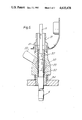
- FIG. 5 is a view in cross section illustrating in detail the sluice/valve element of the embodiment of the inventive apparatus shown in FIG. 3;
- FIG. 6a shows the relationship of the probe and tape measure in the apparatus of this invention
- FIG. 6b shows in detailed block diagrammatic form the electronic circuitry of the probe
- FIG. 7a is a lateral view in elevation of the control and monitoring element of the apparatus of this invention.
- FIG. 7b shows in detailed block diagrammatic form the electronic circuitry of the control and monitoring element illustrated in FIG. 7a;
- FIG. 7c shows schematically a tank, tank top, ullage level, first and second liquid levels, levels preselected for temperature readings, an interface level between the liquids, a gas level and a probe in accordance with the invention inserted in the tank;
- FIG. 7c shows the probe measuring the physical properties of the two liquids.
- FIGS. 8 and 9 illustrate two alternative embodiments of the tape measure employed in the inventive apparatus, including illustrations of the conductor cables integrated therein.
- the diameter of the probe is quite small compared to the size of the tank, suitably being 1 inch (25 mm) which enables measurements to be made in tanks and containers having a pressure different from the atmospheric by letting the probe be introduced through a sluice means.
- the manually operable device is illustrated in FIG. 1.
- the reel 2 is pivotably connected to a holder 1 on support.
- a lock means 3 serves to lock the reel 2 in any position and thereby prevents the measurement probe 4 from dropping in an uncontrolled manner from the sluice 5.
- the sluice is connected to the top of a valve means 30 (see FIG. 3) by means of a quick-coupling 6.
- a combined scrape-off, sealing and electric drain device 13 is mounted between said sluice 5 and the holder 1, and being disconnectable by means of a coupling 14 for replacement or cleaning.
- the scrape-off device 13 is capable of draining off possible electrostatic charges which may have been created in connection with the unwinding of the tape measure.
- the tape measure 11 is wound on the reel 2.
- Winding and unwinding of the tape measure is carried out by means of turning the handle 12 fixed to reel 2.
- a monitoring unit 15 having a battery means and the required electronics is mounted at the centre of the reel 2 with an electrical connection to the tape measure 11 which itself is fixed to the reel 2 and also has a connection to ground.
- FIG. 2 the device is shown in frontal view having the tape measure 11 running across a guide means 20 which is provided with alignment marks 21 to indicate the exact position of the combination probe relative to a reference point of the tank.
- FIG. 3 illustrates the valve means 30 with its connector 31.
- a valve handle 32 opens and closes the passage through the valve means by means of the ball 33.
- the complete valve means is connected to the tank by means of a threaded portion 34.
- FIG. 4 illustrates in further details the scrape-off device 13 having a guide hole 40, the circumference of which encompasses the tape measure 11, a slit 41 being provided for lateral introduction of the tape.
- the scrape-off device 13 may be arranged at the upper end of the sluice 5 for said probe. It may consist of a piece of elastic plastic material to which has been added sufficient conductive material so as to obtain a close fit against the tape measure as well as a sufficient conductivity. As indicated in FIG. 4, the scrape-off device 13 may be composed of one or two parts.
- a guide sleeve 50 When introducing the probe 4 from the sluice through the ball valve means 30 into the tank, it may be advantageous to provide a guide sleeve 50.
- the said sleeve 50 is retained at the upper portion of the sluice 5 by resting on the probe 4.
- the sleeve 50 follows in order to prevent the valve ball 33 from damaging the tape measure 11.
- the sleeve 50 is provided with a collar 51 which comes to rest against a stop means 52 at the lower-most position thereof, as clearly indicated in FIG. 5.
- the sleeve may, in addition to serve as guidance for the tape measure, be provided with drain-off electrodes for possible electrostatic charges.
- the said sleeve will upon introduction into the housing of the valve means 30 provide both a guidance for the tape measure as well as protection against wear thereof due to sharp edges within the valve housing. Further, as will clearly appear from FIG. 5, the protective sleeve 50 also safeguards against any damage or accidental cutting-off in connection with closing of the ball valve before the probe is completely withdrawn into the sluice.
- FIGS. 6a and b there is illustrated a combination measurement probe 4 being surrounded by an acid-proof steel tube, the interior of which is filled with an insulating material in order to stabilize and protect electronic components (65 therein), the tip 60 of the probe being made from an insulating material and forming the sensitive end reacting to changes in dielectric constant and the loss factor of the medium.
- the probe 4 is connected to the tape measure 11 both in a mechanical and electrical fashion.
- the sensitive end of the probe 4 can be made from a non-conductive plastic material in which the capacitive sensor part 69 has been embedded. As indicated in FIG.
- the diode 67 which in turn charges a capacitor 68.
- the value of the D.C. voltage of the capacitor 68 determines the characteristics of pulse modulated signal which is superimposed by the electronic circuit 65 on the supplied power supply current and detected by the monitoring part at the centre of the reel after transfer via the conductors of the tape measure 11. Both the energy supply as well as the transfer of the measurement signal may take place through three conductors.
- a temperature sensitive device 62 may be arranged close to the capacitive sensor part 69 and function as a current generator or modifier where the current is proportional to the temperature in degrees Kelvin. Its current path is through the conductors 63 and it is separated from the capacitance and capacitive sensor part 69 by means of a diode 64.
- FIGS. 7a and 7b illustrate both in elevation and in schematic form the control- and monitor part 15 having a battery 70 and a digital display 71 which in the example in FIG. 7a displays the temperature of the medium which is sensed.
- the current generated in the temperature sensor 62 is a function of the temperature in degrees Kelvin surrounding the sensor, and is by means of an adaptation circuit 75 transformed into a degree definition on the said display 71.
- the resistors 76 and 77 serve as current limiters in connection with use in surroundings where the risk of explosion is high.
- a timer 73 is started by means of push-button 72 for a specific period of time whereby power supply to the measurement probe takes place via the conductors of the tape measure 11.
- the measurement signal from the ullage/interface sensor electronic circuit 65 is transferred as short pulses superimposed upon the power supply current, and is decoded and converted into acoustic signals in a converter 74.
- FIG. 8 illustrates the tape measure 11 which is made with an insulation mantle 80, surrounding a steel tape measure 11' being graded into suitable measurement units, and with the largest measurement unit repeated often enough that in any position for the operation of the tape measure, it is possible to read off both the largest unit, for instance meters (SI-limit) as well as centimeters and millimeters, within a distance on the tape measure of 5-10 cm.
- the steel tape 11' also functions to form an earth connection connecting the combination sensor galvanically to the earth reference of the tank and to compensate for strain.
- Two or more electrical conductors or cables 81, 82 may be integrated in the tape measure 11 and be independently insulated.
- the said conductors may have a rectangular cross-section as indicated in FIG. 8, e.g. in the form of longitudinal foils with sufficient distance from the marginal edge of the steel tape 11' to prevent the conductors from being exposed to the environment due to mechanical wear or other form of damage on the edges of the tape measure 11.
- the tape measure 11 may be provided with conductors 90 of circular cross-section, the number of conductors being four in the non-limitative example.
Abstract
Description
Claims (13)
Applications Claiming Priority (2)
| Application Number | Priority Date | Filing Date | Title |
|---|---|---|---|
| NO823167A NO156305C (en) | 1982-09-17 | 1982-09-17 | DEVICE FOR REGISTRATION OF NIVAA, TRANSITIONAL ZONES AND TEMPERATURE. |
| NO823167 | 1982-09-17 |
Publications (1)
| Publication Number | Publication Date |
|---|---|
| US4635478A true US4635478A (en) | 1987-01-13 |
Family
ID=19886715
Family Applications (1)
| Application Number | Title | Priority Date | Filing Date |
|---|---|---|---|
| US06/616,830 Expired - Fee Related US4635478A (en) | 1982-09-17 | 1983-09-16 | Device for registration of level, transition zones and temperature |
Country Status (10)
| Country | Link |
|---|---|
| US (1) | US4635478A (en) |
| EP (1) | EP0118523A1 (en) |
| JP (1) | JPS59501757A (en) |
| CA (1) | CA1215555A (en) |
| DK (1) | DK106884A (en) |
| ES (1) | ES525671A0 (en) |
| FI (1) | FI841937A0 (en) |
| IT (1) | IT1166953B (en) |
| NO (1) | NO156305C (en) |
| WO (1) | WO1984001216A1 (en) |
Cited By (15)
| Publication number | Priority date | Publication date | Assignee | Title |
|---|---|---|---|---|
| US4977786A (en) * | 1990-01-18 | 1990-12-18 | E. I. Du Pont De Nemours And Company | Capacitive liquid level sensor |
| US5012589A (en) * | 1989-06-16 | 1991-05-07 | Magnetrol International | Displacement servo gauge |
| US5012683A (en) * | 1990-01-18 | 1991-05-07 | E. I. Dupont De Nemours And Company | Capacitive liquid interface sensor |
| US5036703A (en) * | 1989-02-23 | 1991-08-06 | Eriksson Bror Allan | Method and apparatus for testing liquid fillings in tanks |
| US5083470A (en) * | 1990-01-18 | 1992-01-28 | E. I. Du Pont De Nemours And Company | Capacitive liquid level sensor |
| EP0767897A1 (en) * | 1994-06-29 | 1997-04-16 | Alcoa Of Australia Limited | Thickener mud gauge |
| US6148666A (en) * | 1997-10-29 | 2000-11-21 | Boehringer Mannheim Gmbh | Method and device for liquid transfer with an analysis apparatus |
| US6551558B1 (en) | 1999-04-28 | 2003-04-22 | Roche Diagnostics Gmbh | Method and device for liquid transfer with an analysis apparatus |
| US20040065148A1 (en) * | 2002-10-07 | 2004-04-08 | Ham Eric R. | Stratified hot water heated depth display system |
| US20100155066A1 (en) * | 2008-12-24 | 2010-06-24 | Victor Fordyce | Proppant control in an lpg frac system |
| US7938002B1 (en) * | 2007-05-25 | 2011-05-10 | Ernesto Lazos | Apparatus for detecting water level mixtures in fluids |
| US20140104098A1 (en) * | 2012-10-16 | 2014-04-17 | Magnetrol International, Incorporated | Guided wave radar interface measurement medium identification |
| US8832957B2 (en) | 2012-07-26 | 2014-09-16 | Caterpillar Inc. | Apparatus and method for determining ash height in a filter |
| US10055519B2 (en) * | 2014-10-23 | 2018-08-21 | Honeywell International Inc. | Pulse shape change for interface determination |
| US10981162B2 (en) * | 2016-07-22 | 2021-04-20 | Tecan Trading Ag | Pipetting device having a pipette tip detection unit and method for detecting a pipette tip on a pipetting device |
Families Citing this family (2)
| Publication number | Priority date | Publication date | Assignee | Title |
|---|---|---|---|---|
| NO308333B2 (en) * | 1997-04-08 | 2000-08-28 | Sentech As | Device for capacitive electrical detection or painting |
| US7191647B2 (en) | 2003-10-30 | 2007-03-20 | Perkinelmer Las, Inc. | Method and apparatus to reject electrical interference in a capacitive liquid level sensor system |
Citations (7)
| Publication number | Priority date | Publication date | Assignee | Title |
|---|---|---|---|---|
| US812269A (en) * | 1905-05-17 | 1906-02-13 | Daniel L Mott | Water-level-gaging instrument. |
| US2284396A (en) * | 1942-05-26 | Gauging and sampling apparatus fob | ||
| US3098914A (en) * | 1961-04-27 | 1963-07-23 | Amedio W Giannino | Oil level warning devices |
| US3500546A (en) * | 1967-09-20 | 1970-03-17 | Harold Pilcher | Automatic container storage level container |
| DE2743862A1 (en) * | 1976-09-29 | 1978-03-30 | Marine Marine Moisture Control | EMPTY SPACE MEASURING DEVICE |
| US4226023A (en) * | 1979-04-11 | 1980-10-07 | Marine Moisture Control Company, Inc. | Portable device for determining physical qualities of pressurized container contents |
| US4255859A (en) * | 1979-05-07 | 1981-03-17 | Berwind Corporation | Drop-weight material level indicator |
Family Cites Families (13)
| Publication number | Priority date | Publication date | Assignee | Title |
|---|---|---|---|---|
| US1947592A (en) * | 1930-04-14 | 1934-02-20 | John F Haller | Combination gauge bob and thermometer |
| US2677276A (en) * | 1948-07-26 | 1954-05-04 | Cutler Hammer Inc | Liquid level and temperature indicating apparatus |
| US2627660A (en) * | 1950-02-27 | 1953-02-10 | Philip N Smith | Liquid depth measuring device |
| US3473380A (en) * | 1967-12-28 | 1969-10-21 | Sun Oil Co | Liquid level measuring apparatus |
| US3653262A (en) * | 1970-10-22 | 1972-04-04 | Metritake Inc | Temperature and level sensor |
| US3728897A (en) * | 1970-11-16 | 1973-04-24 | Cons Airborne Systems | Compensated fuel gage |
| JPS5428961B2 (en) * | 1973-08-08 | 1979-09-20 | ||
| JPS5231289U (en) * | 1975-08-27 | 1977-03-04 | ||
| YU135278A (en) * | 1978-06-06 | 1982-06-30 | Energoinvest | Resonance apparatus for measuring the level |
| YU135178A (en) * | 1978-06-06 | 1982-06-30 | Energoinvest | Ia resonance apparatus for signalling the level of liquid med |
| US4318227A (en) * | 1979-04-11 | 1982-03-09 | Marine Moisture Control Company, Inc. | Device for determining physical qualities of pressurized container contents |
| FR2454089A1 (en) * | 1979-04-11 | 1980-11-07 | Gaucel Gerard | Volatile liq. quantity measurement method - employing probe on tape measure lowered via valve from sealed enclosure |
| NL8002951A (en) * | 1980-05-21 | 1981-12-16 | Gebhard Electro B V | CAPACITIVE MEASURING DEVICE. |
-
1982
- 1982-09-17 NO NO823167A patent/NO156305C/en not_active IP Right Cessation
-
1983
- 1983-09-16 JP JP58502972A patent/JPS59501757A/en active Pending
- 1983-09-16 IT IT2291083A patent/IT1166953B/en active
- 1983-09-16 ES ES525671A patent/ES525671A0/en active Granted
- 1983-09-16 WO PCT/NO1983/000034 patent/WO1984001216A1/en not_active Application Discontinuation
- 1983-09-16 EP EP83902906A patent/EP0118523A1/en not_active Withdrawn
- 1983-09-16 US US06/616,830 patent/US4635478A/en not_active Expired - Fee Related
- 1983-09-16 CA CA000436888A patent/CA1215555A/en not_active Expired
-
1984
- 1984-02-27 DK DK106884A patent/DK106884A/en not_active Application Discontinuation
- 1984-05-15 FI FI841937A patent/FI841937A0/en not_active Application Discontinuation
Patent Citations (7)
| Publication number | Priority date | Publication date | Assignee | Title |
|---|---|---|---|---|
| US2284396A (en) * | 1942-05-26 | Gauging and sampling apparatus fob | ||
| US812269A (en) * | 1905-05-17 | 1906-02-13 | Daniel L Mott | Water-level-gaging instrument. |
| US3098914A (en) * | 1961-04-27 | 1963-07-23 | Amedio W Giannino | Oil level warning devices |
| US3500546A (en) * | 1967-09-20 | 1970-03-17 | Harold Pilcher | Automatic container storage level container |
| DE2743862A1 (en) * | 1976-09-29 | 1978-03-30 | Marine Marine Moisture Control | EMPTY SPACE MEASURING DEVICE |
| US4226023A (en) * | 1979-04-11 | 1980-10-07 | Marine Moisture Control Company, Inc. | Portable device for determining physical qualities of pressurized container contents |
| US4255859A (en) * | 1979-05-07 | 1981-03-17 | Berwind Corporation | Drop-weight material level indicator |
Cited By (18)
| Publication number | Priority date | Publication date | Assignee | Title |
|---|---|---|---|---|
| US5036703A (en) * | 1989-02-23 | 1991-08-06 | Eriksson Bror Allan | Method and apparatus for testing liquid fillings in tanks |
| US5012589A (en) * | 1989-06-16 | 1991-05-07 | Magnetrol International | Displacement servo gauge |
| US4977786A (en) * | 1990-01-18 | 1990-12-18 | E. I. Du Pont De Nemours And Company | Capacitive liquid level sensor |
| US5012683A (en) * | 1990-01-18 | 1991-05-07 | E. I. Dupont De Nemours And Company | Capacitive liquid interface sensor |
| US5083470A (en) * | 1990-01-18 | 1992-01-28 | E. I. Du Pont De Nemours And Company | Capacitive liquid level sensor |
| EP0767897A1 (en) * | 1994-06-29 | 1997-04-16 | Alcoa Of Australia Limited | Thickener mud gauge |
| EP0767897A4 (en) * | 1994-06-29 | 1998-08-19 | Alcoa Australia | Thickener mud gauge |
| US6148666A (en) * | 1997-10-29 | 2000-11-21 | Boehringer Mannheim Gmbh | Method and device for liquid transfer with an analysis apparatus |
| US6551558B1 (en) | 1999-04-28 | 2003-04-22 | Roche Diagnostics Gmbh | Method and device for liquid transfer with an analysis apparatus |
| US20040065148A1 (en) * | 2002-10-07 | 2004-04-08 | Ham Eric R. | Stratified hot water heated depth display system |
| US6990861B2 (en) * | 2002-10-07 | 2006-01-31 | Ham Eric R | Stratified hot water heated depth display system |
| US7938002B1 (en) * | 2007-05-25 | 2011-05-10 | Ernesto Lazos | Apparatus for detecting water level mixtures in fluids |
| US20100155066A1 (en) * | 2008-12-24 | 2010-06-24 | Victor Fordyce | Proppant control in an lpg frac system |
| US8832957B2 (en) | 2012-07-26 | 2014-09-16 | Caterpillar Inc. | Apparatus and method for determining ash height in a filter |
| US20140104098A1 (en) * | 2012-10-16 | 2014-04-17 | Magnetrol International, Incorporated | Guided wave radar interface measurement medium identification |
| US8963769B2 (en) * | 2012-10-16 | 2015-02-24 | Magnetrol International, Incorporated | Guided wave radar interface measurement medium identification |
| US10055519B2 (en) * | 2014-10-23 | 2018-08-21 | Honeywell International Inc. | Pulse shape change for interface determination |
| US10981162B2 (en) * | 2016-07-22 | 2021-04-20 | Tecan Trading Ag | Pipetting device having a pipette tip detection unit and method for detecting a pipette tip on a pipetting device |
Also Published As
| Publication number | Publication date |
|---|---|
| WO1984001216A1 (en) | 1984-03-29 |
| IT1166953B (en) | 1987-05-06 |
| IT8322910A0 (en) | 1983-09-16 |
| FI841937A (en) | 1984-05-15 |
| DK106884D0 (en) | 1984-02-27 |
| NO156305B (en) | 1987-05-18 |
| CA1215555A (en) | 1986-12-23 |
| NO823167L (en) | 1984-03-19 |
| JPS59501757A (en) | 1984-10-18 |
| ES8405937A1 (en) | 1984-06-16 |
| ES525671A0 (en) | 1984-06-16 |
| DK106884A (en) | 1984-03-29 |
| NO156305C (en) | 1987-08-26 |
| EP0118523A1 (en) | 1984-09-19 |
| FI841937A0 (en) | 1984-05-15 |
Similar Documents
| Publication | Publication Date | Title |
|---|---|---|
| US4635478A (en) | Device for registration of level, transition zones and temperature | |
| CA1232467A (en) | Fluid level gauge having magnetic sensor | |
| US7017409B2 (en) | Proximity sensor for level sensing | |
| CA2115596C (en) | Capacitive proximity monitoring device for corrosive atmosphere environment | |
| CA1042226A (en) | Gauge for remotely indicating the pressure of a subterranean formation | |
| CA1086938A (en) | Ullage measuring device | |
| US6938478B2 (en) | Impedance level meter for liquids in tanks | |
| US5187979A (en) | Multi-sensor probe assembly and method for fuel storage system including overflow protection means | |
| US4864857A (en) | Level indicator | |
| CA1276233C (en) | Method and apparatus for locating leaks in a multiple layer geomembrane | |
| US4188826A (en) | Device for measuring the liquid level of an electrically conductive liquid | |
| US3918306A (en) | System for measuring fluid levels in a vehicle transmission | |
| GB1519661A (en) | Liquid level gauge | |
| US4208909A (en) | Admittance sensing probe having multiple sensing elements | |
| US3367183A (en) | Apparatus for measuring liquid levels | |
| US5237857A (en) | Down-hole liquid detecting apparatus | |
| US4520318A (en) | Electric field strength indicator | |
| US4442405A (en) | Float assembly for a sensor | |
| US5860316A (en) | Capacitance probe | |
| US3950653A (en) | Instrument for sensing level of granular materials | |
| EP0570526B1 (en) | Device and method for detecting the presence of oil on water | |
| CA1108847A (en) | Elevation measuring apparatus | |
| KR101168196B1 (en) | Oil/water interface detector capable of storage tank inside pressure measurement | |
| US5698775A (en) | Device for locating the position of the separation between two mediums, and a receptacle and a detection process employing the device | |
| GB2046912A (en) | A liquid level detector |
Legal Events
| Date | Code | Title | Description |
|---|---|---|---|
| AS | Assignment |
Owner name: TANKSYSTEM A/S, VOLLSVN. 13, P.O. BOX 251, N-1324 Free format text: ASSIGNMENT OF ASSIGNORS INTEREST.;ASSIGNOR:HOPE, BJORN R.;REEL/FRAME:004482/0027 Effective date: 19850628 |
|
| FEPP | Fee payment procedure |
Free format text: PAYOR NUMBER ASSIGNED (ORIGINAL EVENT CODE: ASPN); ENTITY STATUS OF PATENT OWNER: LARGE ENTITY |
|
| FPAY | Fee payment |
Year of fee payment: 4 |
|
| AS | Assignment |
Owner name: MACHAO A.G., SWITZERLAND Free format text: ASSIGNMENT OF ASSIGNORS INTEREST;ASSIGNOR:TANKSYSTEM A/S;REEL/FRAME:006539/0972 Effective date: 19920601 |
|
| FEPP | Fee payment procedure |
Free format text: PAT HLDR NO LONGER CLAIMS SMALL ENT STAT AS SMALL BUSINESS (ORIGINAL EVENT CODE: LSM2); ENTITY STATUS OF PATENT OWNER: LARGE ENTITY |
|
| FPAY | Fee payment |
Year of fee payment: 8 |
|
| REMI | Maintenance fee reminder mailed | ||
| LAPS | Lapse for failure to pay maintenance fees | ||
| FP | Lapsed due to failure to pay maintenance fee |
Effective date: 19990113 |
|
| STCH | Information on status: patent discontinuation |
Free format text: PATENT EXPIRED DUE TO NONPAYMENT OF MAINTENANCE FEES UNDER 37 CFR 1.362 |