US4629372A - Chip-controlling insert - Google Patents
Chip-controlling insert Download PDFInfo
- Publication number
- US4629372A US4629372A US06/731,325 US73132585A US4629372A US 4629372 A US4629372 A US 4629372A US 73132585 A US73132585 A US 73132585A US 4629372 A US4629372 A US 4629372A
- Authority
- US
- United States
- Prior art keywords
- cutting edge
- insert
- extending
- top surface
- channel
- Prior art date
- Legal status (The legal status is an assumption and is not a legal conclusion. Google has not performed a legal analysis and makes no representation as to the accuracy of the status listed.)
- Expired - Lifetime
Links
- 238000005520 cutting process Methods 0.000 claims abstract description 90
- 239000000463 material Substances 0.000 abstract description 3
- NRTOMJZYCJJWKI-UHFFFAOYSA-N Titanium nitride Chemical compound [Ti]#N NRTOMJZYCJJWKI-UHFFFAOYSA-N 0.000 abstract description 2
- 238000000227 grinding Methods 0.000 abstract description 2
- 229910052751 metal Inorganic materials 0.000 description 10
- 239000002184 metal Substances 0.000 description 10
- 239000011248 coating agent Substances 0.000 description 3
- 238000000576 coating method Methods 0.000 description 3
- 230000007935 neutral effect Effects 0.000 description 3
- 238000010276 construction Methods 0.000 description 2
- 238000000034 method Methods 0.000 description 2
- 229910000997 High-speed steel Inorganic materials 0.000 description 1
- 230000009286 beneficial effect Effects 0.000 description 1
- 238000005219 brazing Methods 0.000 description 1
- 230000000694 effects Effects 0.000 description 1
- 238000000866 electrolytic etching Methods 0.000 description 1
- 238000005304 joining Methods 0.000 description 1
- 238000010329 laser etching Methods 0.000 description 1
- 238000005555 metalworking Methods 0.000 description 1
- 239000000203 mixture Substances 0.000 description 1
- TWNQGVIAIRXVLR-UHFFFAOYSA-N oxo(oxoalumanyloxy)alumane Chemical compound O=[Al]O[Al]=O TWNQGVIAIRXVLR-UHFFFAOYSA-N 0.000 description 1
- 230000003252 repetitive effect Effects 0.000 description 1
- MTPVUVINMAGMJL-UHFFFAOYSA-N trimethyl(1,1,2,2,2-pentafluoroethyl)silane Chemical compound C[Si](C)(C)C(F)(F)C(F)(F)F MTPVUVINMAGMJL-UHFFFAOYSA-N 0.000 description 1
Images


Classifications
-
- B—PERFORMING OPERATIONS; TRANSPORTING
- B23—MACHINE TOOLS; METAL-WORKING NOT OTHERWISE PROVIDED FOR
- B23B—TURNING; BORING
- B23B27/00—Tools for turning or boring machines; Tools of a similar kind in general; Accessories therefor
- B23B27/14—Cutting tools of which the bits or tips or cutting inserts are of special material
- B23B27/141—Specially shaped plate-like cutting inserts, i.e. length greater or equal to width, width greater than or equal to thickness
- B23B27/143—Specially shaped plate-like cutting inserts, i.e. length greater or equal to width, width greater than or equal to thickness characterised by having chip-breakers
-
- B—PERFORMING OPERATIONS; TRANSPORTING
- B23—MACHINE TOOLS; METAL-WORKING NOT OTHERWISE PROVIDED FOR
- B23B—TURNING; BORING
- B23B27/00—Tools for turning or boring machines; Tools of a similar kind in general; Accessories therefor
- B23B27/08—Cutting tools with blade- or disc-like main parts
-
- B—PERFORMING OPERATIONS; TRANSPORTING
- B23—MACHINE TOOLS; METAL-WORKING NOT OTHERWISE PROVIDED FOR
- B23B—TURNING; BORING
- B23B2200/00—Details of cutting inserts
- B23B2200/32—Chip breaking or chip evacuation
- B23B2200/321—Chip breaking or chip evacuation by chip breaking projections
-
- B—PERFORMING OPERATIONS; TRANSPORTING
- B23—MACHINE TOOLS; METAL-WORKING NOT OTHERWISE PROVIDED FOR
- B23B—TURNING; BORING
- B23B2200/00—Details of cutting inserts
- B23B2200/32—Chip breaking or chip evacuation
- B23B2200/323—Chip breaking or chip evacuation by chip breaking depressions
-
- Y—GENERAL TAGGING OF NEW TECHNOLOGICAL DEVELOPMENTS; GENERAL TAGGING OF CROSS-SECTIONAL TECHNOLOGIES SPANNING OVER SEVERAL SECTIONS OF THE IPC; TECHNICAL SUBJECTS COVERED BY FORMER USPC CROSS-REFERENCE ART COLLECTIONS [XRACs] AND DIGESTS
- Y10—TECHNICAL SUBJECTS COVERED BY FORMER USPC
- Y10T—TECHNICAL SUBJECTS COVERED BY FORMER US CLASSIFICATION
- Y10T407/00—Cutters, for shaping
- Y10T407/24—Cutters, for shaping with chip breaker, guide or deflector
- Y10T407/245—Cutters, for shaping with chip breaker, guide or deflector comprising concave surface in cutting face of tool
-
- Y—GENERAL TAGGING OF NEW TECHNOLOGICAL DEVELOPMENTS; GENERAL TAGGING OF CROSS-SECTIONAL TECHNOLOGIES SPANNING OVER SEVERAL SECTIONS OF THE IPC; TECHNICAL SUBJECTS COVERED BY FORMER USPC CROSS-REFERENCE ART COLLECTIONS [XRACs] AND DIGESTS
- Y10—TECHNICAL SUBJECTS COVERED BY FORMER USPC
- Y10T—TECHNICAL SUBJECTS COVERED BY FORMER US CLASSIFICATION
- Y10T407/00—Cutters, for shaping
- Y10T407/25—Cutters, for shaping including cut off tool
Definitions
- This invention relates to metal working and more particularly to a chip-controlling metal cutting insert.
- U.S. Pat. No. 3,654,681 discloses a metal cutoff tool characterized by the fact that the cutting portion thereof is provided with a chip breaker surface that includes opposed chamfer surfaces located rearwardly of the cutting edge that assist in providing clearance for chip removal purposes
- U.S. Pat. No. 3,815,191 teaches a chip forming insert which imparts to the chip a longitudinally extending bulge or thickened portion which stiffens the chip and modifies its form.
- U.S. Pat. No. 3,973,308 teaches a cutting tool which has several depressions or notches separated from each other and situated inside and spaced from the cutting edge.
- U.S. Pat. No. 2,164,303 teaches a metal cutting tool having grooves extending from nicks in the cutting edge.
- the present invention provides a chip controlling metal cutting insert having a first cutting edge with an associated chip controlling surface for causing chips to form in a desired configuration.
- one or more additional chip controlling surfaces are disposed behind the first chip controlling surface but are positioned to be shielded from chip engagement until the preceding chip forming surface is ground away to define a new cutting edge.
- the disclosed insert will provide chip control over a wide range of speeds, feeds, and materials and due to its repetitive shape will be regrindable. If a coating is applied to the insert each chip configuring surface will still have an associated coated rake face after regrinding.
- the disclosed chip conforming insert can be used as a cutoff tool.
- a channel in the top of the insert centered in its width and extending along its longitudinal axis is provided. Multiple transverse grooves, not as deep as the longitudinal channel, can be provided at spaced apart locations, along the channel length.
- a cutting edge is formed at the front of the insert, beneath the top rake surface but above the channel bottom.
- a shelf shaped surface extends from the cutting edge to a top surface of the insert. The channel acts to narrow the chips while the rear of the shelf curls the chips to a point of breaking them into desired small shapes. Different dimensions and shapes of the channel and rearward extending shelf surfaces can be provided for good chip control over a wide range of speed and feed conditions.
- the insert in the embodiment shown can be ground back to the next transverse groove to provide a new cutting edge without destroying the desired chip controlling geometry.
- the bottom of the remaining portion of the transverse groove will be contiguous with the new cutting edge.
- the cutting edge can be given a positive, negative, or neutral rake face angle.
- the channel and shelf arrangement for the cutting edge can remain the same when the insert is reground back the proper selected distance.
- the channel and shelf arrangement for the cutting edge can be varied as to depth, width and form of successive cutting edges.
- the present invention provides an improved cutoff tool insert that has a cutting edge at one end of an elongated body, a top portion above and behind the cutting edge, a chip-forming shelf extending rearward and upward from the cutting edge to the top surface, and a channel extending through the cutting edge, the chip-forming shelf and at least a portion of the top surface.
- the channel is substantially narrower than the cutting edge and is located centrally thereof with respect to the width of the insert.
- FIG. 1 is an enlarged perspective view of a portion of a cutoff insert constructed according to the teaching of the present invention
- FIG. 2 is a top plan view of an insert constructed according to the teaching of the present invention.
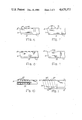
- FIG. 3 is a side elevation view of the insert shown in FIG. 2;
- FIG. 4 is a front view of the insert shown in FIG. 2;
- FIG. 5 is a section view of the insert shown in FIG. 4 taken along the line V--V;
- FIG. 6 is a side elevation view of an insert, as shown in FIG. 1, ground to provide a positive rake angle;
- FIG. 7 is a side elevation of an insert, as shown in FIG. 1, ground to provide a negative rake angle
- FIG. 8 is a side elevation view of an insert with grooves which will provide a negative rake angle over their width
- FIG. 9 is a side elevation view of an insert with grooves which will provide a positive rake angle over their width
- FIG. 10 is a top view of a cutoff insert wherein the top of the tip portion is higher than the top of the shank portion;
- FIG. 11 is a side view of the insert shown in FIG. 10;
- FIG. 12 is a top view of a cutoff insert wherein the cutting edge is formed on a radius
- FIG. 13 is a side view of the insert shown in FIG. 12;
- FIG. 14 is a plan view of a turning insert according to the present invention.
- FIG. 15 is a view of the insert of FIG. 14 along the line XV--XV;
- FIG. 16 is a plan view of another embodiment of a turning insert according to the invention.
- FIG. 17 is a view of the insert of FIG. 16 along the line XVII--XVII;
- FIG. 18 is a side view of a double ended insert.
- FIG. 19 is a front view of the insert shown in FIG. 18.
- Insert 10 constructed according to the teaching of the present invention.
- Insert 10 includes a shank or body portion 11 and a tip portion 12.
- the shank 11 and tip 12 are arranged coextensively to define an overall insert 10 of an elongated configuration.
- the shank 11 includes a top surface 20, opposed side surfaces 21 and 22, and a truncated V-shaped bottom surface 23, with the arrangement of these parts being similar to the arrangement shown in connection with Novkov, U.S. Pat. No. 2,964,833 whose teachings are herein incorporated by reference.
- Carbide tip 12 includes a transversely extending cutting edge 31 that is defined by the top of a forward face 32.
- Tip 12 includes a V-shaped bottom surface 35 and opposed side walls 36 and 37.
- the side walls 36 and 37 are preferably ground so as to provide the requisite degree of side and back clearance in the manner well known in the prior art.
- Tip 12 is fused in a known manner to the forward end of the shank 11 by brazing or other known metal joining techniques.
- Chamfers 40 and 41 are provided at the joint of juncture between the top surface 64 and the opposed side surfaces 36 and 37. The effect and purpose of the chamfers 40 and 41 is fully described in Stein U.S. Pat. No. 3,654,681 whose teachings are herein incorporated by reference.
- Tip 12 includes a longitudinal groove or channel 50 extending rearward from cutting edge 31.
- a curved shelf shaped rake portion 52 is provided extending rearward and upward from cutting edge 31 to a top surface 64.
- Longitudinal channel 50 extends through the cutting edge 31 and the shaped rake portion 52.
- Channel 50 may extend through the entire length of tip 12, but need not do so.
- longitudinal channel 50 acts to narrow a chip while the curved shelf portion 52 curls the chip to the point of breaking into clockspring or figure-nine shapes which are well known in this art.
- Dimensions of the channel 50 and shaped rake portion 52, and radii on the rear of the shaped rake portion 52, can all be varied to provide good chip control over a wide range of speed and feed conditions. In use, the illustrated chip controlling geometry has provided good chip control.
- a succession of transverse grooves 62 are provided across cutting tip 12.
- Grooves 62 are not as deep as the longitudinal channel 50 and are preferably perpendicular to and spaced along the length of tip 12. After a period of metal cutting as the cutting edge 31 becomes worn the tip 12 can be reground back to the next successive groove 62 to provide a new cutting edge 31 having associated therewith a shaped chip controlling surface which is very similar or identical to the chip controlling shape with the original cutting edge.
- Tip 12 narrows slightly as it extends rearward. Thus, each new ground cutting edge will be slightly narrower than the preceding cutting edge.
- the blade For high speed steel cut off blades, the blade need not be narrowed or be tapered as it extends rearward from the cutting edge. If these parallel blades are formed with a regrindable chip control geometry, as disclosed, the cutting edge will remain the same width even after being reground. This characteristic of no change in width after regrind would be beneficial on multiple spindle automatic machines where part length is determined by the location of the cutoff tool and the width of the cutting edge must remain the same.
- the tip can be reground three times.
- a new cutting edge 31 is defined and the portion of groove 62 remaining forms a new surface similar to 52 and provides chip control as explained above.
- a groove 62 width of 0.060 inches (1.5 mm) and depth of 0.012 inches (0.3 mm) and channel 50 width of 0.075 inches (1.9 mm) and depth of 0.020 inches (0.51 mm) have been found to work well.
- dashed lines 60 indicate the lines to which tip 12 is ground to provide new cutting edges having associated substantially identical chip controlling surfaces.
- tip 12 can be ground back either a little to the right or left of line 60, as shown in FIG. 3, to provide a cutting edge with a different rake angle.
- lines 60 can be physically marked on cutting tip 12 by a known method such as laser etching, electroetching, grinding, or the like. If lines are physically formed on tip 12 this could greatly facilitate regrinding.
- the insert shown in FIG. 3 has a neutral rake angle, and if it is ground back to line 60 the new cutting edge will also have a neutral rake angle. If, however, tip 12 is ground back to provide a cutting edge 31, as shown in FIG.
- groove 62 is shown with a semi-circle configuration, numerous other configurations can be provided.
- the front of the cross groove can drop sharply, then slant up to the top 64 of insert 10. This construction would provide a groove having a negative rake over most of its width.
- the cross groove could slope downward from the top 64 and blend into a rear wall which curves up to the top 64. This construction would provide a groove having a positive rake over its width.
- various other groove shapes can be provided, and also the groove shapes provided on a single insert can be individually different.
- the tip 12 can be coated with a desired coating such as titanium nitride, titanium carbide, or aluminum oxide.
- the desired coating is preferably applied after the desired shapes are formed in the top of tip 12. Thus, after each regrind each new chip controlling surface will still have associated therewith a coated rake face.
- FIGS. 10 and 11 shown an embodiment of cutoff insert 10 wherein the top of tip 12 is higher than the top of shank 11.
- FIGS. 12 and 13 shown an embodiment of cutoff insert 10 wherein the front cutting edge is formed along a selected radius, R.
- FIGS. 18 and 19 show a double ended cutoff insert 110.
- cutoff insert 10 provides good chip control over a wide range of speeds, feeds, and materials. Cutoff insert 10 is also regrindable a number of times, depending on the number of transverse grooves 62 provided in tip 12.
- the teaching of this invention while generally explained in terms of a cutoff insert 10 are not limited thereto, but are applicable to a wide range of cutting tools and inserts. When the terms insert or tool are used in the specification or claims, it is intended that they be construed to mean both inserts and tools.
- FIGS. 14 and 15 and FIGS. 16 and 17 show turning inserts 120 and 130 respectively, constructed according to the present invention.
Abstract
Description
Claims (12)
Priority Applications (1)
| Application Number | Priority Date | Filing Date | Title |
|---|---|---|---|
| US06/731,325 US4629372A (en) | 1981-02-02 | 1985-05-03 | Chip-controlling insert |
Applications Claiming Priority (2)
| Application Number | Priority Date | Filing Date | Title |
|---|---|---|---|
| US23022981A | 1981-02-02 | 1981-02-02 | |
| US06/731,325 US4629372A (en) | 1981-02-02 | 1985-05-03 | Chip-controlling insert |
Related Parent Applications (1)
| Application Number | Title | Priority Date | Filing Date |
|---|---|---|---|
| US06503458 Continuation | 1983-06-13 |
Publications (1)
| Publication Number | Publication Date |
|---|---|
| US4629372A true US4629372A (en) | 1986-12-16 |
Family
ID=26924036
Family Applications (1)
| Application Number | Title | Priority Date | Filing Date |
|---|---|---|---|
| US06/731,325 Expired - Lifetime US4629372A (en) | 1981-02-02 | 1985-05-03 | Chip-controlling insert |
Country Status (1)
| Country | Link |
|---|---|
| US (1) | US4629372A (en) |
Cited By (28)
| Publication number | Priority date | Publication date | Assignee | Title |
|---|---|---|---|---|
| US4832541A (en) * | 1987-05-20 | 1989-05-23 | Sumitomo Electric Industries, Ltd. | Grooving insert |
| US4969779A (en) * | 1989-02-10 | 1990-11-13 | Iscar Ltd. | Cutting insert |
| US4993893A (en) * | 1990-01-08 | 1991-02-19 | Kennametal Inc. | Cutting insert with chip control |
| US5085541A (en) * | 1990-09-13 | 1992-02-04 | Manchester Tool Company | Metal-cutting insert |
| DE4118065A1 (en) * | 1991-06-01 | 1992-12-03 | Krupp Widia Gmbh | UNIQUE OR ROUND CUTTING INSERT |
| US5423639A (en) * | 1992-10-28 | 1995-06-13 | Sandvik Ab | Cutting insert for chipforming machining of workpieces |
| US5626189A (en) * | 1995-09-22 | 1997-05-06 | Weatherford U.S., Inc. | Wellbore milling tools and inserts |
| WO1997046346A1 (en) * | 1996-06-06 | 1997-12-11 | Sandvik Aktiebolag (Publ) | Cutting insert for grooving operations |
| US5810079A (en) | 1986-01-06 | 1998-09-22 | Baker Hughes Incorporated | Downhole milling tool |
| US5908071A (en) * | 1995-09-22 | 1999-06-01 | Weatherford/Lamb, Inc. | Wellbore mills and inserts |
| US5984005A (en) * | 1995-09-22 | 1999-11-16 | Weatherford/Lamb, Inc. | Wellbore milling inserts and mills |
| US6170576B1 (en) | 1995-09-22 | 2001-01-09 | Weatherford/Lamb, Inc. | Mills for wellbore operations |
| US6217264B1 (en) * | 1998-05-30 | 2001-04-17 | Korloy, Inc. | Cutting insert having an improved chip breaker |
| WO2003070419A1 (en) * | 2002-02-19 | 2003-08-28 | Manchester Tool Company | Cutting insert |
| WO2004035257A2 (en) | 2002-10-18 | 2004-04-29 | Manchester Tool Company | Tool holder and metal cutting insert with chip breaking surfaces |
| US20040101374A1 (en) * | 2002-06-25 | 2004-05-27 | Seco Tools Ab | Cutting insert for chip removing machining |
| US6758638B1 (en) * | 1999-09-01 | 2004-07-06 | Mircona Ab | Method and holding device for a cutting tool |
| US6843620B2 (en) * | 2000-12-28 | 2005-01-18 | Ngk Spark Plug Co., Ltd. | Cutting tool and indexiable insert therefor |
| US20050123367A1 (en) * | 2003-12-04 | 2005-06-09 | Iscar, Ltd. | Cutting insert for grooving operations |
| US20070065240A1 (en) * | 2004-02-11 | 2007-03-22 | Ceratizit Austria Gesellschaft M.B.H. | Cutting insert and tool and wrench for using the same |
| US20080031698A1 (en) * | 2004-07-22 | 2008-02-07 | Boehlerit Gmbh & Co. Kg. | Cutting Insert Provided With Structured Surfaces |
| US20100067998A1 (en) * | 2008-09-18 | 2010-03-18 | Fujitsu Limited | Processing apparatus and processing method |
| US20100183390A1 (en) * | 2009-01-20 | 2010-07-22 | Mr Ulf Heule | Cutting Knife For Chip-Removing Cutting Tools With Breaking Notch |
| US20130309028A1 (en) * | 2012-05-15 | 2013-11-21 | Iscar, Ltd. | Cutting Insert with Chip-Control Arrangement Having Recess Depths and Projection Heights Which Increase with Distance from Cutting Edge |
| US20190262908A1 (en) * | 2018-02-28 | 2019-08-29 | Iscar Ltd. | Cutting insert having land with spaced apart upwardly bulging land portions and non-rotary cutting tool provided therewith |
| US10814399B2 (en) * | 2014-11-24 | 2020-10-27 | Sandvik Intellectual Property Ab | Method of grinding a parting/grooving insert and a parting/grooving insert |
| US20210205895A1 (en) * | 2018-05-24 | 2021-07-08 | No Screw Ltd. | Tool and cutting insert for internal cooling, and methos of manufacturing thereof |
| US20220274185A1 (en) * | 2021-02-26 | 2022-09-01 | Tungaloy Corporation | Cutting insert |
Citations (25)
| Publication number | Priority date | Publication date | Assignee | Title |
|---|---|---|---|---|
| DE1070898B (en) * | 1958-04-09 | |||
| US1299125A (en) * | 1918-02-11 | 1919-04-01 | Pratt & Whitney Co | Cutting-tool. |
| DE426244C (en) * | 1925-03-04 | 1926-03-05 | Ernst Porscheng | Cutting lathe or planing tool |
| DE494265C (en) * | 1928-05-13 | 1930-03-20 | Alexander Ignatieff | Cutting tool with multiple cutting layers |
| US2164303A (en) * | 1937-12-08 | 1939-07-04 | Alfred J Berg | Tool for cutting or turning |
| US2176265A (en) * | 1938-01-28 | 1939-10-17 | John M Luers | Tool |
| CA397745A (en) * | 1941-07-08 | M. Luers John | Parting tool | |
| US2256847A (en) * | 1936-12-15 | 1941-09-23 | Eibes Kerb Konus Gmbh | Tool |
| FR879235A (en) * | 1940-08-16 | 1943-02-17 | Tool, such as a lathe tool or the like, with a hard metal cutter | |
| US2424473A (en) * | 1945-11-08 | 1947-07-22 | John Milton Luers Patents Inc | Cutting-off blade |
| US2641048A (en) * | 1951-04-14 | 1953-06-09 | Vreeland Whitney | Cutting tool |
| US2688791A (en) * | 1953-05-28 | 1954-09-14 | Luers | Cutting-off blade |
| US2891300A (en) * | 1954-01-14 | 1959-06-23 | Evelyn De Mauro | Cut-off tool |
| US3175276A (en) * | 1963-02-27 | 1965-03-30 | Caterpillar Tractor Co | Rotary mill |
| US3364544A (en) * | 1967-03-13 | 1968-01-23 | Pipe Machinery Company | Cut-off tool and chip reforming breaker |
| US3654681A (en) * | 1970-04-22 | 1972-04-11 | Warner Swasey Co | Cutoff tool having improved chip relieving surface |
| US3815191A (en) * | 1971-07-07 | 1974-06-11 | Sandvik Ab | Chip-forming cutting tool |
| US3909896A (en) * | 1974-05-02 | 1975-10-07 | William Krozal | Cutting tool for parting or grooving a workpiece |
| US3947937A (en) * | 1973-11-16 | 1976-04-06 | Karl Hertel | Control groove in cutting elements for metal working tools |
| US3973308A (en) * | 1974-04-24 | 1976-08-10 | Sandvik Aktiebolag | Cutting tool |
| CA1010640A (en) * | 1975-07-30 | 1977-05-24 | Karl Hertel | Cutting element for cutting metals |
| JPS5325982A (en) * | 1976-08-21 | 1978-03-10 | Mitsubishi Metal Corp | Throw-away tip |
| JPS5438755A (en) * | 1977-09-01 | 1979-03-23 | Mitsubishi Electric Corp | Spot knocking method for cathode-ray tube |
| US4337562A (en) * | 1980-04-07 | 1982-07-06 | Rockford Carbide Corporation | Method of restoring an indexable cutting insert for reuse |
| USD275760S (en) | 1982-09-30 | 1984-10-02 | The Warner & Swasey Company | Cutting tool insert |
-
1985
- 1985-05-03 US US06/731,325 patent/US4629372A/en not_active Expired - Lifetime
Patent Citations (25)
| Publication number | Priority date | Publication date | Assignee | Title |
|---|---|---|---|---|
| CA397745A (en) * | 1941-07-08 | M. Luers John | Parting tool | |
| US1299125A (en) * | 1918-02-11 | 1919-04-01 | Pratt & Whitney Co | Cutting-tool. |
| DE426244C (en) * | 1925-03-04 | 1926-03-05 | Ernst Porscheng | Cutting lathe or planing tool |
| DE494265C (en) * | 1928-05-13 | 1930-03-20 | Alexander Ignatieff | Cutting tool with multiple cutting layers |
| US2256847A (en) * | 1936-12-15 | 1941-09-23 | Eibes Kerb Konus Gmbh | Tool |
| US2164303A (en) * | 1937-12-08 | 1939-07-04 | Alfred J Berg | Tool for cutting or turning |
| US2176265A (en) * | 1938-01-28 | 1939-10-17 | John M Luers | Tool |
| FR879235A (en) * | 1940-08-16 | 1943-02-17 | Tool, such as a lathe tool or the like, with a hard metal cutter | |
| US2424473A (en) * | 1945-11-08 | 1947-07-22 | John Milton Luers Patents Inc | Cutting-off blade |
| US2641048A (en) * | 1951-04-14 | 1953-06-09 | Vreeland Whitney | Cutting tool |
| US2688791A (en) * | 1953-05-28 | 1954-09-14 | Luers | Cutting-off blade |
| US2891300A (en) * | 1954-01-14 | 1959-06-23 | Evelyn De Mauro | Cut-off tool |
| DE1070898B (en) * | 1958-04-09 | |||
| US3175276A (en) * | 1963-02-27 | 1965-03-30 | Caterpillar Tractor Co | Rotary mill |
| US3364544A (en) * | 1967-03-13 | 1968-01-23 | Pipe Machinery Company | Cut-off tool and chip reforming breaker |
| US3654681A (en) * | 1970-04-22 | 1972-04-11 | Warner Swasey Co | Cutoff tool having improved chip relieving surface |
| US3815191A (en) * | 1971-07-07 | 1974-06-11 | Sandvik Ab | Chip-forming cutting tool |
| US3947937A (en) * | 1973-11-16 | 1976-04-06 | Karl Hertel | Control groove in cutting elements for metal working tools |
| US3973308A (en) * | 1974-04-24 | 1976-08-10 | Sandvik Aktiebolag | Cutting tool |
| US3909896A (en) * | 1974-05-02 | 1975-10-07 | William Krozal | Cutting tool for parting or grooving a workpiece |
| CA1010640A (en) * | 1975-07-30 | 1977-05-24 | Karl Hertel | Cutting element for cutting metals |
| JPS5325982A (en) * | 1976-08-21 | 1978-03-10 | Mitsubishi Metal Corp | Throw-away tip |
| JPS5438755A (en) * | 1977-09-01 | 1979-03-23 | Mitsubishi Electric Corp | Spot knocking method for cathode-ray tube |
| US4337562A (en) * | 1980-04-07 | 1982-07-06 | Rockford Carbide Corporation | Method of restoring an indexable cutting insert for reuse |
| USD275760S (en) | 1982-09-30 | 1984-10-02 | The Warner & Swasey Company | Cutting tool insert |
Non-Patent Citations (4)
| Title |
|---|
| Manchester carbide cutoff tools, Form No. 329J, May, 1981. * |
| Manchester carbide tooling systems, Form No. 319J. * |
| Manchester face grooving and trepanning tools, Form No. 330F, Nov. 1981. * |
| Manchester stocksaver carbide inserts, Form No. 326G, May, 1981. * |
Cited By (46)
| Publication number | Priority date | Publication date | Assignee | Title |
|---|---|---|---|---|
| US5899268A (en) | 1986-01-06 | 1999-05-04 | Baker Hughes Incorporated | Downhole milling tool |
| US5810079A (en) | 1986-01-06 | 1998-09-22 | Baker Hughes Incorporated | Downhole milling tool |
| US4832541A (en) * | 1987-05-20 | 1989-05-23 | Sumitomo Electric Industries, Ltd. | Grooving insert |
| US4969779A (en) * | 1989-02-10 | 1990-11-13 | Iscar Ltd. | Cutting insert |
| US4993893A (en) * | 1990-01-08 | 1991-02-19 | Kennametal Inc. | Cutting insert with chip control |
| EP0510109A1 (en) * | 1990-01-08 | 1992-10-28 | Kennametal Inc | Cutting insert with chip control. |
| EP0510109B1 (en) * | 1990-01-08 | 1996-01-24 | Kennametal Inc. | Cutting insert with chip control |
| US5085541A (en) * | 1990-09-13 | 1992-02-04 | Manchester Tool Company | Metal-cutting insert |
| DE4118065A1 (en) * | 1991-06-01 | 1992-12-03 | Krupp Widia Gmbh | UNIQUE OR ROUND CUTTING INSERT |
| US5525016A (en) * | 1991-06-01 | 1996-06-11 | Widia Gmbh | Cutting insert with grouped chip-forming ribs arranged symmetrically and having tapering cross sections |
| US5423639A (en) * | 1992-10-28 | 1995-06-13 | Sandvik Ab | Cutting insert for chipforming machining of workpieces |
| US5626189A (en) * | 1995-09-22 | 1997-05-06 | Weatherford U.S., Inc. | Wellbore milling tools and inserts |
| US6170576B1 (en) | 1995-09-22 | 2001-01-09 | Weatherford/Lamb, Inc. | Mills for wellbore operations |
| US5908071A (en) * | 1995-09-22 | 1999-06-01 | Weatherford/Lamb, Inc. | Wellbore mills and inserts |
| US5984005A (en) * | 1995-09-22 | 1999-11-16 | Weatherford/Lamb, Inc. | Wellbore milling inserts and mills |
| WO1997046346A1 (en) * | 1996-06-06 | 1997-12-11 | Sandvik Aktiebolag (Publ) | Cutting insert for grooving operations |
| US6135678A (en) * | 1996-06-06 | 2000-10-24 | Sandvik Aktiebolag | Cutting insert for grooving operations |
| CN1084238C (en) * | 1996-06-06 | 2002-05-08 | 桑德维克公司 | Cutting insert for grooving operations |
| US6217264B1 (en) * | 1998-05-30 | 2001-04-17 | Korloy, Inc. | Cutting insert having an improved chip breaker |
| US6758638B1 (en) * | 1999-09-01 | 2004-07-06 | Mircona Ab | Method and holding device for a cutting tool |
| US6843620B2 (en) * | 2000-12-28 | 2005-01-18 | Ngk Spark Plug Co., Ltd. | Cutting tool and indexiable insert therefor |
| US6742971B2 (en) | 2002-02-19 | 2004-06-01 | Manchester Tool Company | Cutting insert |
| WO2003070419A1 (en) * | 2002-02-19 | 2003-08-28 | Manchester Tool Company | Cutting insert |
| US6799925B2 (en) * | 2002-06-25 | 2004-10-05 | Seco Tools Ab | Cutting insert for chip removing machining |
| US20040101374A1 (en) * | 2002-06-25 | 2004-05-27 | Seco Tools Ab | Cutting insert for chip removing machining |
| US7883300B1 (en) * | 2002-10-18 | 2011-02-08 | Kennametal Inc. | Tool holder and metal cutting insert with chip breaking surfaces |
| WO2004035257A2 (en) | 2002-10-18 | 2004-04-29 | Manchester Tool Company | Tool holder and metal cutting insert with chip breaking surfaces |
| EP1558431B1 (en) | 2002-10-18 | 2017-05-03 | Kennametal Inc. | Metal cutting insert with chip breaking surfaces |
| US20050123367A1 (en) * | 2003-12-04 | 2005-06-09 | Iscar, Ltd. | Cutting insert for grooving operations |
| US7320564B2 (en) * | 2003-12-04 | 2008-01-22 | Iscar Ltd. | Cutting insert for grooving operations |
| US20070065240A1 (en) * | 2004-02-11 | 2007-03-22 | Ceratizit Austria Gesellschaft M.B.H. | Cutting insert and tool and wrench for using the same |
| US7341433B2 (en) | 2004-02-11 | 2008-03-11 | Ceratizit Austria Gesellschaft M.B.H. | Cutting insert and tool and wrench for using the same |
| US20080031698A1 (en) * | 2004-07-22 | 2008-02-07 | Boehlerit Gmbh & Co. Kg. | Cutting Insert Provided With Structured Surfaces |
| US8534967B2 (en) * | 2008-09-18 | 2013-09-17 | Fujitsu Limited | Processing apparatus and processing method |
| US20100067998A1 (en) * | 2008-09-18 | 2010-03-18 | Fujitsu Limited | Processing apparatus and processing method |
| US20100183390A1 (en) * | 2009-01-20 | 2010-07-22 | Mr Ulf Heule | Cutting Knife For Chip-Removing Cutting Tools With Breaking Notch |
| US8708614B2 (en) * | 2009-01-20 | 2014-04-29 | Heule, Ulf | Cutting knife for chip-removing cutting tools with breaking notch |
| US20130309028A1 (en) * | 2012-05-15 | 2013-11-21 | Iscar, Ltd. | Cutting Insert with Chip-Control Arrangement Having Recess Depths and Projection Heights Which Increase with Distance from Cutting Edge |
| US8939684B2 (en) * | 2012-05-15 | 2015-01-27 | Iscar, Ltd. | Cutting insert with chip-control arrangement having recess depths and projection heights which increase with distance from cutting edge |
| US10814399B2 (en) * | 2014-11-24 | 2020-10-27 | Sandvik Intellectual Property Ab | Method of grinding a parting/grooving insert and a parting/grooving insert |
| US11890683B2 (en) * | 2014-11-24 | 2024-02-06 | Sandvik Intellectual Property Ab | Method of grinding a parting/grooving insert and a parting/grooving insert |
| US20190262908A1 (en) * | 2018-02-28 | 2019-08-29 | Iscar Ltd. | Cutting insert having land with spaced apart upwardly bulging land portions and non-rotary cutting tool provided therewith |
| US10987740B2 (en) * | 2018-02-28 | 2021-04-27 | Iscar Ltd. | Cutting insert having land with spaced apart upwardly bulging land portions and non-rotary cutting tool provided therewith |
| US20210205895A1 (en) * | 2018-05-24 | 2021-07-08 | No Screw Ltd. | Tool and cutting insert for internal cooling, and methos of manufacturing thereof |
| US20220274185A1 (en) * | 2021-02-26 | 2022-09-01 | Tungaloy Corporation | Cutting insert |
| US11772166B2 (en) * | 2021-02-26 | 2023-10-03 | Tungaloy Corporation | Cutting insert |
Similar Documents
| Publication | Publication Date | Title |
|---|---|---|
| US4629372A (en) | Chip-controlling insert | |
| JP2744574B2 (en) | Polygon insert for turning and grooving | |
| EP0489701B1 (en) | Cutting insert and cutting tool for a peeling operation | |
| US4659264A (en) | Drill and indexable carbide insert therefor | |
| US4531864A (en) | Cutting insert | |
| US4681486A (en) | Triangular cutting tool insert having cutting edges with recesses | |
| US4832541A (en) | Grooving insert | |
| JP4489874B2 (en) | Cutting tips for machining to form chips | |
| US5085542A (en) | Indexable cutting insert | |
| EP0310239B1 (en) | A cutting insert | |
| CA2152706C (en) | Cutting insert | |
| US5456557A (en) | Cutting insert | |
| EP0577011A1 (en) | Throw away insert and face milling cutter | |
| US5709509A (en) | Cutting insert | |
| EP0821627B1 (en) | Cutting insert with chip control | |
| JP2002516185A (en) | Cutting insert for grooving | |
| AU2004216407B2 (en) | Cutting insert for grooving operations | |
| US4834592A (en) | Cutting insert with chip control | |
| EP0159747B1 (en) | Cutoff insert | |
| JPH0819905A (en) | Insert for cutting | |
| US4854785A (en) | Scalloped threader cutting insert | |
| EP1689546B1 (en) | Cutting insert for grooving operations | |
| US5549424A (en) | Indexable threading and turning insert with pressed-in chip breakers | |
| USRE37595E1 (en) | Cutting insert for cutting and grooving tools | |
| TWI773866B (en) | Cutting insert having land with spaced apart upwardly bulging land portions and non-rotary cutting tool provided therewith |
Legal Events
| Date | Code | Title | Description |
|---|---|---|---|
| STCF | Information on status: patent grant |
Free format text: PATENTED CASE |
|
| CC | Certificate of correction | ||
| FEPP | Fee payment procedure |
Free format text: PAYOR NUMBER ASSIGNED (ORIGINAL EVENT CODE: ASPN); ENTITY STATUS OF PATENT OWNER: LARGE ENTITY |
|
| FEPP | Fee payment procedure |
Free format text: PAT HLDR NO LONGER CLAIMS SMALL ENT STAT AS SMALL BUSINESS (ORIGINAL EVENT CODE: LSM2); ENTITY STATUS OF PATENT OWNER: LARGE ENTITY |
|
| FPAY | Fee payment |
Year of fee payment: 4 |
|
| AS | Assignment |
Owner name: CITICORP USA, INC. Free format text: SECURITY INTEREST;ASSIGNOR:WARNER & SWASEY COMPANY, THE, A CORP. OF MI;REEL/FRAME:005900/0719 Effective date: 19911031 |
|
| FPAY | Fee payment |
Year of fee payment: 8 |
|
| FPAY | Fee payment |
Year of fee payment: 12 |
|
| AS | Assignment |
Owner name: WARNER & SWASEY COMPANY, THE, WISCONSIN Free format text: RELEASE OF SECURITY INTEREST;ASSIGNOR:CITICORP USA, INC.;REEL/FRAME:013986/0361 Effective date: 19921231 |