US4620773A - Projection lens for projection television - Google Patents
Projection lens for projection television Download PDFInfo
- Publication number
- US4620773A US4620773A US06/494,447 US49444783A US4620773A US 4620773 A US4620773 A US 4620773A US 49444783 A US49444783 A US 49444783A US 4620773 A US4620773 A US 4620773A
- Authority
- US
- United States
- Prior art keywords
- lens
- sup
- sub
- cathode
- lenses
- Prior art date
- Legal status (The legal status is an assumption and is not a legal conclusion. Google has not performed a legal analysis and makes no representation as to the accuracy of the status listed.)
- Expired - Fee Related
Links
Images


Classifications
-
- G—PHYSICS
- G02—OPTICS
- G02B—OPTICAL ELEMENTS, SYSTEMS OR APPARATUS
- G02B9/00—Optical objectives characterised both by the number of the components and their arrangements according to their sign, i.e. + or -
- G02B9/34—Optical objectives characterised both by the number of the components and their arrangements according to their sign, i.e. + or - having four components only
-
- G—PHYSICS
- G02—OPTICS
- G02B—OPTICAL ELEMENTS, SYSTEMS OR APPARATUS
- G02B13/00—Optical objectives specially designed for the purposes specified below
- G02B13/16—Optical objectives specially designed for the purposes specified below for use in conjunction with image converters or intensifiers, or for use with projectors, e.g. objectives for projection TV
-
- G—PHYSICS
- G02—OPTICS
- G02B—OPTICAL ELEMENTS, SYSTEMS OR APPARATUS
- G02B13/00—Optical objectives specially designed for the purposes specified below
- G02B13/18—Optical objectives specially designed for the purposes specified below with lenses having one or more non-spherical faces, e.g. for reducing geometrical aberration
-
- H—ELECTRICITY
- H04—ELECTRIC COMMUNICATION TECHNIQUE
- H04N—PICTORIAL COMMUNICATION, e.g. TELEVISION
- H04N5/00—Details of television systems
- H04N5/74—Projection arrangements for image reproduction, e.g. using eidophor
- H04N5/7408—Direct viewing projectors, e.g. an image displayed on a video CRT or LCD display being projected on a screen
Definitions
- This invention relates to a projection lens used in a so-called projection television apparatus in which an enlargement of an image appearing on a cathode-ray tube is projected on a large screen.
- the factors governing the quality of an image projected on a projection screen in such a projection television apparatus include the cathode-ray tube, projection lens and screen, and the present invention contemplates to improve the image quality by improving the structure of the projection lens. It is the recent tendency to change the material of the projection lens of the kind above described from the glass to a plastic material and provide aspherical lens surfaces so as to improve the brightness and resolution even with a small number of component lenses.
- Such a proposal is made in, for example, U.S. Pat. No. 4,300,817.
- the U.S. patent discloses a projection lens of three lens structure attaining an f-number of 1.0 thereby providing a very high brightness when compared with the past one.
- FIG. 1 shows schematically the structure of a projection television apparatus using such a projection lens.
- the projection television apparatus shown in FIG. 1 includes a projection lens of three lens structure, and the reference numeral 1 designates a casing; 2, a cathode-ray tube; 3, a projection screen; 4, 5, 6, mirrors; 7, a having a concave surface lens; and 8, 9, having convex surfaces lenses.
- an image appearing on the cathode-ray tube 2 disposed in the casing 1 is magnified by the projection lens composed of the lens 7 and lenses 8, 9, and the magnified image is reflected by the mirrors 5, 6 to be projected and displayed on the projection screen 3 fixed to the casing 1.
- the projection lens is composed of the lens 7 and lenses 8 and 9, a bright magnified image can be displayed on the projection screen 3. Further, since the optical path from the cathode-ray tube 2 to the projection screen 3 is bent by the mirrors 5 and 6, and, also, since the mirror 4 interposed between the lenses 8 and 9 having convex surfaces of the projection lens acts to bend the optical path, the projection television apparatus can be made compact and small in overall size.
- the lenses 7, 8 and 9 composing such a projection lens are configured to have predetermined spherical and aspherical surfaces to eliminate aberrations thereby improving the resolution, the resolution of the illustrated projection lens is not still fully sufficient or satisfactory. This is because a relatively large aberration occurs in the marginal zone of the image plane.
- the contrast is another important item required for the image quality in such a projection television apparatus.
- the contrast is affected greatly by the stray light resulting from reflection by the lens surfaces, lens barrels, etc.
- the prior art projection lens disclosed in the cited U.S. patent has been defective in that the contrast is greatly degraded by the reflection of light from the concave lens surfaces.
- the present invention which attains the above object is featured by the fact that a first lens having a concave surface, a second lens which is a convex meniscus lens having a concave surface opposite the concave surface of the concave lens, a third lens having a strongest refracting power and at least one convex surface, and a fourth lens having a relatively weak power and at least one convex surface are arranged in the above order from the side of a cathode-ray tube, and a space is provided between the third and fourth lenses so that a mirror for bending the optical path can be disposed in the space.
- FIG. 1 shows schematically the structure of one form of a prior art projection television apparatus.
- FIG. 2 shows schematically the stucture of an embodiment of the projection lens according to the present invention.
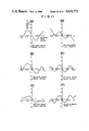
- FIGS. 3(A) to 3(F) and FIGS. 4(A) to 4(E) are graphs showing lateral aberrations in the saggital and meridional directions respectively when the projection lens shown in FIG. 2 is used to provide a magnification of 8.7.
- FIG. 5 shows schematically the structure of one form of a projection television apparatus which includes the projection lens shown in FIG. 2.
- FIGS. 6(A) to 6(C) and FIGS. 7(A) to 7(C) are graphs showing lateral aberrations in the meridional and saggital directions respectively when the projection lens shown in FIG. 2 is used to provide a magnification of 9.37.
- FIG. 8 shows schematically the structure of another embodiment of the projection lens according to the present invention.
- FIGS. 9(A) to 9(L) are graphs showing the aberration characteristics of the embodiment shown in FIG. 8.
- FIG. 10 shows schematically the structure of still another embodiment of the projection lens according to the present invention.
- FIGS. 11(A) to 11(L) are graphs showing the aberration characteristics of the embodiment shown in FIG. 10.
- FIG. 2 shows schematically the structure of an embodiment of the projection lens according to the present invention.
- the reference numeral 10 designates a convex meniscus lens, and like reference numerals are used to designate like or equivalent parts appearing in FIG. 1.
- a concave lens 7 which is substantially plano at the surface opposite to a cathode-ray tube 2 and concave at the other surface
- a convex meniscus lens 10 which is concave at the surface opposite to the concave lens 7 and convex at the other surface
- a first convex lens 8 which is bi-convex and has a strongest positive refracting power
- a second convex lens 9 which is plano at the surface opposite to the convex lens 8 and convex at the other surface and has a relatively weak power, are arranged in the above order from the side of the cathode-ray tube 2 to compose a projection lens.
- All of these lenses 7 to 10 are made of an acrylic resin material and have spherical or aspherical surfaces.
- the concave lens 7 acts to correct the curvature of field thereby flattening the field.
- the surface (which will be referred to hereinafter as a surface S 1 ) of the concave lens 7 opposite to the cathode-ray tube 2 is substantially plano, while the other surface (which will be referred to hereinafter as a surface S 2 ) is in the form of a concave aspherical surface.
- the combination of the convex meniscus lens 10 and the convex lens 8 acts to correct aberrations in the marginal zone of the image plane thereby improving the resolution.
- the concave surface (referred to hereinafter as a surface S 3 ) of the convex meniscus lens 10 opposite to the concave lens 7 and the surface (referred to hereinafter as a surface S 6 ) of the convex lens 8 on the side of the concave surface of the lens 7 are both aspherical.
- the other convex surface (referred to hereinafter as a surface S 4 ) of the convex meniscus lens 10 and the other surface (referred to hereinafter as a surface S 5 ) of the convex lens 8 are both spherical.
- the convex lens 9 acts to correct the spherical aberration.
- the surface (referred to hereinafter as a surface S 7 ) of the convex lens 9 opposite to the convex lens 8 is plano, while the other surface (referred to hereinafter as a surface S 8 ) is aspherical.
- Table 1 shows the radius of surface curvature, clear aperture, axial distance between surfaces and index of refraction of each of the lenses composing the projection lens shown in FIG. 2, and Table 2 shows the aspherical coefficients of the lens surfaces S 2 , S 3 , S 6 and S 8 .
- the f-number and focal distance of this projection lens are 0.95 and 117.4 mm respectively.
- the aspherical coefficients CC, AD, AE, AF and AG in Table 2 are those included in the following equation which represents the axial displacement Z at a semi-aperture distance r from the optical axis of the lens: ##EQU1## where C is the reciprocal of the radius of curvature at the optical axis.
- FIGS. 3(A) to 3(F) and FIGS. 4(A) to 4(E) are graphs showing aberrations when the projection lens shown in FIG. 2 is used to provide a magnification of 8.7. More precisely, FIGS. 3(A) to 3(F) are graphs showing lateral aberrations in the saggital direction when the object height is 63.5 mm, 50.4 mm, 38.1 mm, 25.4 mm, 12.7 mm and 0.0 mm respectively, while FIGS. 4(A) to 4(E) are graphs showing lateral aberrations in the meridional direction when the object height is 63.5 mm, 50.4 mm, 38.1 mm, 25.4 mm and 12.7 mm respectively.
- the lateral aberrations can be limited to within 3 mm, and the aberrations on the central axis are sufficiently corrected even in the marginal zones up to the f-number of 0.95. Therefore, a bright magnified image of high resolution can be displayed on the projection screen 3 shown in FIG. 2.
- the distance between the surface S 6 of the first convex lens 8 and the surface S 7 of the second convex lens 9 is 115 mm which is large enough to permit interposition of the mirror 4 between the convex lenses 8 and 9. Therefore, the optical path can be bent also by the mirror 4 so tht the overall size of the projection television apparatus can be made small.
- the distance TH between two lenses to permit interposition of a mirror therebetween is given by ##EQU2## where D 1 and D 2 are the clear apertures of the opposing surfaces of these lenses respectively.
- TH may be expressed as follows: ##EQU3##
- FIG. 5 shows schematically the structure of one form of a projection television apparatus which includes such a projection lens, and the same reference numerals are used to designate the same or equivalent parts appearing in FIGS. 1 and 2.
- the mirror 4 can be interposed between the convex lenses 8 and 9 and acts to bend the optical path together with the mirrors 5 and 6 so that the overall size of the projection television apparatus can be made small. Further, the marginal aberrations can be reduced by the combined action of the convex meniscus lens 10 and convex lens 8, and the aberrations can be corrected up to the f-number of 0.95 so that a bright magnified image of high resolution can be displayed on the projection screen 3.
- the values related to the lens surface S 6 are those measured when an aperture diaphragm is provided. Also, the symbols C 1 and C 2 designate the phosphor screen side surface and the other surface of the face plate respectively.
- FIGS. 6(A) to 6(C) and FIGS. 7(A) to 7(C) are graphs showing a berrations when the projection lens shown in FIG. 2 is used to provide a magnification of 9.37. More precisely, FIGS. 6(A) to 6(C) are graphs showing lateral aberrations in the meridional direction at the relative object height of various values respectively, while FIGS. 7(A) to 7(C) are graphs showing lateral aberrations in the saggital direction at the relative object height of various values respectively.
- the lateral aberrations can be limited to within 2 mm, and the aberrations on the central axis are sufficiently corrected even in the marginal zones up to the f-number of 0.95.
- the distance between the convex lenses 8 and 9 is 115 mm which is large enough to permit interposition of the mirror 4 therebetween in view of the expressions (1) and (2) described already. Since thus the optical path can be bent also by the mirror 4 so that the overall size of the projection television apparatus can be made small as shown in FIG. 5.
- FIG. 8 The embodiment shown in FIG. 8 is featured by the fact that a concave lens L 1 7 which is substantially plano at the surface S 1 opposite to a cathode-ray tube 1 and concave at the other surface S 2 , a convex meniscus lens L 2 8 which is concave at the surface S 3 opposite to the lens L 1 7 and convex at the other surface S 4 , another convex meniscus lens L 3 9 which is concave at the surface S 5 opposite to the lens L 2 8 and convex at the other surface S 6 , and a convex lens L 4 10 which is plano at the surface S 7 opposite to the lens L 3 9 and convex at the other surface S 8 and has a relatively weak power, are arranged in the above order from the side of the cathode-ray tube 1 to compose a projection lens of four lens structure, and the lens L 3 9 contributing most to the overall power is made of a glass material so as to minimize degradation of focussing due to the adverse effect of temperature.
- FIG. 8 is further featured by the fact that a transparent medium 11 having an index of refraction of 1.4 to 1.6 is filled in the space between the lens L 1 7 and the cathode-ray tube 1 to minimize reflection of light from the surfaces of the cathode-ray tube 1 and lens L 1 7 thereby improving the contrast.
- an image scanned by the electron beams on the phosphor screen of the cathode-ray tube 1 is magnified by the first lens L 1 7, second lens L 2 8, third lens L 3 9 and fourth lens L 4 10, and the magnified image is displayed on the projection screen 3 shown in FIG. 2.
- the third lens L 3 9 contributing most to the overall power is made of a glass material as described above, while the remaining first, second and fourth lenses are made of a plastic material such as an acrylic resin.
- the lens data of these lenses are shown in Tables 5 and 6.
- the aspherical coefficients CC, AD, AE, AF and AG in Table 6 are those included in the following equation which represents the axial displacement Z at a semi-aperture distance r from the optical axis of the lens: ##EQU4## where C is the reciprocal of the radius of curvature at the optical axis.
- FIGS. 9(A) to 9(L) are graphs showing aberrations on the projection screen 3 when the projection lens shown in FIG. 8 is used to magnify a phosphor image of 4.8 inches on the phosphor screen of the cathode-ray tube 1 with a magnification of 9.67 to display a magnified image of 45 inches on the projection screen 3. More precisely, FIGS. 9(A) to 9(F) are graphs showing lateral aberrations in the saggital direction, in each of which the vertical axis represents the aberration and the horizontal axis represents the relative pupil height. FIGS.
- 9(G) to 9(L) are graphs showing lateral aberrations in the meridional direction, in each of which the vertical and horizontal axes represent the same amounts as those in FIG. 9(A) respectively. It will be apparent from these graphs that the aberrations on the central axis are sufficiently corrected even in the marginal zones up to the f-number of 0.9. Further, owing to the fact that the lens L 3 9 contributing most to the overall power among the four lens groups is made of glass, the projection lens is not susceptible to the adverse effect of temperature. Actually, in the case of the projection lens of the present invention shown in FIG. 8, the rate of defocusing of a projected image due to a temperature variation can be reduced to about one-half the prior art rate. In the lens system of the present invention, the both surfaces of the lens L 2 are made aspherical to maintain least possible aberrations.
- BK 7 is used as the material of the glass lens L 3 .
- the dispersion of such a glass lens is less by 10 to 20% than that of an acrylic lens, and, therefore, the chromatic aberration can also be reduced by 10 to 20%.
- the projection lens of the present invention is so designed that the space between the cathode-ray tube 1 and the concave lens L 1 7 is filled with the transparent medium 11, such as, for example, a silicone gel having an index of refraction of 1.4 to 1.6, thereby preventing reflection at the interface.
- the reflectance R at the interface between a substance having an index of refraction N 1 and a substance having an index of refraction N 2 is generally given by the following equation: ##EQU5##
- the above equation teaches that the reflectance R decreases sharply when the difference between the refraction indices N 1 and N 2 becomes smaller. Therefore, with a lens arrangement as shown in FIG.
- the reflectance at the interface is greatly decreased to less than 1/10 of the prior art value thereby correspondingly improving the contrast.
- the projection lens according to the present invention can improve the contrast to about twice the prior art one.
- FIG. 10 shows a modification of the projection lens shown in FIG. 8.
- the distance between the lenses L 3 9 and L 4 10 is large enough to permit interposition of a mirror 4 therebetween.
- the lens arrangement shown in FIG. 10 can realize a more compact projection television apparatus.
- the fourth lens L 4 10 cannot be moved simultaneously with the other lenses since the concave lens L 1 7 is not movable relative to the cathode-ray tube 1 and since the mirror 4 is interposed between the third and fourth lenses L 3 9 and L 4 10. Therefore, practical focusing means include means for moving the second lens L 2 8, means for moving the third lens L 3 9, means for simultaneously moving the second and third lenses L 2 8 and L 3 9, and means for moving the fourth lens L 4 10. For each of the above cases, the amount of lens movement required for following 75-mm movement of the projection screen 3 and the percentage of degradation of the MTF (modulation transfer function) on the screen 3 were measured. The results are shown in Table 7.
- Tables 8 and 9 show the lens data of the projection lens of the present invention shown in FIG. 10, and FIGS. 11(A) to 11(L) are graphs showing aberrations when the projection lens shown in FIG. 10 is used to project an image. More precisely, FIGS. 11(A) to 11(F) are graphs showing lateral aberrations in the saggital direction, while FIGS. 11(G) to 11(L) are graphs showing lateral aberrations in the meridional direction. The vertical and horizontal axes in FIG. 11 represent the same amounts as those in FIG. 9 respectively.
- the total length of the projection lens shown in FIG. 10 is shorter than that shown in FIG. 8 and, also, the aperture of the glass lens shown in FIG. 10 is smaller than that shown in FIG. 8, so that the cost can be reduced, and the projection television apparatus can be made more compact.
- the aspheric amount of the surface S 3 of the second lens L 2 is comparatively large.
- the sag amount ⁇ Z in the maximum effective aperture against the center is -5.72 mm.
- the imagined sag amount ⁇ Z 1 which is the sag amount in the maximum effective aperture against the center, with respect to the surface radius in the area adjacent to the center, i.e. the optical axis, is -1.67 mm.
- the aspheric amount is very large.
- the sag amount ⁇ Z and the imagined sag amount ⁇ Z 1 in the embodiment of the Table 1 are as follows:
- the difference between the values ⁇ Z and ⁇ Z 1 is -4.05 mm and -5.05 mm for the embodiments of Tables 5, 6 and 8, 9 respectively, and if it is normalized by the focal distance they become -0.035 and -0.04 respectively.
- a mirror can be interposed between the third lens L 3 and the fourth lens L 4 , so that a compact projection television apparatus can be realized.
Abstract
Description
              TABLE 1
______________________________________
                               Distance
              Surface   Clear  between
       Sur-   radius    aperture
                               surfaces
                                       Refraction
Lens   face   (mm)      (mm)   (mm)    index
______________________________________
Concave
       S.sub.1
              ∞   127.0  D.sub.1 = 5.0
                                       1.4934
lens 7 S.sub.2
                64.0     90.0  D.sub.2 = 52.0
                                       1.0
Convex S.sub.3
              -100.0    100.0  D.sub.3 = 20.0
                                       1.4934
meniscus
       S.sub.4
               -80.8    120.0  D.sub.4 = 1.1
                                       1.0
lens 10
Convex S.sub.5
               230.0    118.0  D.sub.5 = 32.0
                                       1.4934
lens 8 S.sub.6
                -94.126 116.9  D.sub.6 = 115.0
                                       1.0
Convex S.sub.7
              ∞   130.0  D.sub.7 = 10.0
                                       1.4934
lens 9 S.sub.8
               -276.74  130.0
______________________________________
                                  TABLE 2
__________________________________________________________________________
Aspherical Coefficient
Surface
     CC   AD       AE        AF       AG
__________________________________________________________________________
S.sub.2
      0.4783
            1.766 × 10.sup.-7
                   5.0111 × 10.sup.-10
                              3.1723 × 10.sup.-13
                                      1.1040 × 10.sup.-16
S.sub.3
     0    -8.6680 × 10.sup.-7
                   7.1927 × 10.sup.-10
                             -4.6958 × 10.sup.-13
                                      1.1984 × 10.sup.-16
S.sub.6
     0    -1.6040 × 10.sup.-8
                   -2.0191 × 10.sup.-11
                              1.3966 × 10.sup.-14
                                      -9.6989 × 10.sup.-19
S.sub.8
     -5.4255
           3.5287 × 10.sup.-8
                   2.3657 × 10.sup.-11
                             -4.2062 × 10.sup.-15
                                      4.0562 × 10.sup.-19
__________________________________________________________________________
              TABLE 3
______________________________________
                  Sur-            Distance
                  face     Clear  between
                                         Refrac-
           Sur-   radius   aperture
                                  surface
                                         tion
Lens       face   (mm)     (mm)   (mm)   index
______________________________________
Phosphor screen   -5000.0         69.1   1.0
Entrance pupil    ∞         -69.1  1.0
Face plate C.sub.1
                  -5000.0         10.0   1.5403
           C.sub.2
                  ∞         8.4    1.0
Concave lens
           S.sub.1
                  ∞  127.0  5.0    1.4936
           S.sub.2
                    64.0    90.0  51.0   1.0
Convex     S.sub.3
                  -100.0   100.0  20.0   1.4936
meniscus lens 10
           S.sub.4
                   -80.8   120.0  1.11   1.0
Convex lens 8
           S.sub.5
                   230.0   118.0  32.0   1.4936
           S.sub.6
                  -101.1   116.9  115.0  1.0
Convex lens 9
           S.sub.7
                  ∞  130.0  10.0   1.4936
           S.sub.8
                  -242.7   130.0  1255.7 1.0
Screen     T.sub.1
                  ∞  600.0
______________________________________
              TABLE 4
______________________________________
Sur- Aspherical Coefficient
face CC      AD       AE       AF     AG
______________________________________
S.sub.2
     -0.30   -7.57 ×
                      1.38 × 10.sup.-10
                               -1.70 ×
                                      1.02 × 10.sup.-16
             10.sup.-7         10.sup.-13
S.sub.3
     0       -1.01 ×
                      8.43 × 10.sup.-10
                               -4.95 ×
                                      1.17 × 10.sup.-16
             10.sup.-6         10.sup.-13
S.sub.6
     0       -1.16 ×
                      2.94 × 10.sup.-11
                               -3.76 ×
                                      1.99 × 10.sup.-19
             10.sup.-7         10.sup.-16
S.sub.8
     -1.96   3.42 ×
                      2.68 × 10.sup.-11
                               -4.74 ×
                                      4.01 × 10.sup.-19
             10.sup.-8         10.sup.-15
______________________________________
              TABLE 5
______________________________________
f-number = 0.9
                              Distance
              surface  Clear  between
              radius   aperture
                              surface  Refraction
Lens Surface  (mm)     (mm)   (mm)     index
______________________________________
L.sub.1
     S.sub.1  ∞  130.0  D.sub.1 = 3.0
                                       1.4936
     S.sub.2    74.495  96.0  D.sub.2 = 50.019
L.sub.2
     S.sub.3  -635.924  92.0  D.sub.3 = 20.0
                                       1.4936
     S.sub.4   -95.724 120.0  D.sub.4 = 12.16
L.sub.3
     S.sub.5  -697.941 118.0  D.sub.5 = 32.0
                                       1.5403
     S.sub.6   -92.869 118.0  D.sub.6 = 120.0
L.sub.4
     S.sub.7   734.887 146.0  D.sub.7 = 10.0
                                       1.4936
     S.sub.8  -364.876 146.0
______________________________________
              TABLE 6
______________________________________
Sur- Aspherical Coefficient
face CC      AD        AE      AF      AG
______________________________________
S.sub.2
     -0.3     3.666E-06
                       -7.146E-10
                               -2.208E-13
                                        1.362E-16
S.sub.3
      0.0    -1.084E-06
                        5.694E-10
                               -3.706E-13
                                        6.661E-17
S.sub.4
      0.0    -3.297E-07
                       -5.366E-11
                               -3.668E-15
                                       -1.278E-17
S.sub.8
     -13.67   1.208E-08
                        1.366E-11
                               -2.585E-15
                                        1.869E-19
______________________________________
              TABLE 7
______________________________________
Movable    Focusing     MTF
lens       movement (mm)
                        degradation (%)
______________________________________
L.sub.2    1.01         18.5
L.sub.3    0.91         6.6
L.sub.2, L.sub.3
           0.5          6.4
L.sub.4    Focusing     --
           impossible
______________________________________
              TABLE 8
______________________________________
f-number = 0.9
                               Distance
              Surface   Clear  between
              radius    aperture
                               surfaces
                                       Refraction
Lens Surface  (mm)      (mm)   (mm)    index
______________________________________
L.sub.1
     S.sub.1  ∞   130.0  D.sub.1 = 5.0
                                       1.4936
     S.sub.2    89.585   90.0  D.sub.2 = 50.0
                                       1.0
L.sub.2
     S.sub.3  -1280.99   92.0  D.sub.3 = 15.0
                                       1.4936
     S.sub.4  -118.37   100.0  D.sub.4 = 1.5
                                       1.0
L.sub.3
     S.sub.5  -887.17   104.0  D.sub.5 = 32.0
                                       1.52
     S.sub.6   -78.96   104.0  D.sub.6 = 120.0
                                       1.0
L.sub.4
     S.sub.7   380.76   140.0  D.sub.7 = 10.0
                                       1.4936
     S.sub.8  -426.37   140.0
______________________________________
              TABLE 9
______________________________________
Sur- Aspherical Coefficient
face CC      AD        AE      AF      AG
______________________________________
S.sub.2
     -0.3     6.59E-06 -1.93E-09
                               -1.49E-13
                                        2.10E-16
S.sub.3
      0      -1.01E-06  4.75E-10
                               -3.81E-13
                                        6.16E-17
S.sub.4
      0      -3.08E-07 -8.65E-11
                               -1.51E-14
                                       -1.57E-17
S.sub.8
     -67.23   4.45E-09  1.37E-11
                               -2.04E-15
                                        1.33E-19
______________________________________
ΔZ=-5.87 mm
ΔZ.sub.1 =-0.82 mm
Claims (4)
______________________________________
                                 Distance
                 Surface  Clear  between
                                        Refrac-
                 radius   aperture
                                 surfaces
                                        tion
Lens    Surface  (mm)     (mm)   (mm)   index
______________________________________
First lens
        S.sub.1  ∞  127.0  5.0    1.4936
        S.sub.2    64.0    90.0  51.0   1.0
Second lens
        S.sub.3  -100.0   100.0  20.0   1.4936
        S.sub.4   -80.8   120.0  1.11   1.0
Third lens
        S.sub.5   230.0   118.0  32.0   1.4936
        S.sub.6  -101.1   116.9  115.0  1.0
Fourth lens
        S.sub.7  ∞  130.0  10.0   1.4936
        S.sub.8  -242.7   130.0
______________________________________
______________________________________
Aspherical Coefficient
Surface
       CC      AD          AE    AF     AG
______________________________________
S.sub.2
       -0.30    7.57 × 10.sup.-7
                           1.38 ×
                                 -1.70 ×
                                        1.02 ×
                           10.sup.-10
                                 10.sup.-13
                                        10.sup.-16
S.sub.3
        0      -1.01 × 1.sup.-6
                           8.43 ×
                                 -4.95 ×
                                        1.17 ×
                           10.sup.-10
                                 10.sup.-13
                                        10.sup.-16
S.sub.6
        0      -1.16 × 10.sup.-7
                           2.94 ×
                                 -3.76 ×
                                        1.99 ×
                           10.sup.-11
                                 10.sup.-16
                                        10.sup.-19
S.sub.8
       -1.96    3.42 × 10.sup.-8
                           2.68 ×
                                 -4.74 ×
                                        4.01 ×
                           10.sup.-11
                                 10.sup.-15
                                        10.sup.-19
______________________________________
______________________________________
                                 Distance
                 Surface  Clear  between
                                        Refrac-
                 radius   aperture
                                 surfaces
                                        tion
Lens    Surface  (mm)     (mm)   (mm)   index
______________________________________
First lens
        S.sub.1  ∞  127.0  5.0    1.4936
        S.sub.2    64.0    90.0  51.0   1.0
Second lens
        S.sub.3  -100.0   100.0  20.0   1.4936
        S.sub.4   -80.8   120.0  1.11   1.0
Third lens
        S.sub.5   230.0   118.0  32.0   1.4936
        S.sub.6  -101.1   116.9  115.0  1.0
Fourth lens
        S.sub.7  ∞  130.0  10.0   1.4936
        S.sub.8  -242.7   130.0
______________________________________
______________________________________
Aspherical Coefficient
Surface
       CC      AD          AE    AF     AG
______________________________________
S.sub.2
       -0.30    7.57 × 10.sup.-7
                           1.38 ×
                                 -1.70 ×
                                        1.02 ×
                           10.sup.-10
                                 10.sup.-13
                                        10.sup.-16
S.sub.3
        0      -1.01 × 1.sup.-6
                           8.43 ×
                                 -4.95 ×
                                        1.17 ×
                           10.sup.-10
                                 10.sup.-13
                                        10.sup.-16
S.sub.6
        0      -1.16 × 10.sup.-7
                           2.94 ×
                                 -3.76 ×
                                        1.99 ×
                           10.sup.-11
                                 10.sup.-16
                                        10.sup.-19
S.sub.8
       -1.96    3.42 × 10.sup.-8
                           2.68 ×
                                 -4.74 ×
                                        4.01 ×
                           10.sup.-11
                                 10.sup.-15
                                        10.sup.-19
______________________________________
Applications Claiming Priority (4)
| Application Number | Priority Date | Filing Date | Title |
|---|---|---|---|
| JP57-82278 | 1982-05-15 | ||
| JP8227882A JPS58198017A (en) | 1982-05-15 | 1982-05-15 | Projection lens |
| JP58029319A JPS59155818A (en) | 1983-02-25 | 1983-02-25 | Projection lens |
| JP58-29319 | 1983-02-25 |
Publications (1)
| Publication Number | Publication Date |
|---|---|
| US4620773A true US4620773A (en) | 1986-11-04 |
Family
ID=26367505
Family Applications (1)
| Application Number | Title | Priority Date | Filing Date |
|---|---|---|---|
| US06/494,447 Expired - Fee Related US4620773A (en) | 1982-05-15 | 1983-05-13 | Projection lens for projection television |
Country Status (1)
| Country | Link |
|---|---|
| US (1) | US4620773A (en) |
Cited By (19)
| Publication number | Priority date | Publication date | Assignee | Title |
|---|---|---|---|---|
| US4704009A (en) * | 1984-12-05 | 1987-11-03 | Matsushita Electric Industrial Co., Ltd. | Projection lens |
| US4707084A (en) * | 1984-08-21 | 1987-11-17 | U.S. Precision Lens, Inc. | Projection lens |
| US4755028A (en) * | 1986-10-14 | 1988-07-05 | U.S Precision Lens, Incorporated | Projection lens with an aspherical corrector lens element |
| US4770513A (en) * | 1985-11-01 | 1988-09-13 | Nippon Kogaku K. K. | Projection lens |
| US4776681A (en) * | 1986-01-17 | 1988-10-11 | U.S. Precision Lens, Incorporated | Projection lens |
| US4778264A (en) * | 1985-10-09 | 1988-10-18 | Fuji Photo Optical Co., Ltd. | Refraction-type projection lens |
| US4824224A (en) * | 1986-05-28 | 1989-04-25 | Hitachi, Ltd. | Lens system for a cathode ray tube projection system |
| US4884879A (en) * | 1985-09-25 | 1989-12-05 | Hitachi, Ltd. | Lens system for projection television receivers |
| US4900139A (en) * | 1987-05-11 | 1990-02-13 | U. S. Precision Lens, Inc. | Color corrected projection lens |
| US4929070A (en) * | 1984-05-02 | 1990-05-29 | Olympus Optical Co. Ltd. | Illumination optical system for endoscopes |
| US4933599A (en) * | 1984-03-26 | 1990-06-12 | Hitachi, Ltd. | Projection system with a cathode ray tube and a lens |
| US5493446A (en) * | 1993-06-14 | 1996-02-20 | Nikon Corporation | Projection lens |
| US5760965A (en) * | 1996-01-24 | 1998-06-02 | Samsung Electronics Co., Ltd. | Wide-projection angle liquid crystal projection lens system |
| US5790322A (en) * | 1991-08-30 | 1998-08-04 | Kansei Corporation | Optical system and apparatus for magnifying a display panel |
| GB2343966A (en) * | 1998-11-17 | 2000-05-24 | Samsung Electronics Co Ltd | Bent optical projection lens unit for liquid crystal display |
| US6268458B1 (en) | 1997-01-07 | 2001-07-31 | Corning Precision Lens | Coupler fluids for projection televisions |
| US20070261264A1 (en) * | 2004-11-23 | 2007-11-15 | Durr Systems Gmbh | Drier |
| US20090172966A1 (en) * | 2006-06-30 | 2009-07-09 | Durr Systems Gmbh | Drier module for a drier |
| US11385441B2 (en) * | 2017-12-04 | 2022-07-12 | Zhejiang Sunny Optical Co., Ltd. | Projection lens assembly |
Citations (8)
| Publication number | Priority date | Publication date | Assignee | Title |
|---|---|---|---|---|
| GB593514A (en) * | 1944-10-17 | 1947-10-20 | John Henry Jeffree | Improvements in or relating to lens systems for wide-aperture anastigmatic objectives |
| US3429997A (en) * | 1965-06-09 | 1969-02-25 | Rodenstock Optik G | Image flattening optical system for electronic image converting tube |
| US3516734A (en) * | 1965-05-08 | 1970-06-23 | Leitz Ernst Gmbh | Lens system for positioning an image recorder remotely from an aperture |
| US3800085A (en) * | 1972-10-20 | 1974-03-26 | M Ambats | Convertible direct viewing/projection t-v system |
| US3868173A (en) * | 1973-01-18 | 1975-02-25 | Ambatis Maris | Objective lens assembly for projection television |
| US4232943A (en) * | 1975-09-13 | 1980-11-11 | Pilkington P. E. Limited | Modified Petzval lens |
| US4300817A (en) * | 1978-09-08 | 1981-11-17 | U.S. Precision Lens Incorporated | Projection lens |
| US4348081A (en) * | 1979-09-05 | 1982-09-07 | U.S. Precision Lens Inc. | Projection lens |
-
1983
- 1983-05-13 US US06/494,447 patent/US4620773A/en not_active Expired - Fee Related
Patent Citations (8)
| Publication number | Priority date | Publication date | Assignee | Title |
|---|---|---|---|---|
| GB593514A (en) * | 1944-10-17 | 1947-10-20 | John Henry Jeffree | Improvements in or relating to lens systems for wide-aperture anastigmatic objectives |
| US3516734A (en) * | 1965-05-08 | 1970-06-23 | Leitz Ernst Gmbh | Lens system for positioning an image recorder remotely from an aperture |
| US3429997A (en) * | 1965-06-09 | 1969-02-25 | Rodenstock Optik G | Image flattening optical system for electronic image converting tube |
| US3800085A (en) * | 1972-10-20 | 1974-03-26 | M Ambats | Convertible direct viewing/projection t-v system |
| US3868173A (en) * | 1973-01-18 | 1975-02-25 | Ambatis Maris | Objective lens assembly for projection television |
| US4232943A (en) * | 1975-09-13 | 1980-11-11 | Pilkington P. E. Limited | Modified Petzval lens |
| US4300817A (en) * | 1978-09-08 | 1981-11-17 | U.S. Precision Lens Incorporated | Projection lens |
| US4348081A (en) * | 1979-09-05 | 1982-09-07 | U.S. Precision Lens Inc. | Projection lens |
Cited By (20)
| Publication number | Priority date | Publication date | Assignee | Title |
|---|---|---|---|---|
| US4933599A (en) * | 1984-03-26 | 1990-06-12 | Hitachi, Ltd. | Projection system with a cathode ray tube and a lens |
| US4929070A (en) * | 1984-05-02 | 1990-05-29 | Olympus Optical Co. Ltd. | Illumination optical system for endoscopes |
| US4707084A (en) * | 1984-08-21 | 1987-11-17 | U.S. Precision Lens, Inc. | Projection lens |
| US4704009A (en) * | 1984-12-05 | 1987-11-03 | Matsushita Electric Industrial Co., Ltd. | Projection lens |
| US4884879A (en) * | 1985-09-25 | 1989-12-05 | Hitachi, Ltd. | Lens system for projection television receivers |
| US4778264A (en) * | 1985-10-09 | 1988-10-18 | Fuji Photo Optical Co., Ltd. | Refraction-type projection lens |
| US4770513A (en) * | 1985-11-01 | 1988-09-13 | Nippon Kogaku K. K. | Projection lens |
| US4776681A (en) * | 1986-01-17 | 1988-10-11 | U.S. Precision Lens, Incorporated | Projection lens |
| US4824224A (en) * | 1986-05-28 | 1989-04-25 | Hitachi, Ltd. | Lens system for a cathode ray tube projection system |
| US4755028A (en) * | 1986-10-14 | 1988-07-05 | U.S Precision Lens, Incorporated | Projection lens with an aspherical corrector lens element |
| US4900139A (en) * | 1987-05-11 | 1990-02-13 | U. S. Precision Lens, Inc. | Color corrected projection lens |
| US5790322A (en) * | 1991-08-30 | 1998-08-04 | Kansei Corporation | Optical system and apparatus for magnifying a display panel |
| US5493446A (en) * | 1993-06-14 | 1996-02-20 | Nikon Corporation | Projection lens |
| US5760965A (en) * | 1996-01-24 | 1998-06-02 | Samsung Electronics Co., Ltd. | Wide-projection angle liquid crystal projection lens system |
| US6268458B1 (en) | 1997-01-07 | 2001-07-31 | Corning Precision Lens | Coupler fluids for projection televisions |
| GB2343966A (en) * | 1998-11-17 | 2000-05-24 | Samsung Electronics Co Ltd | Bent optical projection lens unit for liquid crystal display |
| GB2343966B (en) * | 1998-11-17 | 2001-06-20 | Samsung Electronics Co Ltd | Bent optical projection lens unit for a liquid crystal display projection apparatus |
| US20070261264A1 (en) * | 2004-11-23 | 2007-11-15 | Durr Systems Gmbh | Drier |
| US20090172966A1 (en) * | 2006-06-30 | 2009-07-09 | Durr Systems Gmbh | Drier module for a drier |
| US11385441B2 (en) * | 2017-12-04 | 2022-07-12 | Zhejiang Sunny Optical Co., Ltd. | Projection lens assembly |
Similar Documents
| Publication | Publication Date | Title |
|---|---|---|
| US4620773A (en) | Projection lens for projection television | |
| US5200861A (en) | Lens systems | |
| US5329363A (en) | Projection lens systems having reduced spherochromatism | |
| US5296967A (en) | High speed wide angle projection TV lens system | |
| US7142367B2 (en) | Projection lens apparatus and projection type image display apparatus | |
| US5900987A (en) | Zoom projection lenses for use with pixelized panels | |
| US6509937B1 (en) | High performance projection television lens systems | |
| US5483382A (en) | Projection lens and method of using same | |
| US6324014B1 (en) | Wide field of view projection lenses for compact projection lens systems employing pixelized panels | |
| US5808804A (en) | Projection television lens system | |
| KR100600197B1 (en) | Color corrected projection lenses employing diffractive optical surfaces | |
| US5745297A (en) | Retrofocus lens system | |
| WO1997041477A1 (en) | Projection television lens system | |
| KR19980041716A (en) | Projection lens | |
| US4189211A (en) | Wide angle telecentric projection lens assembly | |
| US4564269A (en) | Projection lens | |
| JPH08320433A (en) | Wide-angle lens | |
| KR20050052397A (en) | Projection lens | |
| JPH073504B2 (en) | Projection lens | |
| KR0141805B1 (en) | Projection lens | |
| US5392431A (en) | TV projection lens including a graded index element | |
| US4770513A (en) | Projection lens | |
| JPH06347695A (en) | Projection lens | |
| EP0385698B1 (en) | Projection lens and projection television system using the same | |
| US4666261A (en) | Projection lens for a television projector |
Legal Events
| Date | Code | Title | Description |
|---|---|---|---|
| AS | Assignment |
Owner name: HITACHI, LTD., 5-1, MARUNOUCHI 1-CHOME, CHIYODA-KU Free format text: ASSIGNMENT OF ASSIGNORS INTEREST.;ASSIGNOR:FUKUDA, KYOHEI;REEL/FRAME:004131/0537 Effective date: 19830414 |
|
| FEPP | Fee payment procedure |
Free format text: PAYOR NUMBER ASSIGNED (ORIGINAL EVENT CODE: ASPN); ENTITY STATUS OF PATENT OWNER: LARGE ENTITY |
|
| FPAY | Fee payment |
Year of fee payment: 4 |
|
| FPAY | Fee payment |
Year of fee payment: 8 |
|
| REMI | Maintenance fee reminder mailed | ||
| LAPS | Lapse for failure to pay maintenance fees | ||
| FP | Lapsed due to failure to pay maintenance fee |
Effective date: 19981104 |
|
| STCH | Information on status: patent discontinuation |
Free format text: PATENT EXPIRED DUE TO NONPAYMENT OF MAINTENANCE FEES UNDER 37 CFR 1.362 |