US4618855A - Soil pollution monitoring system - Google Patents
Soil pollution monitoring system Download PDFInfo
- Publication number
- US4618855A US4618855A US06/681,575 US68157584A US4618855A US 4618855 A US4618855 A US 4618855A US 68157584 A US68157584 A US 68157584A US 4618855 A US4618855 A US 4618855A
- Authority
- US
- United States
- Prior art keywords
- gases
- monitoring system
- air
- ducts
- soil pollution
- Prior art date
- Legal status (The legal status is an assumption and is not a legal conclusion. Google has not performed a legal analysis and makes no representation as to the accuracy of the status listed.)
- Expired - Lifetime
Links
Images


Classifications
-
- G—PHYSICS
- G08—SIGNALLING
- G08B—SIGNALLING OR CALLING SYSTEMS; ORDER TELEGRAPHS; ALARM SYSTEMS
- G08B21/00—Alarms responsive to a single specified undesired or abnormal condition and not otherwise provided for
- G08B21/02—Alarms for ensuring the safety of persons
- G08B21/12—Alarms for ensuring the safety of persons responsive to undesired emission of substances, e.g. pollution alarms
-
- G—PHYSICS
- G01—MEASURING; TESTING
- G01M—TESTING STATIC OR DYNAMIC BALANCE OF MACHINES OR STRUCTURES; TESTING OF STRUCTURES OR APPARATUS, NOT OTHERWISE PROVIDED FOR
- G01M3/00—Investigating fluid-tightness of structures
- G01M3/02—Investigating fluid-tightness of structures by using fluid or vacuum
- G01M3/04—Investigating fluid-tightness of structures by using fluid or vacuum by detecting the presence of fluid at the leakage point
- G01M3/20—Investigating fluid-tightness of structures by using fluid or vacuum by detecting the presence of fluid at the leakage point using special tracer materials, e.g. dye, fluorescent material, radioactive material
-
- G—PHYSICS
- G01—MEASURING; TESTING
- G01N—INVESTIGATING OR ANALYSING MATERIALS BY DETERMINING THEIR CHEMICAL OR PHYSICAL PROPERTIES
- G01N33/00—Investigating or analysing materials by specific methods not covered by groups G01N1/00 - G01N31/00
- G01N33/0004—Gaseous mixtures, e.g. polluted air
- G01N33/0009—General constructional details of gas analysers, e.g. portable test equipment
- G01N33/0062—General constructional details of gas analysers, e.g. portable test equipment concerning the measuring method, e.g. intermittent, or the display, e.g. digital
- G01N33/0063—General constructional details of gas analysers, e.g. portable test equipment concerning the measuring method, e.g. intermittent, or the display, e.g. digital using a threshold to release an alarm or displaying means
Definitions
- the present invention relates to an underground soil pollution monitoring system for monitoring the integrity of underground fuel storage tanks.
- this invention relates to a plurality of ports positioned in various locations proximate tanks and fuel lines.
- a vacuum pump draws air and leakage gases through each port, in sequence.
- the air and leakage gas is passed through a sensor which detects the presence of gasoline, carbon monoxide, methane, propane, ethanol, freon and hydrogen, among others.
- a signal is provided to a computer which generates an alarm signal indicating that the gasses detected exceed a preset level.
- each port is connected to the sensor under the vacuum, the system is cleaned by forcing fresh air through the sensor.
- a background port is provided from which the combinatorial effect of ambient gases can be established. This establishes a reference level for determining if the detected leakage gasses exceed such a level that a leakage is confirmed.
- FIG. 1 is a schematic illustration of the preferred embodiment of the monitoring system of the present invention
- FIG. 2 is a schematic illustration of electronic control circuit of the preferred embodiment of the present invention.
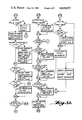
- FIG. 3 is a flow diagram illustration of the operation sequence of the preferred embodiment of the present invention.
- FIG. 1 illustrates a series of sampling tubes 13-13m which are generally positioned underground in the neighborhood of tanks, pipes, and other containments from which leakage of liquids or vapors are to be detected.
- a portion of the leakage vapors, or a portion of the vaporized components of the leakage liquids, are drawn into these sampling tubes by means described below; the relative concentration of such vapors in the air surrounding a given sampling tube being related to the quantity of leakage, the rate of leakage, the distance between the sampling tube and the leakage, the nature of the leakage material, and other lesser effects.
- the number of sampling tubes will depend on the number and size of tanks, pipes, and containments to be monitored.
- sampling tubes may be such as a slotted small diameter pipe that might be placed in the soil near the containment or tank being monitored, or it might be a simple tube with a fitting to attach to a multiwalled tank, whereby the interstitial space between the walls could be monitored.
- each sampling tube 13 Connected to each sampling tube 13 is a flow conditioner 14.
- the flow conditioner filters particulate matter from the air/vapor sample and presents a fixed pneumatic restriction to the sample as it is drawn through the flow conditioner.
- a one way valve within the flow conditioner reduces the restriction to air which may be blown out of the sampling tube 13.
- the system measures the vacuum restrictions and will compensate for such abnormalities as liquid rather than air/vapor samples being present, cut or pinched transport tube 15, etc.
- Transport tubes 15-15m conduct the air/vapor samples from flow conditioners 14-14m to valves 19-19m and alternately conduct air in the reverse direction.
- sampling tube 13, flow conditioner 14, transport tube 15, and valve 19 is installed to sample an area which presents a representative level of ambient vapors, but not localized leakage vapors.
- the sample vapors obtained via this one path are used to calibrate the machine and compensate for changes in the environment, such as smog, ozone, etc., which could otherwise degrade system accuracy.
- sampling tube 13, flow conditioner 14, and transport tube 15 are of a different physical configuration serves as means to induce known vapor mixtures into the machine for the purpose of verification of calibration and other maintenance tests.
- the valves 19-19m connect, generally in a sequential manner, the transport tubes 15-15m to a single collection manifold 17, the design of which separates the air/vapor samples from any liquid which may have been entrapped due to condensation, or for any of reason, in the transport tubes 15-15m.
- Liquid level switch 21 operates if the liquid trapped in the manifold 17 exceeds a predetermined level.
- the pressure transducer 23 provides a signal which indicates the pressure or vacuum level of the manifold 17. Numerous information on system performance is contained therein. Measuring the vacuum level with all valves 19-19m closed can provide early warning of leaking valves or a failing vacuum source. Remeasuring the vacuum level with a particular valve 19 open an all other valves 19-19m closed verifies that the particular sample path of transport tube 15 and flow conditioner 14 are not blocked and not leaking, and that sample tube 13 is not immersed in liquid.
- Filters 25 and 59 remove particulate matter that may have entered various system components during installation or may be introduced through the exhaust port 61. It will be shown that the exhaust port 61 normally vents the sampled vapors from the system, but also is used as the inlet for air when the system blows down the sample paths 13-13m, 14-14m, and 15-15n.
- Air/vapor samples from the manifold 17 pass through the filter 25 and into the cavity 27 which is rendered explosion proof by the choice of thick, strong walls, sturdy fasteners, and long small diameter channels for the inlet of, and withdrawal of, the air/vapor sample.
- Mounted within this cavity is the vapor sensing element 29.
- a Panasonic type EYHS-130P02 gas sensor comprised of sintered semiconductive materials, primarily oxides of iron is the vapor sensing element 29. This sensor presents an electrical resistance which varies as the result of its adsorption of various gasses. The varying resistance of the vapor sensing element 29 is monitored by an analog to digital input port of the microcomputer 35 as referenced in FIG. 2.
- the vacuum pump 43 provides the pressure reduction necessary to transport the air/vapor samples through the system described.
- the pressure/flow characteristics of the vacuum pump 43 are chosen to cause significant changes in the vacuum levels in the manifold 17 as a result of deviations from the normal pneumatic restriction within the sampling path 13, 14, and 15.
- a set of valves 51 and 53 are included to reverse the flow of air or air/vapor mixture within the system. This allows the same vacuum pump 43 to function as a blow-down pump which effectively performs such functions as forcing condensate in transport tubes 15-15m down and out of the system through the flow conditioners 14-14m and sampling tubes 13-13m, and forcing any dangerously high concentration of vapors back down the same path away from the system and operators.
- FIG. 2 is an illustration of the circuitry utilized in the preferred embodiment of the present invention for controlling the soil pollution monitoring system of the present invention.
- the operation of the aforementioned system is controlled by a microcomputer system 35.
- the level of liquid in the manifold 19 is monitored and when it reaches a predetermined level, a signal is provided indicating that the manifold needs to be drained.
- the pressure level in the manifold 17 is monitored and checked for abnormal values.
- the microcomputer in the preferred embodiment is a Motorola MC68705R3. This unit receives signals from the monitoring system of FIG. 1 and provides certain output data on a periodic basis.
- the printer 71 which is driven by an interface circuit 73.
- Alarm signaling is done by a sound transducer 75 which is driven by an amplifier 77 through the volume adjustment potentiometer 79. Additional alarm signaling is done by a lamp 81 which is driven by amplifier 83.
- a keyboard 85 is provided for operator intervention in system operation.
- the keyboard is used to set the real time clock 92 and calendar of the system as well as calling for various test modes and service functions, such as feeding printer paper. Specific combinations of key operations will allow monitoring of specific port conditions on a real time basis, will allow calibration checks to be performed, will allow the alarm lamp to be cleared, and will cause the initiation of various manufacturing test and burn-in routines.
- the keyboard 85 is connected to the microcomputer data buss 80 through interface element 94 which may selectively connect or disconnect the keyboard from the data buss.
- Several status switches 91 are included to allow such initial configuration choices as the maximum number of ports to be operated, the alarm threshold level for vapor, the choice of causing the unit to pause when transport tubes might freeze, and the choice of optimizing certain ports for specific contaminants.
- the simplest form of said optimization being the increase of sensitivity for ports which will be sensing the area around a diesel tank; diesel having a lower vaporization rate than gasoline.
- the status switches 91 are coupled to the data buss 80 through interface element 95 which operates in the above described manner of interface element 94.
- the external reset button 65 allows disabling of the alarm tone without any effect on the alarm lamp.
- Temperature sensor 87 presents a varying resistance to the microcomputer 35 analog input. This sensor is used to determine whether the transport tubes 15-15m might be subject to excessive condensation or freezing of vapors being carried therein.
- Resistors 98-98n are driven by latch circuit 93 which is driven by the microcomputer data buss. The resistors 98-98n may be driven to ground, to a positive voltage, or may be driven by an extremely high impedance by the latch 93. The net result is that a pulsating signal between ground and some positive reference voltage may be applied to capacitor 99 through a selected resistance value, because the resistors 98-98n which are connected to high impedance terminals of latch 93 are effectively disconnected.
- resistors which are related as are the adjacent positions in the binary numbering system, are used to yield a resistance range of about 250:1.
- the resistance of this pulse can be matched to the specific sensor and the specific background vapor conditions such that a predetermined voltage pulse appears at the input of the microcomputer 35, when the calibration routine is exercised, due to the resistance divider action between resistors 98-98n and the vapor sensor.
- the capacitor is sufficiently large that it appears as a very low impedance during the pulse, but causes the average dc current through the vapor sensor 29 to be zero.
- the first action after power-up is initialization of the system, partially between start and node 1 and more fully between nodes 1 and 2.
- Node two is the top of the normal operating loop. Between nodes 2 and 3 options switches are verified and any real time printing is done. After node three the system condition switches are read and any corresponding printout requirement flags are set. Next the audible and lit alarm indicators are operated if necessary and the audible alarm reset if the external reset button is pressed.
- node 7 the ambient temperature is checked and a low temperature pause decision is made on the basis of temperature and whether the low temperature pause option is selected.
- node 8 the keyboard is checked for activation of the ⁇ set ⁇ key.
- the system exits to the keyboard routine which will be described later. If the key was not pressed system checks for two flags either of which will terminate the loop and send the system back to node 2. If the loop is not terminated the system then determines whether the weekly operating statement needs to be printed, then whether it is time to print the daily alarm summary. After node 11 the system determines whether it is one of the three daily self calibrate periods, and attempts the calibration if due. At node 20 the system blows down the selected port for 5 minutes to clear condensate and reduce carry over from any previous high vapor concentration in the sensor. The system then draws the sample from the selected port while constantly watching for any sign of extremely high or dangerous vapor levels.
- the active port is closed and fresh air is drawn into the system to purge the high vapor concentration.
- the vacuum level limits are checked and appropriate action taken.
- node 23 the normal measurement of vapor concentration is made and any that indicate a leak are counted during the last two minutes of the port period. On the last pass for the current port the pressure and vapor faults that happened 5 or more times in the last two minutes are counted as single flags.
- the blocks below node 28 merely update the active port for the various conditions that can exist at that time.
- the keyboard routine is shown on sheet 3 of FIG. 3.
- the clear key causes alarms and flags to be cleared.
- the feed key causes paper advancement.
- the clock key causes the clock to be set if the proper numeric data are entered.
- the test key allows access to various diagnostic routines. Note that the excess key time blocks prevent the machine from inadvertently being left in a state in which it is not monitoring.
- microcomputer is programmed by normal computing techniques to operate in accordance with the aforementioned plan. Accordingly a listing of the code has not been included herein.
Abstract
Description
Claims (6)
Priority Applications (1)
| Application Number | Priority Date | Filing Date | Title |
|---|---|---|---|
| US06/681,575 US4618855A (en) | 1984-12-14 | 1984-12-14 | Soil pollution monitoring system |
Applications Claiming Priority (1)
| Application Number | Priority Date | Filing Date | Title |
|---|---|---|---|
| US06/681,575 US4618855A (en) | 1984-12-14 | 1984-12-14 | Soil pollution monitoring system |
Publications (1)
| Publication Number | Publication Date |
|---|---|
| US4618855A true US4618855A (en) | 1986-10-21 |
Family
ID=24735866
Family Applications (1)
| Application Number | Title | Priority Date | Filing Date |
|---|---|---|---|
| US06/681,575 Expired - Lifetime US4618855A (en) | 1984-12-14 | 1984-12-14 | Soil pollution monitoring system |
Country Status (1)
| Country | Link |
|---|---|
| US (1) | US4618855A (en) |
Cited By (24)
| Publication number | Priority date | Publication date | Assignee | Title |
|---|---|---|---|---|
| US4818976A (en) * | 1987-02-26 | 1989-04-04 | Mine Safety Appliances Company | Device for monitoring hydrocarbons in groundwater |
| US4896526A (en) * | 1987-06-09 | 1990-01-30 | Werner Ratfisch | Continuous monitoring of a gas mixture |
| US4896528A (en) * | 1987-11-16 | 1990-01-30 | Lewis Donald E | Tank bottom leak testing and apparatus |
| US5010776A (en) * | 1989-05-04 | 1991-04-30 | Iit Research Institute | Environmental contamination detection and analyzing system and method |
| US5076728A (en) * | 1990-04-25 | 1991-12-31 | Tracer Research Corporation | Landfill liner leak detection system and method |
| US5115666A (en) * | 1990-02-08 | 1992-05-26 | Sentech Corporation | Method of detecting halogen gas in a liquid |
| EP0488120A2 (en) * | 1990-11-26 | 1992-06-03 | Praxair Technology, Inc. | Diagnostic gas monitoring process |
| WO1993004367A1 (en) * | 1991-08-21 | 1993-03-04 | Robert Bosch Gmbh | Device for the measurement of the concentration of pollutants in a fresh-air supply, in particular the fresh-air supply to a vehicle interior |
| US5193380A (en) * | 1990-09-05 | 1993-03-16 | Alcatel Cit | High flow-rate leak detector having three molecular filters |
| US5301538A (en) * | 1992-04-20 | 1994-04-12 | Teledyne Industries, Inc. | Process and apparatus for distributed wide range leak detection, location and alarm for pollutants |
| EP0607984A2 (en) * | 1993-01-22 | 1994-07-27 | Sentech Corporation | Method and apparatus for sampling and detecting gases in a fluid |
| US5340238A (en) * | 1992-08-04 | 1994-08-23 | Tanknology Corporation International | Method and apparatus for testing above ground liquid storage tanks for leaks |
| US5447055A (en) * | 1993-02-09 | 1995-09-05 | Tracer Research Corporation | Automated leak detection apparatus and method |
| US5543623A (en) * | 1986-01-17 | 1996-08-06 | Tti Environmental Inc. | Method for detecting and mitigating underground organic contamination |
| US6339951B1 (en) * | 1999-07-28 | 2002-01-22 | International Lubrication & Fuel Consultants, Inc. | Leak detection and structural assessment |
| US6405135B1 (en) | 2000-07-18 | 2002-06-11 | John J. Adriany | System for remote detection and notification of subterranean pollutants |
| US20030034885A1 (en) * | 2001-08-20 | 2003-02-20 | Catton Edward W. | Medical gas alarm system |
| US6598458B1 (en) | 2002-01-18 | 2003-07-29 | Ut-Battelle, Llc | Automated soil gas monitoring chamber |
| WO2004003537A2 (en) * | 2002-06-28 | 2004-01-08 | Rosemount Analytical Inc. | Device for sensing the concentration of a combustible specie |
| US20060290525A1 (en) * | 2002-09-12 | 2006-12-28 | Andersen Donald P | Gas alert for medical gas system |
| US20120103446A1 (en) * | 2010-10-27 | 2012-05-03 | Askey Computer Corporation | Air Pressure Producing Apparatus |
| CN102454575A (en) * | 2010-10-27 | 2012-05-16 | 亚旭电脑股份有限公司 | Air pressure generator |
| CN102033001B (en) * | 2009-09-24 | 2015-04-15 | 北京化工大学 | Automatic gas sampling process and device thereof at site of accident |
| EP2980583A1 (en) * | 2014-07-29 | 2016-02-03 | Inficon GmbH | Method and device for discrimination between natural gas and swamp gas |
Citations (1)
| Publication number | Priority date | Publication date | Assignee | Title |
|---|---|---|---|---|
| US3209343A (en) * | 1961-12-11 | 1965-09-28 | Nat Lead Co | Multi-station gas detecting apparatus |
-
1984
- 1984-12-14 US US06/681,575 patent/US4618855A/en not_active Expired - Lifetime
Patent Citations (1)
| Publication number | Priority date | Publication date | Assignee | Title |
|---|---|---|---|---|
| US3209343A (en) * | 1961-12-11 | 1965-09-28 | Nat Lead Co | Multi-station gas detecting apparatus |
Cited By (36)
| Publication number | Priority date | Publication date | Assignee | Title |
|---|---|---|---|---|
| US5543623A (en) * | 1986-01-17 | 1996-08-06 | Tti Environmental Inc. | Method for detecting and mitigating underground organic contamination |
| US4818976A (en) * | 1987-02-26 | 1989-04-04 | Mine Safety Appliances Company | Device for monitoring hydrocarbons in groundwater |
| US4896526A (en) * | 1987-06-09 | 1990-01-30 | Werner Ratfisch | Continuous monitoring of a gas mixture |
| US4896528A (en) * | 1987-11-16 | 1990-01-30 | Lewis Donald E | Tank bottom leak testing and apparatus |
| US5010776A (en) * | 1989-05-04 | 1991-04-30 | Iit Research Institute | Environmental contamination detection and analyzing system and method |
| US5115666A (en) * | 1990-02-08 | 1992-05-26 | Sentech Corporation | Method of detecting halogen gas in a liquid |
| US5331840A (en) * | 1990-02-08 | 1994-07-26 | Sentech Corporation | Detection of a gas leaked into a liquid which has been sampled from a plurality of spaces |
| US5076728A (en) * | 1990-04-25 | 1991-12-31 | Tracer Research Corporation | Landfill liner leak detection system and method |
| US5193380A (en) * | 1990-09-05 | 1993-03-16 | Alcatel Cit | High flow-rate leak detector having three molecular filters |
| EP0488120A3 (en) * | 1990-11-26 | 1995-03-01 | Union Carbide Ind Gases Tech | Diagnostic gas monitoring process |
| EP0488120A2 (en) * | 1990-11-26 | 1992-06-03 | Praxair Technology, Inc. | Diagnostic gas monitoring process |
| WO1993004367A1 (en) * | 1991-08-21 | 1993-03-04 | Robert Bosch Gmbh | Device for the measurement of the concentration of pollutants in a fresh-air supply, in particular the fresh-air supply to a vehicle interior |
| US5301538A (en) * | 1992-04-20 | 1994-04-12 | Teledyne Industries, Inc. | Process and apparatus for distributed wide range leak detection, location and alarm for pollutants |
| US5340238A (en) * | 1992-08-04 | 1994-08-23 | Tanknology Corporation International | Method and apparatus for testing above ground liquid storage tanks for leaks |
| EP0607984A2 (en) * | 1993-01-22 | 1994-07-27 | Sentech Corporation | Method and apparatus for sampling and detecting gases in a fluid |
| US5357781A (en) * | 1993-01-22 | 1994-10-25 | Sentech Corporation | Method and apparatus for sampling and detecting gases in a fluid |
| EP0607984A3 (en) * | 1993-01-22 | 1996-07-17 | Sentech Corp | Method and apparatus for sampling and detecting gases in a fluid. |
| US5447055A (en) * | 1993-02-09 | 1995-09-05 | Tracer Research Corporation | Automated leak detection apparatus and method |
| US6339951B1 (en) * | 1999-07-28 | 2002-01-22 | International Lubrication & Fuel Consultants, Inc. | Leak detection and structural assessment |
| US6405135B1 (en) | 2000-07-18 | 2002-06-11 | John J. Adriany | System for remote detection and notification of subterranean pollutants |
| US6987448B2 (en) | 2001-08-20 | 2006-01-17 | Hill-Rom Services, Inc. | Medical gas alarm system |
| US20030034885A1 (en) * | 2001-08-20 | 2003-02-20 | Catton Edward W. | Medical gas alarm system |
| US6598458B1 (en) | 2002-01-18 | 2003-07-29 | Ut-Battelle, Llc | Automated soil gas monitoring chamber |
| US7527717B2 (en) | 2002-06-28 | 2009-05-05 | Rosemount Analytical, Inc. | Sulfur resistant sensors |
| US20040134781A1 (en) * | 2002-06-28 | 2004-07-15 | Pavel Shuk | Sulfur resistant sensors |
| WO2004003537A3 (en) * | 2002-06-28 | 2004-04-29 | Rosemount Analytical Inc | Device for sensing the concentration of a combustible specie |
| WO2004003537A2 (en) * | 2002-06-28 | 2004-01-08 | Rosemount Analytical Inc. | Device for sensing the concentration of a combustible specie |
| US20060290525A1 (en) * | 2002-09-12 | 2006-12-28 | Andersen Donald P | Gas alert for medical gas system |
| CN102033001B (en) * | 2009-09-24 | 2015-04-15 | 北京化工大学 | Automatic gas sampling process and device thereof at site of accident |
| US20120103446A1 (en) * | 2010-10-27 | 2012-05-03 | Askey Computer Corporation | Air Pressure Producing Apparatus |
| CN102454575A (en) * | 2010-10-27 | 2012-05-16 | 亚旭电脑股份有限公司 | Air pressure generator |
| EP2980583A1 (en) * | 2014-07-29 | 2016-02-03 | Inficon GmbH | Method and device for discrimination between natural gas and swamp gas |
| WO2016016036A1 (en) * | 2014-07-29 | 2016-02-04 | Inficon Gmbh | Method and device for discrimination between natural gas and swamp gas |
| CN106715998A (en) * | 2014-07-29 | 2017-05-24 | 因菲肯有限公司 | Method and device for discrimination between natural gas and swamp gas |
| US10338050B2 (en) | 2014-07-29 | 2019-07-02 | Inficon Gmbh | Method and device for discrimination between natural gas and swamp gas |
| CN106715998B (en) * | 2014-07-29 | 2019-12-10 | 因菲肯有限公司 | Method and device for distinguishing between natural gas and biogas |
Similar Documents
| Publication | Publication Date | Title |
|---|---|---|
| US4618855A (en) | Soil pollution monitoring system | |
| US5117677A (en) | Two-stage vacuum monitoring and leak detection system for liquid product containment facilities | |
| EP0670423B1 (en) | Fuel vapor leak detection system | |
| EP0536987B1 (en) | Method of confirming the presence of a leak in a liquid storage tank | |
| US5301538A (en) | Process and apparatus for distributed wide range leak detection, location and alarm for pollutants | |
| JP4049412B2 (en) | Method and apparatus for testing functionality of tank venting device | |
| EP0681101B1 (en) | Conductivity sensor for fuel vapor handling system | |
| CA2121476C (en) | Gas leak sensor system | |
| US5202667A (en) | Electric leakage detector for underground storage tank systems | |
| US5327873A (en) | Malfunction sensing apparatus for a fuel vapor control system | |
| US20020073767A1 (en) | Method for measuring chemical emissions | |
| US5560243A (en) | Device for venting a fuel tank and a process for checking the functional capability of the device | |
| JPH11316171A (en) | Inspection method for functionality of tank aerator in vehicle | |
| JPH07158520A (en) | Evaporative purge flow-rate monitoring system | |
| US4386534A (en) | System for obtaining exhaust samples and analyzing the same | |
| US20030015022A1 (en) | Method and device for diagnosing tank leaks using a reference measuring method | |
| US5339788A (en) | Method and arrangement for conducting a tank-venting diagnosis in a motor vehicle | |
| KR20000068274A (en) | Diagnostic module for testing the tightness of a container | |
| WO1998049439A1 (en) | Method and device for leakage testing in a tank system | |
| EP0197017B1 (en) | A method and a device for detecting leakage of a tube section | |
| JP4789666B2 (en) | Gas pipeline monitoring equipment | |
| US5465614A (en) | Apparatus and method for non-intrusive testing of a motor vehicle canister purge system | |
| US4520652A (en) | System for obtaining exhaust samples and analyzing the same | |
| US4097852A (en) | Fault detector for liquid immersed inductive apparatus | |
| KR100645305B1 (en) | Method for detecting leak of fuel system |
Legal Events
| Date | Code | Title | Description |
|---|---|---|---|
| AS | Assignment |
Owner name: GENELCO, INC., 11649 CHAIRMAN DRIVE, SUITE 16, DAL Free format text: ASSIGNMENT OF ASSIGNORS INTEREST.;ASSIGNORS:HANSELKA, REINHARD;HARDING, ROBERT C.;OLSEN, EDWARD H.;REEL/FRAME:004545/0352 Effective date: 19860414 Owner name: GENELCO, INC., A CORP. OF TEXAS, TEXAS Free format text: ASSIGNMENT OF ASSIGNORS INTEREST;ASSIGNORS:HANSELKA, REINHARD;HARDING, ROBERT C.;OLSEN, EDWARD H.;REEL/FRAME:004545/0352 Effective date: 19860414 |
|
| STCF | Information on status: patent grant |
Free format text: PATENTED CASE |
|
| AS | Assignment |
Owner name: ARIZONA INSTRUMENT CORPORATION, 1100 EAST UNIVERSI Free format text: ASSIGNMENT OF ASSIGNORS INTEREST.;ASSIGNOR:GENELCO, INC.;REEL/FRAME:004853/0755 Effective date: 19880130 Owner name: ARIZONA INSTRUMENT CORPORATION, ARIZONA Free format text: ASSIGNMENT OF ASSIGNORS INTEREST;ASSIGNOR:GENELCO, INC.;REEL/FRAME:004853/0755 Effective date: 19880130 |
|
| FEPP | Fee payment procedure |
Free format text: PAYOR NUMBER ASSIGNED (ORIGINAL EVENT CODE: ASPN); ENTITY STATUS OF PATENT OWNER: SMALL ENTITY |
|
| FPAY | Fee payment |
Year of fee payment: 4 |
|
| AS | Assignment |
Owner name: SILICON VALLEY BANK, CALIFORNIA Free format text: ASSIGNMENT OF ASSIGNORS INTEREST;ASSIGNOR:ARIZONA INSTRUMENT CORPORATION;REEL/FRAME:006568/0696 Effective date: 19930430 |
|
| AS | Assignment |
Owner name: SILICON VALLEY BANK, CALIFORNIA Free format text: ASSIGNMENT OF ASSIGNORS INTEREST;ASSIGNOR:ARIZONA INSTRUMENT CORPORATION;REEL/FRAME:006653/0171 Effective date: 19930430 |
|
| FEPP | Fee payment procedure |
Free format text: PAYER NUMBER DE-ASSIGNED (ORIGINAL EVENT CODE: RMPN); ENTITY STATUS OF PATENT OWNER: SMALL ENTITY Free format text: PAYOR NUMBER ASSIGNED (ORIGINAL EVENT CODE: ASPN); ENTITY STATUS OF PATENT OWNER: SMALL ENTITY |
|
| FPAY | Fee payment |
Year of fee payment: 8 |
|
| FEPP | Fee payment procedure |
Free format text: PAYER NUMBER DE-ASSIGNED (ORIGINAL EVENT CODE: RMPN); ENTITY STATUS OF PATENT OWNER: SMALL ENTITY Free format text: PAYOR NUMBER ASSIGNED (ORIGINAL EVENT CODE: ASPN); ENTITY STATUS OF PATENT OWNER: SMALL ENTITY |
|
| FPAY | Fee payment |
Year of fee payment: 12 |
|
| AS | Assignment |
Owner name: SILICON VALLEY BANK, CALIFORNIA Free format text: RELEASE BY SECURED PARTY;ASSIGNOR:ARIZONA INSTRUMENT CORPORATION;REEL/FRAME:009756/0046 Effective date: 19990201 Owner name: SILICON VALLEY BANK, CALIFORNIA Free format text: RELEASE BY SECURED PARTY;ASSIGNOR:ARIZONA INSTRUMENT CORPORATION;REEL/FRAME:009748/0995 Effective date: 19990201 |
|
| AS | Assignment |
Owner name: IMPERIAL BANK, CALIFORNIA Free format text: SECURITY INTEREST;ASSIGNOR:ARIZONA INSTRUMENTS CORP.;REEL/FRAME:010018/0201 Effective date: 19980630 |
|
| AS | Assignment |
Owner name: NATIONAL ENVIRONMENTAL SERVICE CO., OKLAHOMA Free format text: ASSIGNMENT OF ASSIGNORS INTEREST;ASSIGNOR:ARIZONA INSTRUMENT CORPORATION;REEL/FRAME:010485/0758 Effective date: 19991214 |
|
| AS | Assignment |
Owner name: BANK ONE, OKLAHOMA, NA, OKLAHOMA Free format text: SECURITY AGREEMENT;ASSIGNOR:NESCO, INC., AN OKLAHOMA CORPORATION;REEL/FRAME:010927/0786 Effective date: 20000512 |
|
| AS | Assignment |
Owner name: SUMMIT HOLDINGS, INC., OKLAHOMA Free format text: ASSIGNMENT OF ASSIGNORS INTEREST;ASSIGNOR:NESCO, INC. (F/K/A NATIONAL ENVIRONMENTAL SERVICE COMPANY);REEL/FRAME:013240/0262 Effective date: 20020429 |