US4616683A - Particle-free dockable interface for integrated circuit processing - Google Patents
Particle-free dockable interface for integrated circuit processing Download PDFInfo
- Publication number
- US4616683A US4616683A US06/721,332 US72133285A US4616683A US 4616683 A US4616683 A US 4616683A US 72133285 A US72133285 A US 72133285A US 4616683 A US4616683 A US 4616683A
- Authority
- US
- United States
- Prior art keywords
- doors
- interface
- cassette
- canopy
- air
- Prior art date
- Legal status (The legal status is an assumption and is not a legal conclusion. Google has not performed a legal analysis and makes no representation as to the accuracy of the status listed.)
- Expired - Fee Related
Links
Images


Classifications
-
- H—ELECTRICITY
- H01—ELECTRIC ELEMENTS
- H01L—SEMICONDUCTOR DEVICES NOT COVERED BY CLASS H10
- H01L21/00—Processes or apparatus adapted for the manufacture or treatment of semiconductor or solid state devices or of parts thereof
- H01L21/67—Apparatus specially adapted for handling semiconductor or electric solid state devices during manufacture or treatment thereof; Apparatus specially adapted for handling wafers during manufacture or treatment of semiconductor or electric solid state devices or components ; Apparatus not specifically provided for elsewhere
- H01L21/677—Apparatus specially adapted for handling semiconductor or electric solid state devices during manufacture or treatment thereof; Apparatus specially adapted for handling wafers during manufacture or treatment of semiconductor or electric solid state devices or components ; Apparatus not specifically provided for elsewhere for conveying, e.g. between different workstations
- H01L21/67763—Apparatus specially adapted for handling semiconductor or electric solid state devices during manufacture or treatment thereof; Apparatus specially adapted for handling wafers during manufacture or treatment of semiconductor or electric solid state devices or components ; Apparatus not specifically provided for elsewhere for conveying, e.g. between different workstations the wafers being stored in a carrier, involving loading and unloading
- H01L21/67775—Docking arrangements
Definitions
- IC processing yield has long been a major concern in integrated circuit (IC) manufacturing.
- a major cause of IC processing failures is the existence of particles such as dust in the processing environment.
- Conventional IC processing is therefore done in a clean room in which the air is continuously circulated and filtered in an attempt to remove the airborne particles.
- personnel are usually clothed in special suits in an attempt to reduce the number of particles introduced as the workers move about the clean room.
- many of the most vulnerable IC process steps are further contained beneath laminar flow down-drafts of filtered air to provide added protection from local sources of particulate contamination.
- the present invention is a departure from the use of a conventional clean room in the fabrication of ICs.
- a novel standardized mechanical interface (SMIF) system is utilized that reduces particle contamination by significantly reducing particle fluxes onto wafers. This is done by mechanically assuring that during transportation, storage, and most processing steps, the gaseous media surrounding the wafers is essentially stationary relative to the wafers, and that particles from exterior "ambient" environments cannot enter the wafer environments.
- the SMIF system of wafer handling reduces wafer particle contamination by as much as ten times when compared to conventional Class 100 clean room wafer handling practice.
- IC manufacturing can proceed in a non-clean facility. Thus, not only is the expense and inconvenience of a clean room eliminated, but also process yields can be maintained or even improved for high density VLSI processes due to the lower concentration of particle contamination.
- the SMIF system therefore consists of two parts: (1) a clean gas filled canopy around the wafer handling apparatus of each piece of processing equipment; and (2) a small, clean, still-gas box to carry wafers from machine to machine.
- the various pieces of the system are mechanically interfaced without the need of an air-lock by means of unique particle-free dockable doors which consist of a door on each piece of equipment that fit together to trap particles which have accumulated from the dirty ambient environment on the outer surfaces of the doors.
- the doors Once linked together, the doors are moved as a unit into the clean interior space, thus opening a particle-free interface between the system components. Wafers are then moved through the system by mechanical arms and elevators without human intrusion.
- the actual wafer movement can also be fully automated through the use of robotic material handlers to further increase productivity.
- FIG. 1 shows a first SMIF subsystem component, a canopy, according to a preferred embodiment of the present invention.
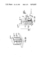
- FIGS. 2A and 2B show a second SMIF subsystem component, a cassette port, according to a preferred embodiment of the present invention.
- FIGS. 3A, 3B and 3C show three versions of a third SMIF subsystem component, a cassette manipulator, according to a preferred embodiment of the present invention.
- FIG. 4 shows the canopy interfaced to the cassette port according to a preferred embodiment of the present invention.
- FIG. 5 shows an alternative embodiment of an interface as shown in FIG. 4
- FIG. 6 shows a SMIF box storage unit according to a preferred embodiment of the present invention.
- FIG. 7 shows a cassette storage unit according to a preferred embodiment of the present invention.
- FIG. 8 shows a system interlock according to a preferred embodiment of the present invention.
- the SMIF system has two parts:
- the SMIF system is built from several of the small clean air boxes and canopies to form SMIF subsystems, each of which are built from three SMIF subsystem components.
- the first SMIF subsystem component as shown in FIG. 1 is the canopy 10.
- the canopy 10 is an easily removable shield that covers the wafer handling mechanisms of each piece of processing equipment 15 (e.g., photoresist applicators, mask aligners, inspection equipment, etc.).
- the canopy 10 is constructed of transparent plastic such as Lexan to facilitate inspection and/or maintenance within the canopy 10 which may later become necessary.
- the other subsystem components are a SMIF cassette port 20 and a SMIF cassette manipulator 30 which are bolted onto the canopy 10 in locations that allow easy movement within the canopy 10. Because the canopy 10 encloses the handling mechanisms of the processing equipment 15, there is no need to enclose the processing equipment 15 within a clean room.
- FIG. 2A shows the details of the SMIF cassette port 20.
- the port 20 is typically mounted on an horizontal surface 40 of the canopy 10 by means of a canopy mounting plate 50.
- the port 20 further consists of a port door 60 and an elevator mechanism 70 that transports a cassette 80 containing the IC wafers 82 into the interior of the canopy 10.
- the wafers 82 are held in the cassette 80 by a wafer dampener 85 as shown in FIG. 2B which is mounted to the door 100 and is activated by the weight of the cassette 80.
- a SMIF box 90 which is used for transporting cassettes 80 from one piece of processing equipment 15 to another, interfaces with the canopy 10 via the SMIF port 20.
- the SMIF box 90 is aligned with the SMIF port 20 by means of a wedge shaped lip 95 and has a door 100 which interlocks with the door 60 on the port 20.
- Doors 60 and 100 together provide a particle-free dockable interface 110, shown in FIG. 2 in the open position, which will be described in detail shortly.
- the interface 110 also provides means to latch the box 90 to the port 20 so that the elevator mechanism 70 can freely transport the cassette 80 between the box 90 and the canopy 10.
- the doors 60 and 100 are designed so that the majority of particles on the exterior surfaces of the doors 60 and 100 are trapped between the doors 60 and 100. Thus, the wafers carried in the cassette 80 are not contaminated when the interface 110 is opened.
- the cassette 80 can be maneuvered as needed by the cassette manipulator 30.
- a manually operated cassette manipulator 30 is shown in FIG. 3.
- the manipulator 30 typically has an arm 120 which is 2-3 feet long and a cassette gripper 130 on the inside (clean air) end and a hand grip 140 on the outside (ambient) end.
- a bearing 150 provides angular and in-out movement for the arm 120 as well as providing an air seal to prevent the intrusion of dirty ambient air.
- the cassette gripper 130 is actuated by gripper switch 155 to hold the cassette 80 which can then be rotated about the vertical axis by a thumb wheel 160 mounted on the hand grip 140.
- a manipulator mounting plate 170 supports the bearing 150 and a port actuation switch 180 which actuates the latching of doors 60 and 100 and the movement of the elevator mechanism 70.
- Mechanical dampers 181 are provided along the three axis of motion of arm 120 to limit the speed of the movement of the gripper 130.
- the manipulator mounting plate 170 is bolted to the canopy 10 as shown in FIG. 1.
- Two alternatives of the cassette manipulator 30 which are often useful are a poker 182 as shown in FIG. 3B and a wafer gripper 183 as shown in FIG. 3C.
- the poker 182 is a cassette manipulator 30 without a gripper 130 used to push objects within the canopy 10.
- the wafer gripper 183 is a cassette manipulator 30 with a three-pronged claw 184 or similar mechanism replacing the cassette gripper 130 so that the wafers can be grasped directly as needed.
- both the canopy 10 and SMIF box 90 described above totally exclude humans and do not utilize constantly moving filtered air to decrease particles on the IC wafer surfaces. Rather, IC cleanliness is achieved by maintaining a still-air interior environment.
- the canopy 10 and box 90 can each be equipped with particle-filtered openings 11 and 91 respectively, (see FIG. 4) to allow continuous equalization between internal and external (ambient) air pressures.
- Such filtered pressure equalization openings 11 and 91 minimize pressure difference and air flow between the canopy 10 and box 90 as the interface 110 is opened and the wafers are moved from the box 90 into the canopy 10.
- FIG. 4 shows a vertically opened version of the SMIF cassette port 20.
- a horizontally opened version is also easily achieved by slight mechanical modifications to the vertically opened version to include a positive spring loaded latch 185 and release cable 187 as shown in FIG. 5 between the doors 60 and 100 since gravity cannot be used to hold the doors together.
- the cassette box 90 is designed to contain one cassette 80 and is only slightly larger than the cassette 80 itself, which holds the IC wafers.
- the cassette box 90 will generally have transparent sides to facilitate observations by humans which may be necessary.
- the particle-free dockable interface 110 mentioned earlier permits clean, particle-free access between two otherwise independent clean environmental systems such as the canopy 10 and the SMIF box 90.
- the interface 110 avoids letting air-borne particles, especially those in the size range between 0.1 to 20 microns, from entering the otherwise clean equipment containers.
- FIG. 4 shows the interconnection of the envelopes of the closed spaces 10 and 90 along a contact area 190.
- it is necessary to open the contact area 190 without exposing the spaces 10 and 90 to the external environment or to the previously external surfaces of doors 60 and 100 of spaces 10 and 90 respectively.
- the portions of the external surfaces of the contact area 190 lying within the contact opening 195 are made to contact one another thereby trapping particles which may exit on the external surfaces between the doors 60 and 100.
- the contact area 190 is then kept in contact while the doors 60 and 100 are moved as a single unit into the space 10.
- the doors 60 and 100 are either circularly or rectangularly symmetrical about axis 200. Before the interface 110 is opened, door 100 is held in place by latches 210 which pass through the walls of spaces 90 by means of airtight bearings or bushings 215. Spaces 10 and 90 are held together in lip 95 by clamp 220.
- a piston 230 of the elevator 70 is located outside of spaces 10 and 90 to conserve space within the enclosures. Piston 230 is coupled to door 60 by an arm 240 and rod 250. The rod 250 passes through the wall of space 10 by means of a bellows 260 which prevents the intrusion of dirty ambient air.
- a vent 270 is provided to allow the equalization of air pressure inside of bellows 260 as the elevator 70 moves and the bellows 260 expands and contracts. Note that the air passing through vent 270 is dirty ambient air, but this does not contaminate space 10 because the bellows is sealed to the inside of space 10 and arm 250.
- latches 210 are released, piston 230 is extended, and the elevator 70 transports both doors 60 and 100 as a unit into space 10, thereby carrying the cassette 80 aligned with the aid of guide lips 275 into space 10 while trapping surface particles between the two doors 60 and 100 and preventing the intrusion of dirty ambient air.
- the doors 60 and 100 need not fit flush with each other along the entire interface 110. In fact, it is desirable that an air gap 290 inside of the outer perimeters 280 and 285 be left between the doors 60 and 100.
- the air gap 290 provides a compressive air space between the doors 60 and 100 so that the dirty air trapped between the doors 60 and 100 does not rush out at high velocity in the plane perpendicular to axis 200 as the doors 60 and 100 are brought together, thereby potentially sweeping part of the dirty trapped air into spaces 10 or 90.
- the air gap 290 also prevents doors 60 and 100 from becoming affixed together by air pressure as could occur if the contact area 190 was a large, closely fitting surface. Typically the air gap 290 will occupy more than 80% of the contact opening 195.
- the doors 60 and 100 should fit together so that perimeters 280 and 285 form one continuous surface. Therefore, joggle 295 where perimeters 280 and 285 meet should be kept as small as possible (e.g., less than 0.010-0.020 inch) since particles on the joggle 295 will be brought within the clean spaces 10 and 90 when the interface 110 is opened. Some particles may be present on the perimeters 280 and 285 so a particle gutter 297 is provided on door 60 to catch any particles which might roll down the perimeters 280 and 285 when the interface 110 is opened. Alternatively, particle gutter 297 can be omitted to permit any particles from the perimeters 280 and 285 to settle all the way to the bottom of the canopy 10.
- FIG. 6 shows a SMIF box storage unit 300.
- the box storage unit 300 is basically an open rack for storing cassette boxes 90.
- FIG. 7 shows a cassette storage unit 320 for storing cassettes 80 holding IC wafers.
- the cassette storage unit 320 is a desiccator box with a canopy 10, port 20, and manipulator 30 added to it.
- the cassette storage unit 320 will typically function as a cassette processing buffer.
- Initial cassette entry into the SMIF system occurs through the system interlock 330 as shown in FIG. 8.
- This is typically a four-foot wide glove box with an access chamber 340 at one end and a SMIF port 20 at the other end.
- the complex movements required to transfer wafers from a new wafer package 345 into a cassette (not shown) necessitates the use of gloves 350 rather than mechanisms.
- Cassettes 80 and wafers enter and leave the SMIF system through the access chamber 340.
- the air filtration unit 355 can contain both a conventional forced air filter and/or a particle collector such as an electrostatic precipitator.
- a particle collector such as an electrostatic precipitator.
- gloves 350 could be used to provide further flexibility of motion within canopy 10. Such gloves 350 are especially useful to provide maintenance within canopy 10 during periods when no IC wafers are present which can be contaminated by the intrusion of outside unfiltered air caused by use of the gloves 350. Filtration units 355 could also be used on the canopy 10 during such maintenance periods to remove any particles which may have intruded.
- ICs are transported in their own closed containers and handling is done by mechanical arms it is also possible to fully automate the IC production facility by the use of stationary or mobile robots which use computer controlled robotic manipulators coupled to the SMIF components. Whether handling is done manually or automatically, by combining the SMIF components with conventional IC processing equipment the IC fabrication area can for the first time be constructed without the need of a conventional clean room environment, while at the same time improving IC cleanliness.
Abstract
A particle-free dockable interface is disclosed for linking together two spaces each enclosing a clean air environment. The interface is composed of interlocking doors on each space which fit together to trap particles which have accumulated from the dirty ambient environment on the outer surfaces of the doors.
Description
This is a continuation of application Ser. No. 536,600 filed 9-28-83 now U.S. Pat. No. 4,532,970, issued Aug. 6, 1985.
Processing yield has long been a major concern in integrated circuit (IC) manufacturing. A major cause of IC processing failures is the existence of particles such as dust in the processing environment. Conventional IC processing is therefore done in a clean room in which the air is continuously circulated and filtered in an attempt to remove the airborne particles. In addition, personnel are usually clothed in special suits in an attempt to reduce the number of particles introduced as the workers move about the clean room. As a final step, many of the most vulnerable IC process steps are further contained beneath laminar flow down-drafts of filtered air to provide added protection from local sources of particulate contamination.
Unfortunately such an environment suffers from several disadvantages. First, such specially designed rooms are not only fairly expensive to construct and maintain, but also working in such an environment is inconvenient. Second since the size of particles which will cause product failure is usually equal to or greater than 1/4 to 1/3 the minimum feature size of the product, it is necessary to continually reduce contamination levels as dimensions are reduced in newer IC products in order to maintain acceptable process yields. This problem becomes especially acute as the minimum feature size drops below one micron for very large scale integrated (VLSI) ICs.
The present invention is a departure from the use of a conventional clean room in the fabrication of ICs. Instead, a novel standardized mechanical interface (SMIF) system is utilized that reduces particle contamination by significantly reducing particle fluxes onto wafers. This is done by mechanically assuring that during transportation, storage, and most processing steps, the gaseous media surrounding the wafers is essentially stationary relative to the wafers, and that particles from exterior "ambient" environments cannot enter the wafer environments. Experiments have shown that the SMIF system of wafer handling reduces wafer particle contamination by as much as ten times when compared to conventional Class 100 clean room wafer handling practice. In addition, since the level of SMIF system particle contamination is independent of the ambient external environment, IC manufacturing can proceed in a non-clean facility. Thus, not only is the expense and inconvenience of a clean room eliminated, but also process yields can be maintained or even improved for high density VLSI processes due to the lower concentration of particle contamination.
Experiments have shown that a significant number of processing defects in VLSI circuits are caused by particles and that many of these particles are related to material handling by humans even if low-particle clothing is employed. A sitting person with light hand, forearm and head movements even with proper clean-room clothing will emit more than 100,000 particles/minute, all larger than 0.3 microns. The SMIF system therefore consists of two parts: (1) a clean gas filled canopy around the wafer handling apparatus of each piece of processing equipment; and (2) a small, clean, still-gas box to carry wafers from machine to machine. The various pieces of the system are mechanically interfaced without the need of an air-lock by means of unique particle-free dockable doors which consist of a door on each piece of equipment that fit together to trap particles which have accumulated from the dirty ambient environment on the outer surfaces of the doors. Once linked together, the doors are moved as a unit into the clean interior space, thus opening a particle-free interface between the system components. Wafers are then moved through the system by mechanical arms and elevators without human intrusion. The actual wafer movement can also be fully automated through the use of robotic material handlers to further increase productivity. Thus by eliminating human handling of IC wafers and maintaining the wafers in a still-air environment throughout the majority of the IC process, particles are reduced and process yield is increased.
FIG. 1 shows a first SMIF subsystem component, a canopy, according to a preferred embodiment of the present invention.
FIGS. 2A and 2B show a second SMIF subsystem component, a cassette port, according to a preferred embodiment of the present invention.
FIGS. 3A, 3B and 3C show three versions of a third SMIF subsystem component, a cassette manipulator, according to a preferred embodiment of the present invention.
FIG. 4 shows the canopy interfaced to the cassette port according to a preferred embodiment of the present invention.
FIG. 5 shows an alternative embodiment of an interface as shown in FIG. 4
FIG. 6 shows a SMIF box storage unit according to a preferred embodiment of the present invention.
FIG. 7 shows a cassette storage unit according to a preferred embodiment of the present invention.
FIG. 8 shows a system interlock according to a preferred embodiment of the present invention.
Conceptually, the SMIF system has two parts:
(1) a clean air canopy around the wafer handling apparatus of each piece of processing equipment; and
(2) a small clean air box to carry wafers from machine to machine.
In practice, the SMIF system is built from several of the small clean air boxes and canopies to form SMIF subsystems, each of which are built from three SMIF subsystem components.
The first SMIF subsystem component as shown in FIG. 1 is the canopy 10. The canopy 10 is an easily removable shield that covers the wafer handling mechanisms of each piece of processing equipment 15 (e.g., photoresist applicators, mask aligners, inspection equipment, etc.). Generally, the canopy 10 is constructed of transparent plastic such as Lexan to facilitate inspection and/or maintenance within the canopy 10 which may later become necessary. The other subsystem components are a SMIF cassette port 20 and a SMIF cassette manipulator 30 which are bolted onto the canopy 10 in locations that allow easy movement within the canopy 10. Because the canopy 10 encloses the handling mechanisms of the processing equipment 15, there is no need to enclose the processing equipment 15 within a clean room.
FIG. 2A shows the details of the SMIF cassette port 20. The port 20 is typically mounted on an horizontal surface 40 of the canopy 10 by means of a canopy mounting plate 50. The port 20 further consists of a port door 60 and an elevator mechanism 70 that transports a cassette 80 containing the IC wafers 82 into the interior of the canopy 10. The wafers 82 are held in the cassette 80 by a wafer dampener 85 as shown in FIG. 2B which is mounted to the door 100 and is activated by the weight of the cassette 80.
A SMIF box 90, which is used for transporting cassettes 80 from one piece of processing equipment 15 to another, interfaces with the canopy 10 via the SMIF port 20. The SMIF box 90 is aligned with the SMIF port 20 by means of a wedge shaped lip 95 and has a door 100 which interlocks with the door 60 on the port 20. Doors 60 and 100 together provide a particle-free dockable interface 110, shown in FIG. 2 in the open position, which will be described in detail shortly. The interface 110 also provides means to latch the box 90 to the port 20 so that the elevator mechanism 70 can freely transport the cassette 80 between the box 90 and the canopy 10. The doors 60 and 100 are designed so that the majority of particles on the exterior surfaces of the doors 60 and 100 are trapped between the doors 60 and 100. Thus, the wafers carried in the cassette 80 are not contaminated when the interface 110 is opened.
Once the cassette 80 is within the canopy 10, the cassette 80 can be maneuvered as needed by the cassette manipulator 30. A manually operated cassette manipulator 30 is shown in FIG. 3. The manipulator 30 typically has an arm 120 which is 2-3 feet long and a cassette gripper 130 on the inside (clean air) end and a hand grip 140 on the outside (ambient) end. A bearing 150 provides angular and in-out movement for the arm 120 as well as providing an air seal to prevent the intrusion of dirty ambient air. The cassette gripper 130 is actuated by gripper switch 155 to hold the cassette 80 which can then be rotated about the vertical axis by a thumb wheel 160 mounted on the hand grip 140. A manipulator mounting plate 170 supports the bearing 150 and a port actuation switch 180 which actuates the latching of doors 60 and 100 and the movement of the elevator mechanism 70. Mechanical dampers 181 are provided along the three axis of motion of arm 120 to limit the speed of the movement of the gripper 130. The manipulator mounting plate 170 is bolted to the canopy 10 as shown in FIG. 1. Two alternatives of the cassette manipulator 30 which are often useful are a poker 182 as shown in FIG. 3B and a wafer gripper 183 as shown in FIG. 3C. The poker 182 is a cassette manipulator 30 without a gripper 130 used to push objects within the canopy 10. The wafer gripper 183 is a cassette manipulator 30 with a three-pronged claw 184 or similar mechanism replacing the cassette gripper 130 so that the wafers can be grasped directly as needed.
It should be noted that both the canopy 10 and SMIF box 90 described above totally exclude humans and do not utilize constantly moving filtered air to decrease particles on the IC wafer surfaces. Rather, IC cleanliness is achieved by maintaining a still-air interior environment. The canopy 10 and box 90 can each be equipped with particle-filtered openings 11 and 91 respectively, (see FIG. 4) to allow continuous equalization between internal and external (ambient) air pressures. Such filtered pressure equalization openings 11 and 91 minimize pressure difference and air flow between the canopy 10 and box 90 as the interface 110 is opened and the wafers are moved from the box 90 into the canopy 10. In addition, access to the interiors of the canopy 10 and box 90 are by means of mechanical arms which occupy essentially constant volume within the enclosures so that there is no significant change in interior volume as IC wafers are moved about. Hence, since there is little or no change of interior air pressure during processing, there is no need for air-tight seals on the canopy 10 or box 90 and particles on the IC wafer surfaces are further decreased by inhibiting the movement of air.
FIG. 4 shows a vertically opened version of the SMIF cassette port 20. A horizontally opened version is also easily achieved by slight mechanical modifications to the vertically opened version to include a positive spring loaded latch 185 and release cable 187 as shown in FIG. 5 between the doors 60 and 100 since gravity cannot be used to hold the doors together. The cassette box 90 is designed to contain one cassette 80 and is only slightly larger than the cassette 80 itself, which holds the IC wafers. The cassette box 90 will generally have transparent sides to facilitate observations by humans which may be necessary. The particle-free dockable interface 110 mentioned earlier permits clean, particle-free access between two otherwise independent clean environmental systems such as the canopy 10 and the SMIF box 90. The interface 110 avoids letting air-borne particles, especially those in the size range between 0.1 to 20 microns, from entering the otherwise clean equipment containers.
FIG. 4 shows the interconnection of the envelopes of the closed spaces 10 and 90 along a contact area 190. In the present invention it is necessary to open the contact area 190 without exposing the spaces 10 and 90 to the external environment or to the previously external surfaces of doors 60 and 100 of spaces 10 and 90 respectively. In particular, when the doors 60 and 100 are opened, the portions of the external surfaces of the contact area 190 lying within the contact opening 195 are made to contact one another thereby trapping particles which may exit on the external surfaces between the doors 60 and 100. The contact area 190 is then kept in contact while the doors 60 and 100 are moved as a single unit into the space 10.
The doors 60 and 100 are either circularly or rectangularly symmetrical about axis 200. Before the interface 110 is opened, door 100 is held in place by latches 210 which pass through the walls of spaces 90 by means of airtight bearings or bushings 215. Spaces 10 and 90 are held together in lip 95 by clamp 220. In the specific embodiment shown in FIG. 4, a piston 230 of the elevator 70 is located outside of spaces 10 and 90 to conserve space within the enclosures. Piston 230 is coupled to door 60 by an arm 240 and rod 250. The rod 250 passes through the wall of space 10 by means of a bellows 260 which prevents the intrusion of dirty ambient air. A vent 270 is provided to allow the equalization of air pressure inside of bellows 260 as the elevator 70 moves and the bellows 260 expands and contracts. Note that the air passing through vent 270 is dirty ambient air, but this does not contaminate space 10 because the bellows is sealed to the inside of space 10 and arm 250. To open the interface 110, latches 210 are released, piston 230 is extended, and the elevator 70 transports both doors 60 and 100 as a unit into space 10, thereby carrying the cassette 80 aligned with the aid of guide lips 275 into space 10 while trapping surface particles between the two doors 60 and 100 and preventing the intrusion of dirty ambient air.
In order to trap surface particles between doors 60 and 100 it is only necessary that the doors contact each other uniformly and closely around their outer perimeters 280 and 285 respectively. The doors 60 and 100 need not fit flush with each other along the entire interface 110. In fact, it is desirable that an air gap 290 inside of the outer perimeters 280 and 285 be left between the doors 60 and 100. The air gap 290 provides a compressive air space between the doors 60 and 100 so that the dirty air trapped between the doors 60 and 100 does not rush out at high velocity in the plane perpendicular to axis 200 as the doors 60 and 100 are brought together, thereby potentially sweeping part of the dirty trapped air into spaces 10 or 90. The air gap 290 also prevents doors 60 and 100 from becoming affixed together by air pressure as could occur if the contact area 190 was a large, closely fitting surface. Typically the air gap 290 will occupy more than 80% of the contact opening 195.
Ideally, the doors 60 and 100 should fit together so that perimeters 280 and 285 form one continuous surface. Therefore, joggle 295 where perimeters 280 and 285 meet should be kept as small as possible (e.g., less than 0.010-0.020 inch) since particles on the joggle 295 will be brought within the clean spaces 10 and 90 when the interface 110 is opened. Some particles may be present on the perimeters 280 and 285 so a particle gutter 297 is provided on door 60 to catch any particles which might roll down the perimeters 280 and 285 when the interface 110 is opened. Alternatively, particle gutter 297 can be omitted to permit any particles from the perimeters 280 and 285 to settle all the way to the bottom of the canopy 10.
FIG. 6 shows a SMIF box storage unit 300. The box storage unit 300 is basically an open rack for storing cassette boxes 90.
FIG. 7 shows a cassette storage unit 320 for storing cassettes 80 holding IC wafers. The cassette storage unit 320 is a desiccator box with a canopy 10, port 20, and manipulator 30 added to it. The cassette storage unit 320 will typically function as a cassette processing buffer.
Initial cassette entry into the SMIF system occurs through the system interlock 330 as shown in FIG. 8. This is typically a four-foot wide glove box with an access chamber 340 at one end and a SMIF port 20 at the other end. The complex movements required to transfer wafers from a new wafer package 345 into a cassette (not shown) necessitates the use of gloves 350 rather than mechanisms. Cassettes 80 and wafers enter and leave the SMIF system through the access chamber 340. Note that since the internal pressure of the system interlock 330 can change abruptly as human arms are thrust in and out of the gloves 350, it is necessary that the system interlock 330 be tightly constructed to prevent the intrusion of outside unfiltered air and it is also necessary to utilize an air filtration unit 355 on the system interlock 330. The air filtration unit 355 can contain both a conventional forced air filter and/or a particle collector such as an electrostatic precipitator. Although generally less desirable from a particle contamination standpoint than using mechanical manipulators 30 on the canopy 10 as shown in FIG. 1, gloves 350 could be used to provide further flexibility of motion within canopy 10. Such gloves 350 are especially useful to provide maintenance within canopy 10 during periods when no IC wafers are present which can be contaminated by the intrusion of outside unfiltered air caused by use of the gloves 350. Filtration units 355 could also be used on the canopy 10 during such maintenance periods to remove any particles which may have intruded.
Because ICs are transported in their own closed containers and handling is done by mechanical arms it is also possible to fully automate the IC production facility by the use of stationary or mobile robots which use computer controlled robotic manipulators coupled to the SMIF components. Whether handling is done manually or automatically, by combining the SMIF components with conventional IC processing equipment the IC fabrication area can for the first time be constructed without the need of a conventional clean room environment, while at the same time improving IC cleanliness.
Claims (4)
1. An interface between first and second containers comprising:
alignment means for orienting the first container in a fixed position relative to the second container;
a first door for independently sealing the first container;
a second door for independently sealing the second container;
said first and second doors each having a mating outer surface of substantially equal exterior dimensions, so that substantially all contamination which has accumulated on the exterior surface of the doors when the containers are separated will be trapped between said doors when the containers are positioned together with said alignment means; and
elevator means coupled to said doors for transporting said doors into said containers as a single unit while said doors are coupled together at their mating outer surfaces and said doors are held together substantially only by gravity.
2. An interface as in claim 1 wherein said door mating outer surfaces contact substantially only in a region within a limited distance around the entire outer perimeters of said doors, so that the surface area of contact is small relative to the total surface areas of the doors.
3. An interface as in claim 2 wherein the surface area of contact is less than 20% of the total surface areas of the doors.
4. An interface as in claim 1 wherein the trapped contamination comprises particulate matter.
Priority Applications (1)
| Application Number | Priority Date | Filing Date | Title |
|---|---|---|---|
| US06/721,332 US4616683A (en) | 1983-09-28 | 1985-04-08 | Particle-free dockable interface for integrated circuit processing |
Applications Claiming Priority (2)
| Application Number | Priority Date | Filing Date | Title |
|---|---|---|---|
| US06/536,600 US4532970A (en) | 1983-09-28 | 1983-09-28 | Particle-free dockable interface for integrated circuit processing |
| US06/721,332 US4616683A (en) | 1983-09-28 | 1985-04-08 | Particle-free dockable interface for integrated circuit processing |
Related Parent Applications (1)
| Application Number | Title | Priority Date | Filing Date |
|---|---|---|---|
| US06/536,600 Continuation US4532970A (en) | 1983-09-28 | 1983-09-28 | Particle-free dockable interface for integrated circuit processing |
Publications (1)
| Publication Number | Publication Date |
|---|---|
| US4616683A true US4616683A (en) | 1986-10-14 |
Family
ID=27065195
Family Applications (1)
| Application Number | Title | Priority Date | Filing Date |
|---|---|---|---|
| US06/721,332 Expired - Fee Related US4616683A (en) | 1983-09-28 | 1985-04-08 | Particle-free dockable interface for integrated circuit processing |
Country Status (1)
| Country | Link |
|---|---|
| US (1) | US4616683A (en) |
Cited By (41)
| Publication number | Priority date | Publication date | Assignee | Title |
|---|---|---|---|---|
| US4724874A (en) * | 1986-05-01 | 1988-02-16 | Asyst Technologies | Sealable transportable container having a particle filtering system |
| US4739882A (en) * | 1986-02-13 | 1988-04-26 | Asyst Technologies | Container having disposable liners |
| US4746256A (en) * | 1986-03-13 | 1988-05-24 | Roboptek, Inc. | Apparatus for handling sensitive material such as semiconductor wafers |
| US4815912A (en) * | 1984-12-24 | 1989-03-28 | Asyst Technologies, Inc. | Box door actuated retainer |
| US4966519A (en) * | 1985-10-24 | 1990-10-30 | Texas Instruments Incorporated | Integrated circuit processing system |
| WO1990014273A1 (en) * | 1989-05-19 | 1990-11-29 | Asyst Technologies, Inc. | Sealable transportable container having improved latch mechanism |
| US5100287A (en) * | 1989-04-27 | 1992-03-31 | Micron Technology, Inc. | Method of transferring wafers using vacuum |
| US5137063A (en) * | 1990-02-05 | 1992-08-11 | Texas Instruments Incorporated | Vented vacuum semiconductor wafer cassette |
| US5217053A (en) * | 1990-02-05 | 1993-06-08 | Texas Instruments Incorporated | Vented vacuum semiconductor wafer cassette |
| USRE34311E (en) * | 1984-08-30 | 1993-07-13 | Texas Instruments Incorporated | Semiconductor slice cassette transport unit |
| US5261776A (en) * | 1989-04-27 | 1993-11-16 | Micron Technology, Inc. | Vacuum operated wafer transfer apparatus |
| US5263521A (en) * | 1991-03-14 | 1993-11-23 | Sne La Calhene | Device for forming a vane joining two containers in a water proof manner and a design for attaching a container to such a device |
| US5291923A (en) * | 1992-09-24 | 1994-03-08 | Internatinal Business Machines Corporation | Door opening system and method |
| US5339952A (en) * | 1992-06-19 | 1994-08-23 | International Business Machines Corporation | Transfer container for transferring flimsy circuit panels under clean room conditions |
| WO1994022715A1 (en) * | 1993-03-29 | 1994-10-13 | Francis, Lee, Ashley | Transfer port apparatus and method |
| US5364225A (en) * | 1992-06-19 | 1994-11-15 | Ibm | Method of printed circuit panel manufacture |
| US5378107A (en) * | 1993-04-01 | 1995-01-03 | Applied Materials, Inc. | Controlled environment enclosure and mechanical interface |
| US5395198A (en) * | 1992-06-19 | 1995-03-07 | International Business Machines Corporation | Vacuum loading chuck and fixture for flexible printed circuit panels |
| US5433574A (en) * | 1992-05-21 | 1995-07-18 | Shinko Electric Co., Ltd. | Gas purge unit for a portable container |
| US5447699A (en) * | 1993-11-17 | 1995-09-05 | The West Company | Combination container for holding sterilized elements and a sterilizable transfer port |
| US5451131A (en) * | 1992-06-19 | 1995-09-19 | International Business Machines Corporation | Dockable interface airlock between process enclosure and interprocess transfer container |
| US5469963A (en) * | 1992-04-08 | 1995-11-28 | Asyst Technologies, Inc. | Sealable transportable container having improved liner |
| US5482161A (en) * | 1994-05-24 | 1996-01-09 | Fluoroware, Inc. | Mechanical interface wafer container |
| EP0574893A3 (en) * | 1992-06-19 | 1996-01-10 | Ibm | Method of printed circuit panel manufacture |
| US5668056A (en) * | 1990-12-17 | 1997-09-16 | United Microelectronics Corporation | Single semiconductor wafer transfer method and manufacturing system |
| US5674039A (en) * | 1996-07-12 | 1997-10-07 | Fusion Systems Corporation | System for transferring articles between controlled environments |
| US5674123A (en) * | 1995-07-18 | 1997-10-07 | Semifab | Docking and environmental purging system for integrated circuit wafer transport assemblies |
| US5697750A (en) * | 1992-11-06 | 1997-12-16 | Applied Materials, Inc. | Controlled environment enclosure and mechanical interface |
| US5847529A (en) * | 1997-04-18 | 1998-12-08 | Taiwan Semiconductor Manufacturing Co. Ltd. | Robot protection system |
| US5879458A (en) * | 1996-09-13 | 1999-03-09 | Semifab Incorporated | Molecular contamination control system |
| WO1999033726A1 (en) * | 1997-12-24 | 1999-07-08 | Asyst Technologies, Inc. | Smif pod door and port door removal and return system |
| US6045620A (en) * | 1997-07-11 | 2000-04-04 | Applied Materials, Inc. | Two-piece slit valve insert for vacuum processing system |
| EP1015323A1 (en) * | 1997-02-03 | 2000-07-05 | The West Company, Incorporated | System for transferring objects into barrier isolator |
| US20020020751A1 (en) * | 2000-08-04 | 2002-02-21 | Ken Matsumoto | Substrate transfer apparatus, semiconductor manufacturing apparatus, and semiconductor device manufacturing method |
| KR100330480B1 (en) * | 2000-02-17 | 2002-04-01 | 황인길 | Device for retaining wafers |
| US6471037B1 (en) | 1999-09-01 | 2002-10-29 | Canon Kabushiki Kaisha | Semiconductor manufacturing apparatus and method |
| US6517304B1 (en) | 1999-03-31 | 2003-02-11 | Canon Kabushiki Kaisha | Method for transporting substrates and a semiconductor manufacturing apparatus using the method |
| US6551044B1 (en) * | 1999-09-14 | 2003-04-22 | Asm America, Inc. | Bellows isolation for index platforms |
| US6811369B2 (en) | 1999-09-02 | 2004-11-02 | Canon Kabushiki Kaisha | Semiconductor fabrication apparatus, pod carry apparatus, pod carry method, and semiconductor device production method |
| US20120297981A1 (en) * | 2009-12-10 | 2012-11-29 | Entegris, Inc. | Porous barrier for evenly distributed purge gas in a microenvironment |
| US8950624B2 (en) | 2011-12-29 | 2015-02-10 | Giuseppe Sacca | Externally operated alpha port system for use with a rapid transfer port |
Citations (11)
| Publication number | Priority date | Publication date | Assignee | Title |
|---|---|---|---|---|
| GB938311A (en) * | 1960-11-17 | 1963-10-02 | Commissariat Energie Atomique | Device for the removal of dangerous products |
| US3260381A (en) * | 1964-04-29 | 1966-07-12 | Robert N Wagner | Apparatus and method for transferring objects into a conditioned atmosphere |
| US3294670A (en) * | 1963-10-07 | 1966-12-27 | Western Electric Co | Apparatus for processing materials in a controlled atmosphere |
| US4047624A (en) * | 1975-10-21 | 1977-09-13 | Airco, Inc. | Workpiece handling system for vacuum processing |
| US4089341A (en) * | 1975-01-08 | 1978-05-16 | G. Kendall Parmelee | Connector method and apparatus for coupling two systems together while excluding the environment from the system interiors |
| US4201310A (en) * | 1978-02-24 | 1980-05-06 | La Calhene | Bidirectional joining device |
| US4260312A (en) * | 1978-09-27 | 1981-04-07 | United Kingdom Atomic Energy Authority | Apparatus for transferring toxic and radioactive materials |
| US4281691A (en) * | 1978-08-25 | 1981-08-04 | Commissariat A L'energie Atomique | Device for transferring and packaging contaminants such as radioactive products within a leak-tight sheath |
| US4412771A (en) * | 1981-07-30 | 1983-11-01 | The Perkin-Elmer Corporation | Sample transport system |
| US4532970A (en) * | 1983-09-28 | 1985-08-06 | Hewlett-Packard Company | Particle-free dockable interface for integrated circuit processing |
| US4534389A (en) * | 1984-03-29 | 1985-08-13 | Hewlett-Packard Company | Interlocking door latch for dockable interface for integrated circuit processing |
-
1985
- 1985-04-08 US US06/721,332 patent/US4616683A/en not_active Expired - Fee Related
Patent Citations (11)
| Publication number | Priority date | Publication date | Assignee | Title |
|---|---|---|---|---|
| GB938311A (en) * | 1960-11-17 | 1963-10-02 | Commissariat Energie Atomique | Device for the removal of dangerous products |
| US3294670A (en) * | 1963-10-07 | 1966-12-27 | Western Electric Co | Apparatus for processing materials in a controlled atmosphere |
| US3260381A (en) * | 1964-04-29 | 1966-07-12 | Robert N Wagner | Apparatus and method for transferring objects into a conditioned atmosphere |
| US4089341A (en) * | 1975-01-08 | 1978-05-16 | G. Kendall Parmelee | Connector method and apparatus for coupling two systems together while excluding the environment from the system interiors |
| US4047624A (en) * | 1975-10-21 | 1977-09-13 | Airco, Inc. | Workpiece handling system for vacuum processing |
| US4201310A (en) * | 1978-02-24 | 1980-05-06 | La Calhene | Bidirectional joining device |
| US4281691A (en) * | 1978-08-25 | 1981-08-04 | Commissariat A L'energie Atomique | Device for transferring and packaging contaminants such as radioactive products within a leak-tight sheath |
| US4260312A (en) * | 1978-09-27 | 1981-04-07 | United Kingdom Atomic Energy Authority | Apparatus for transferring toxic and radioactive materials |
| US4412771A (en) * | 1981-07-30 | 1983-11-01 | The Perkin-Elmer Corporation | Sample transport system |
| US4532970A (en) * | 1983-09-28 | 1985-08-06 | Hewlett-Packard Company | Particle-free dockable interface for integrated circuit processing |
| US4534389A (en) * | 1984-03-29 | 1985-08-13 | Hewlett-Packard Company | Interlocking door latch for dockable interface for integrated circuit processing |
Cited By (60)
| Publication number | Priority date | Publication date | Assignee | Title |
|---|---|---|---|---|
| USRE34311E (en) * | 1984-08-30 | 1993-07-13 | Texas Instruments Incorporated | Semiconductor slice cassette transport unit |
| US4815912A (en) * | 1984-12-24 | 1989-03-28 | Asyst Technologies, Inc. | Box door actuated retainer |
| US4966519A (en) * | 1985-10-24 | 1990-10-30 | Texas Instruments Incorporated | Integrated circuit processing system |
| US4739882A (en) * | 1986-02-13 | 1988-04-26 | Asyst Technologies | Container having disposable liners |
| US4746256A (en) * | 1986-03-13 | 1988-05-24 | Roboptek, Inc. | Apparatus for handling sensitive material such as semiconductor wafers |
| US4724874A (en) * | 1986-05-01 | 1988-02-16 | Asyst Technologies | Sealable transportable container having a particle filtering system |
| US5100287A (en) * | 1989-04-27 | 1992-03-31 | Micron Technology, Inc. | Method of transferring wafers using vacuum |
| US5261776A (en) * | 1989-04-27 | 1993-11-16 | Micron Technology, Inc. | Vacuum operated wafer transfer apparatus |
| WO1990014273A1 (en) * | 1989-05-19 | 1990-11-29 | Asyst Technologies, Inc. | Sealable transportable container having improved latch mechanism |
| US4995430A (en) * | 1989-05-19 | 1991-02-26 | Asyst Technologies, Inc. | Sealable transportable container having improved latch mechanism |
| US5137063A (en) * | 1990-02-05 | 1992-08-11 | Texas Instruments Incorporated | Vented vacuum semiconductor wafer cassette |
| US5217053A (en) * | 1990-02-05 | 1993-06-08 | Texas Instruments Incorporated | Vented vacuum semiconductor wafer cassette |
| US5668056A (en) * | 1990-12-17 | 1997-09-16 | United Microelectronics Corporation | Single semiconductor wafer transfer method and manufacturing system |
| US5976199A (en) * | 1990-12-17 | 1999-11-02 | United Microelectronics Corp. | Single semiconductor wafer transfer method and manufacturing system |
| US5263521A (en) * | 1991-03-14 | 1993-11-23 | Sne La Calhene | Device for forming a vane joining two containers in a water proof manner and a design for attaching a container to such a device |
| US5611452A (en) * | 1992-04-08 | 1997-03-18 | Asyst Technologies, Inc. | Sealable transportable container having improved liner |
| US5469963A (en) * | 1992-04-08 | 1995-11-28 | Asyst Technologies, Inc. | Sealable transportable container having improved liner |
| KR100298764B1 (en) * | 1992-05-21 | 2001-11-30 | 이노마다 시게오 | Gas purge unit for portable sealed container |
| US5433574A (en) * | 1992-05-21 | 1995-07-18 | Shinko Electric Co., Ltd. | Gas purge unit for a portable container |
| US5364225A (en) * | 1992-06-19 | 1994-11-15 | Ibm | Method of printed circuit panel manufacture |
| US5451131A (en) * | 1992-06-19 | 1995-09-19 | International Business Machines Corporation | Dockable interface airlock between process enclosure and interprocess transfer container |
| US5395198A (en) * | 1992-06-19 | 1995-03-07 | International Business Machines Corporation | Vacuum loading chuck and fixture for flexible printed circuit panels |
| EP0574893A3 (en) * | 1992-06-19 | 1996-01-10 | Ibm | Method of printed circuit panel manufacture |
| US5339952A (en) * | 1992-06-19 | 1994-08-23 | International Business Machines Corporation | Transfer container for transferring flimsy circuit panels under clean room conditions |
| US5291923A (en) * | 1992-09-24 | 1994-03-08 | Internatinal Business Machines Corporation | Door opening system and method |
| US6352403B1 (en) | 1992-11-06 | 2002-03-05 | Applied Materials, Inc. | Controlled environment enclosure and mechanical interface |
| US5697750A (en) * | 1992-11-06 | 1997-12-16 | Applied Materials, Inc. | Controlled environment enclosure and mechanical interface |
| US5425400A (en) * | 1993-03-29 | 1995-06-20 | Lee A. Francis | Transfer port apparatus and method |
| WO1994022715A1 (en) * | 1993-03-29 | 1994-10-13 | Francis, Lee, Ashley | Transfer port apparatus and method |
| US5378107A (en) * | 1993-04-01 | 1995-01-03 | Applied Materials, Inc. | Controlled environment enclosure and mechanical interface |
| US5447699A (en) * | 1993-11-17 | 1995-09-05 | The West Company | Combination container for holding sterilized elements and a sterilizable transfer port |
| US5482161A (en) * | 1994-05-24 | 1996-01-09 | Fluoroware, Inc. | Mechanical interface wafer container |
| US5674123A (en) * | 1995-07-18 | 1997-10-07 | Semifab | Docking and environmental purging system for integrated circuit wafer transport assemblies |
| US6120371A (en) * | 1995-07-18 | 2000-09-19 | Semifab Incorporated | Docking and environmental purging system for integrated circuit wafer transport assemblies |
| US5848933A (en) * | 1995-07-18 | 1998-12-15 | Semifab, Incorporated | Docking and environmental purging system for integrated circuit wafer transport assemblies |
| DE19726305C2 (en) * | 1996-07-12 | 2003-06-05 | Fusion Systems Corp | System for transporting objects between environments with controlled conditions |
| US5674039A (en) * | 1996-07-12 | 1997-10-07 | Fusion Systems Corporation | System for transferring articles between controlled environments |
| US6368411B2 (en) | 1996-09-13 | 2002-04-09 | Semifab Incorporated | Molecular contamination control system |
| US6042651A (en) * | 1996-09-13 | 2000-03-28 | Semifab Incorporated | Molecular contamination control system |
| US5879458A (en) * | 1996-09-13 | 1999-03-09 | Semifab Incorporated | Molecular contamination control system |
| US6221163B1 (en) | 1996-09-13 | 2001-04-24 | Semifab Incorporated | Molecular contamination control system |
| EP1015323A4 (en) * | 1997-02-03 | 2006-08-09 | West Co | System for transferring objects into barrier isolator |
| EP1015323A1 (en) * | 1997-02-03 | 2000-07-05 | The West Company, Incorporated | System for transferring objects into barrier isolator |
| US5847529A (en) * | 1997-04-18 | 1998-12-08 | Taiwan Semiconductor Manufacturing Co. Ltd. | Robot protection system |
| US6045620A (en) * | 1997-07-11 | 2000-04-04 | Applied Materials, Inc. | Two-piece slit valve insert for vacuum processing system |
| WO1999033726A1 (en) * | 1997-12-24 | 1999-07-08 | Asyst Technologies, Inc. | Smif pod door and port door removal and return system |
| US6704998B1 (en) | 1997-12-24 | 2004-03-16 | Asyst Technologies, Inc. | Port door removal and wafer handling robotic system |
| US6517304B1 (en) | 1999-03-31 | 2003-02-11 | Canon Kabushiki Kaisha | Method for transporting substrates and a semiconductor manufacturing apparatus using the method |
| US6471037B1 (en) | 1999-09-01 | 2002-10-29 | Canon Kabushiki Kaisha | Semiconductor manufacturing apparatus and method |
| US6759334B2 (en) | 1999-09-01 | 2004-07-06 | Canon Kabushiki Kaisha | Semiconductor manufacturing apparatus and method |
| US6811369B2 (en) | 1999-09-02 | 2004-11-02 | Canon Kabushiki Kaisha | Semiconductor fabrication apparatus, pod carry apparatus, pod carry method, and semiconductor device production method |
| US6551044B1 (en) * | 1999-09-14 | 2003-04-22 | Asm America, Inc. | Bellows isolation for index platforms |
| KR100330480B1 (en) * | 2000-02-17 | 2002-04-01 | 황인길 | Device for retaining wafers |
| US20020020751A1 (en) * | 2000-08-04 | 2002-02-21 | Ken Matsumoto | Substrate transfer apparatus, semiconductor manufacturing apparatus, and semiconductor device manufacturing method |
| US7147166B2 (en) | 2000-08-04 | 2006-12-12 | Canon Kabushiki Kaisha | Substrate transfer apparatus, semiconductor manufacturing apparatus, and semiconductor device manufacturing method |
| US20120297981A1 (en) * | 2009-12-10 | 2012-11-29 | Entegris, Inc. | Porous barrier for evenly distributed purge gas in a microenvironment |
| US9054144B2 (en) * | 2009-12-10 | 2015-06-09 | Entegris, Inc. | Porous barrier for evenly distributed purge gas in a microenvironment |
| KR101832512B1 (en) | 2009-12-10 | 2018-02-26 | 엔테그리스, 아이엔씨. | Porous barrier for evenly distributed purge gas in a microenvironment |
| US10032660B2 (en) | 2009-12-10 | 2018-07-24 | Entegris, Inc. | Porous barrier for evenly distributed purge gas in a microenvironment |
| US8950624B2 (en) | 2011-12-29 | 2015-02-10 | Giuseppe Sacca | Externally operated alpha port system for use with a rapid transfer port |
Similar Documents
| Publication | Publication Date | Title |
|---|---|---|
| US4532970A (en) | Particle-free dockable interface for integrated circuit processing | |
| US4616683A (en) | Particle-free dockable interface for integrated circuit processing | |
| US4534389A (en) | Interlocking door latch for dockable interface for integrated circuit processing | |
| EP0138473A2 (en) | System for integrated circuit processing | |
| US5401212A (en) | Environmental control system | |
| US4815912A (en) | Box door actuated retainer | |
| US5752796A (en) | Vacuum integrated SMIF system | |
| US5451131A (en) | Dockable interface airlock between process enclosure and interprocess transfer container | |
| US5740845A (en) | Sealable, transportable container having a breather assembly | |
| JP4741180B2 (en) | Apparatus and method for protecting and transporting a reticle | |
| US5431599A (en) | Environmental control system | |
| JP3576162B2 (en) | Device for moving articles between containers | |
| US5344365A (en) | Integrated building and conveying structure for manufacturing under ultraclean conditions | |
| US4995430A (en) | Sealable transportable container having improved latch mechanism | |
| US4676709A (en) | Long arm manipulator for standard mechanical interface apparatus | |
| US5195922A (en) | Environmental control system | |
| JP3324960B2 (en) | Article transfer system and method | |
| KR100663322B1 (en) | Cassette buffering within a minienvironment | |
| EP0151336B1 (en) | System for integrated circuit processing | |
| JPS62222625A (en) | Semiconductor manufacturing equipment | |
| EP0288455B1 (en) | Box door actuated retainer | |
| US5364225A (en) | Method of printed circuit panel manufacture | |
| US5395198A (en) | Vacuum loading chuck and fixture for flexible printed circuit panels | |
| EP0574893A2 (en) | Method of printed circuit panel manufacture | |
| JPH1084034A (en) | Method for transferring and using semiconductor wafer carrier and its apparatus |
Legal Events
| Date | Code | Title | Description |
|---|---|---|---|
| FEPP | Fee payment procedure |
Free format text: PAYOR NUMBER ASSIGNED (ORIGINAL EVENT CODE: ASPN); ENTITY STATUS OF PATENT OWNER: LARGE ENTITY |
|
| FPAY | Fee payment |
Year of fee payment: 4 |
|
| REMI | Maintenance fee reminder mailed | ||
| LAPS | Lapse for failure to pay maintenance fees | ||
| FP | Lapsed due to failure to pay maintenance fee |
Effective date: 19941019 |
|
| STCH | Information on status: patent discontinuation |
Free format text: PATENT EXPIRED DUE TO NONPAYMENT OF MAINTENANCE FEES UNDER 37 CFR 1.362 |