US4610272A - Actuating device for a mixing valve - Google Patents
Actuating device for a mixing valve Download PDFInfo
- Publication number
- US4610272A US4610272A US06/662,215 US66221584A US4610272A US 4610272 A US4610272 A US 4610272A US 66221584 A US66221584 A US 66221584A US 4610272 A US4610272 A US 4610272A
- Authority
- US
- United States
- Prior art keywords
- housing
- axis
- valve
- lever
- bend
- Prior art date
- Legal status (The legal status is an assumption and is not a legal conclusion. Google has not performed a legal analysis and makes no representation as to the accuracy of the status listed.)
- Expired - Lifetime
Links
- 230000033001 locomotion Effects 0.000 claims description 10
- 210000003414 extremity Anatomy 0.000 claims description 3
- 238000006073 displacement reaction Methods 0.000 claims description 2
- 210000001364 upper extremity Anatomy 0.000 claims description 2
- 230000000903 blocking effect Effects 0.000 claims 1
- 210000003141 lower extremity Anatomy 0.000 claims 1
- 230000000007 visual effect Effects 0.000 abstract description 4
- XLYOFNOQVPJJNP-UHFFFAOYSA-N water Substances O XLYOFNOQVPJJNP-UHFFFAOYSA-N 0.000 description 10
- VQKWAUROYFTROF-UHFFFAOYSA-N arc-31 Chemical compound O=C1N(CCN(C)C)C2=C3C=C4OCOC4=CC3=NN=C2C2=C1C=C(OC)C(OC)=C2 VQKWAUROYFTROF-UHFFFAOYSA-N 0.000 description 7
- 238000011109 contamination Methods 0.000 description 2
- 239000000463 material Substances 0.000 description 2
- 230000035515 penetration Effects 0.000 description 2
- 238000007599 discharging Methods 0.000 description 1
- 230000001771 impaired effect Effects 0.000 description 1
- 238000012423 maintenance Methods 0.000 description 1
- 239000000203 mixture Substances 0.000 description 1
- 238000012986 modification Methods 0.000 description 1
- 230000004048 modification Effects 0.000 description 1
- 239000011224 oxide ceramic Substances 0.000 description 1
- 229910052574 oxide ceramic Inorganic materials 0.000 description 1
- 230000000284 resting effect Effects 0.000 description 1
- 239000007921 spray Substances 0.000 description 1
Images


Classifications
-
- F—MECHANICAL ENGINEERING; LIGHTING; HEATING; WEAPONS; BLASTING
- F16—ENGINEERING ELEMENTS AND UNITS; GENERAL MEASURES FOR PRODUCING AND MAINTAINING EFFECTIVE FUNCTIONING OF MACHINES OR INSTALLATIONS; THERMAL INSULATION IN GENERAL
- F16K—VALVES; TAPS; COCKS; ACTUATING-FLOATS; DEVICES FOR VENTING OR AERATING
- F16K31/00—Actuating devices; Operating means; Releasing devices
- F16K31/44—Mechanical actuating means
- F16K31/60—Handles
- F16K31/605—Handles for single handle mixing valves
-
- Y—GENERAL TAGGING OF NEW TECHNOLOGICAL DEVELOPMENTS; GENERAL TAGGING OF CROSS-SECTIONAL TECHNOLOGIES SPANNING OVER SEVERAL SECTIONS OF THE IPC; TECHNICAL SUBJECTS COVERED BY FORMER USPC CROSS-REFERENCE ART COLLECTIONS [XRACs] AND DIGESTS
- Y10—TECHNICAL SUBJECTS COVERED BY FORMER USPC
- Y10T—TECHNICAL SUBJECTS COVERED BY FORMER US CLASSIFICATION
- Y10T137/00—Fluid handling
- Y10T137/8593—Systems
- Y10T137/86493—Multi-way valve unit
- Y10T137/86549—Selective reciprocation or rotation
-
- Y—GENERAL TAGGING OF NEW TECHNOLOGICAL DEVELOPMENTS; GENERAL TAGGING OF CROSS-SECTIONAL TECHNOLOGIES SPANNING OVER SEVERAL SECTIONS OF THE IPC; TECHNICAL SUBJECTS COVERED BY FORMER USPC CROSS-REFERENCE ART COLLECTIONS [XRACs] AND DIGESTS
- Y10—TECHNICAL SUBJECTS COVERED BY FORMER USPC
- Y10T—TECHNICAL SUBJECTS COVERED BY FORMER US CLASSIFICATION
- Y10T137/00—Fluid handling
- Y10T137/8593—Systems
- Y10T137/87056—With selective motion for plural valve actuator
- Y10T137/8708—Rotation of actuator arm about its pivot and its axis
Definitions
- Our present invention relates to an actuating device for a mixing valve to control the flow volume as well as the mixing ratio of hot and cold water and, more particularly to an improved, single-handle mixing and control valve, e.g. for domestic water service.
- the German Patent DE-PS No. 30 18 771 describes a mixing valve employing a sphere movably supported in a hemispherical socket which has the supply lines for hot and cold water and the discharge line for the mixture.
- the sphere is supported in the socket in such a manner that a movement about two axes perpendicular to each other is permitted in order to control the flow volume and the mixing ratio.
- Connected to the sphere is a hand lever which extends radially outwardly through a slot within the outer jacket of the valve housing to allow actuation of the sphere by an operator.
- the prior art has the further drawback that the slot covers a substantial part of the length of the jacket because the hand lever also is required to be moved in horizontal direction along a substantial way in order to provide the control of the sphere.
- an actuating device including a hand lever partly accommodated within a respective housing and operatively connected with the valve member of the mixing valve so as to move the valve member about two axes perpendicular to each other whereby the hand lever is provided with a bend in the form of a circular arc segment which projects through the housing and has an inner radius extending from a fixed point located on one of the axes, i.e. a center of curvature preferably on the axis which is transverse to the plane of the hand lever.
- valve member can be displaceable about an axis with which the lever handle is substantially coplanar (first axis) to select the proportions of hot and cold water to be mixed, and about a second axis transverse to the first axis and hence to this plane.
- the center of curvature of the bend which advantageously extends downwardly and outwardly from the portion of the lever connected to the valve member within the housing, can lie at the intersection of these two axes, the bend passing through a slot in a movable housing portion which can be rotated from side to side as the lever is displaced about the first axis.
- the slot in the housing provided to allow penetration of the arc into the interior thereof is considerably reduced and is invisible from the outside as the arc or bend completely fills this slot. Therefore, the housing appears to be of a closed design regardless of the position of the hand lever and provides the mixing valve with an attractive appearance and further allows easy maintenance due to the closed design. Contamination is likewise minimized.
- the hand lever has a grip which extends outwardly from the outer end of the bend at an angle to this outer end which should not exceed 120° and maybe less than 90°.
- This grip can easily be actuated by an operator. It is, however, also possible to connect the grip to the bend via a bracket which extends around the housing so that the bend is located at a position of the housing remote to the operator while the grip is arranged essentially opposite the bend and directed to the operator.
- the movement of the hand lever about the axes can be limited so as to be able to control the flow volume and the mixing ratio of the mixing valve.
- the actuating device includes a plug ring which is fixed to the valve housing in a detachable manner and supports at least one stop against which the hand lever can abut. Consequently, the movement of the hand lever to control the mixing ratio is limited depending on the position of the stop i.e. in what position the plug ring is fixed to the valve housing.
- the valve housing is provided with a serration against which the plug ring engages.
- the bend is provided with an extension accommodating a through-passage in which an adjusting screw is located.
- an adjusting screw By simply adjusting the screw in the passage, the movement of the hand lever between its end positions is controllable, i.e. depending on the position of the screw, the hand lever can selectively open the mixing valve to control the flow volume.
- the lid can be provided with a decorative sheet of any design.
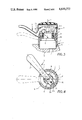
- FIG. 1 is sectional view of a mixing valve provided with an actuating device according to the invention
- FIG. 2 is a side view of the mixing valve of FIG. 1;
- FIG. 3 illustrates the mixing valve according to FIG. 1 and having a hand lever shown in its end positions;
- FIG. 4 is a top view of the mixing valve according to FIG. 3;
- FIG. 5 is a sectional view of the mixing valve provided with a further embodiment of an actuating device according to the invention.
- FIG. 6 is a top view of the mixing valve of FIG. 5;
- FIG. 7 is a top view of a still further embodiment of an actuating device according to the invention.
- FIG. 1 there is shown a mixing valve body or valve housing 1 which includes a socket or base 14 which at its upper extremity is provided with a recess 16 receiving a sleeve 13.
- the sleeve 13 is screwed to the base 14 via a thread connection 15 and embraces a valve cartridge 7 which is formed by two superposed disks made e.g. of oxide ceramics material. Since the structure of valve cartridges is known, a detailed description and illustration of the disks is omitted.
- This cartridge can be a Eurodisk valve cartridge as manufactured by Friedrich Grohe Armaturenfabrik GmbH & Co, see also copending application Ser. No. 556,152 filed Nov. 29, 1983.
- one of the disks is stationarily located in the cartridge while the other disk is movable and provided with a cartridge lever at the end face of the cartridge remote to the socket 14.
- the lever which is illustrated in FIG. 1 and characterized by numeral 71 is movable about two rotational axes. When being rotated about axis 4, the lever 71 and the connected control disk is moved relative to the stationary disk so as to cause a modification of the mixing ratio of cold and hot water while by swivelling about the axis 5, the control disk is radially displaced with respect to the stationary disk so that the flow volume is changed.
- the socket 14 accommodates channels 11 through which the cold and hot water are respectively supplied to the cartridge 7 and a channel 12 for discharging the so-obtained mixing water to e.g. an associated sink.
- the sleeve 13 is step-shaped so as to be provided with an upper shoulder 131 and a lower shoulder 133a. Resting on the upper shoulder 131 is a flange portion 213 of a jacket 21 which forms a part of a top housing portion 2.
- the jacket 21 is cylindrically shaped and has a lower extension abutting on the lower shoulder 133a.
- the flange 213 extends radially inwardly from the jacket and is arranged on the shoulder 131 such that a rotation about axis 4 is possible while an axial displacement is prevented by a snap ring 132.
- a pair of stop cams 61 which oppose each other and are provided to limit pivoting about the axis 5 and thus the fraction of hot water in the mixing ratio as will be described hereinbelow.
- a hand lever For pivoting the cartridge lever 71 about its freedom axes, a hand lever is provided which is generally indicated by numeral 3.
- the hand lever 3 includes a grip portion 32 radially extending at an obtuse angle in direction of an operator and a circular arc-segment bend 31, which may be referred to simply as the arc, whose one end angularly adjoins the grip 32.
- the arc or bend 31 projects through a slot 211 arranged in the jacket 21 into the interior of the top portion 2 and is provided with an extension 33 at its other end.
- the extension At a location adjacent the arc 31, the extension has a stepped through-hole 73 whose lower part is dimensioned such that it fits tightly on the lever 71 of the cartridge 7.
- a countersunk screw 72 By means of a countersunk screw 72, the bend 31 and thus the hand lever 3 is securely fixed in a form-locking manner onto the cartridge lever 71.
- the extension 33 Adjacent the through-hole 73, the extension 33 is provided with a through-passage 74 in which an adjusting screw 331 is arranged.
- the screw 331 is movable within the passage 74 so that its end portion can project beyond the extension 71 to limit pivoting about the axis 5.
- the plug ring 6 or the valve housing 1 can be used as counterstop for the adjusting screw 331, the plug ring 6 or the valve housing 1 can be used.
- a lid 22 is fixed to the jacket 21 via a snap connection 214 so that assembling of the mixing valve and access to the interior thereof is provided in an easy manner.
- the jacket 21 is provided with an elongated slot 211 so as to allow the hand lever 3 to project into the interior of the top housing portion 2 and to be connected to the lever 71.
- the arc 31 which projects through the slot 211 into the interior of the top portion 2 defines an inner contour 311 which is aligned with the outer contour of the jacket 21. Consequently, the inner contour 311 has a radius r measured from the axis 5 constituting the center of the arc 31 which radius is about half the outer diameter of the jacket 21.
- the slot 211 extends from the upper end face of the jacket 21 so as to be accessible from outside when the lid 22 is removed and the hand lever 3, i.e. its arc portion 31 is to be inserted therein.
- the other end 212 of the slot 211 is defined by the radius r of the arc 31 so that once the lid 22 is fixed to the jacket 21, the slot 211 is completely filled by the arc 31.
- the lid 22 extends with its snap portion 214 adjacent the outer contour 312 of the arc 31 and is aligned therewith.
- Assembling of the handle to the valve cartridge 7 can be executed for example in the following manner:
- the sleeve 13 is threaded into the socket 14 by means of a wrench which is engaged on the faces 133.
- the cartridge 7 is fixed tightly and against any rotation within the valve housing 1.
- the jacket 21 is positioned on the sleeve 13 by abutting the flange 213 on the shoulder 131 and secured against axial movement by the snap ring 132.
- the plug ring 6 is then arranged on the serration 62 in any desired manner so as to accordingly limit the pivoting of the hand lever 3 about the axis 4.
- the hand lever 3 can be inserted through the slot 211 which is open at its upper extension towards the outside, and then mounted on the cartridge lever 71. Through tightening of the screw 72, the hand lever 3 is securely fixed on the lever 71 and then the lid 22 is fixed to the jacket via the snap connection 214.
- the lid 22 can simply be removed and the thus accessible adjusting screw 331 can be screwed into the passage 74 so that its end portion projects further beyond the extension 33, thus reducing the pivoting of the handle about the axis 5.
- the lid 22 and the hand lever 3 are removed in order to provide access to the plug ring 6 which is lifted from the serration and reengaged in a different position so that the stop cams 61 occupy a position which further limits the pivoting about the axis 4.
- a hand lever 3a is provided whose bend 31 is arranged at the side of the jacket 21 remote to the operator that is at the rear portion of the mixing valve.
- the bend 31 has an outer extremity located outside the valve housing 1 which extremity is connected to a bracket 34.
- the bracket 34 extends around the jacket 21 and leads to a grip 32a at the side of the mixing valve facing the operator.
- the grip 32a extends at an obtuse angle with respect to the bracket 34 so as to allow easy actuation of the hand lever 3a.
- a hand lever 3b which is formed as a U-bend of round rod material.
- the lever has two shanks 34a, 34b each of which being provided with an arcuate bend 31a at an end remote from the bight connecting these shanks.
- the shanks 34a, 34b run through respective openings 35a, 35b within the jacket 21.
- the bends 31a can be joined by a yoke (not shown) which connects them to the actuating member 71.
Abstract
Description
Claims (10)
Applications Claiming Priority (2)
| Application Number | Priority Date | Filing Date | Title |
|---|---|---|---|
| DE3337968 | 1983-10-19 | ||
| DE19833337968 DE3337968A1 (en) | 1983-10-19 | 1983-10-19 | HAND LEVER FOR HANDLE MIXING VALVES |
Publications (1)
| Publication Number | Publication Date |
|---|---|
| US4610272A true US4610272A (en) | 1986-09-09 |
Family
ID=6212209
Family Applications (1)
| Application Number | Title | Priority Date | Filing Date |
|---|---|---|---|
| US06/662,215 Expired - Lifetime US4610272A (en) | 1983-10-19 | 1984-10-18 | Actuating device for a mixing valve |
Country Status (7)
| Country | Link |
|---|---|
| US (1) | US4610272A (en) |
| EP (1) | EP0140275B1 (en) |
| AT (1) | ATE31357T1 (en) |
| DE (2) | DE3337968A1 (en) |
| DK (1) | DK166041C (en) |
| FI (1) | FI77095C (en) |
| NO (1) | NO159412C (en) |
Cited By (16)
| Publication number | Priority date | Publication date | Assignee | Title |
|---|---|---|---|---|
| US4708172A (en) * | 1985-09-25 | 1987-11-24 | Vargarda Armatur Ab | Device at mixing valves |
| US4739798A (en) * | 1986-11-10 | 1988-04-26 | Botnick Irlin H | Multiple control valve for mixing fluids |
| US4887642A (en) * | 1987-10-27 | 1989-12-19 | Dorf Industries Pty. Ltd. | Single handle mixing tap or valve |
| US5082023A (en) * | 1989-10-31 | 1992-01-21 | Staar S. A. | Single-handle faucet |
| US5329967A (en) * | 1992-07-14 | 1994-07-19 | Friedrich Grohe Aktiengesellschaft | Lever assembly for single-control mixing valve |
| US5363880A (en) * | 1994-01-24 | 1994-11-15 | Hsieh Yung Li | Hot/cold water mixing faucet with water temperature control |
| US5386852A (en) * | 1992-04-30 | 1995-02-07 | Amfag S.R.L. | Flow-rate limiting device in a single-control mixer cartridge for hot and cold water |
| US5494077A (en) * | 1990-01-05 | 1996-02-27 | Toto Ltd. | Hot and cold water mixing discharge device |
| US5522429A (en) * | 1993-11-30 | 1996-06-04 | Friedrich Grohe Aktiengesellschaft | Stroke limiter for single-lever mixing valve |
| US5570720A (en) * | 1991-06-17 | 1996-11-05 | Gustavsberg Vargarda Armatur Ab | Mixing valve of single lever type provided with a device for preventing pressure shock at closing movement of the lever |
| US5730176A (en) * | 1995-03-24 | 1998-03-24 | Friedrich Grohe Ag | Single-control mixing valve with pivotal casing |
| EP0819877A3 (en) * | 1996-07-18 | 1998-08-05 | Friedrich Grohe Aktiengesellschaft | Actuating device for a single handle mixing valve |
| US5899230A (en) * | 1995-11-03 | 1999-05-04 | Galatron Srl | Device to control the rate of flow for values that mix hot and cold water |
| US5983939A (en) * | 1996-07-13 | 1999-11-16 | Friedrich Grohe Ag | Single-control mixing valve |
| US20050000575A1 (en) * | 2003-02-20 | 2005-01-06 | Ugo Pizzi | Single-control mixer tap with improved flow adjustment |
| US20100224812A1 (en) * | 2009-03-04 | 2010-09-09 | Kwc Ag | Sanitary fitting with limitation of water flow |
Families Citing this family (5)
| Publication number | Priority date | Publication date | Assignee | Title |
|---|---|---|---|---|
| DE3510833A1 (en) * | 1985-03-26 | 1986-10-09 | Grohe Armaturen Friedrich | MIXING VALVE |
| DE3607349C2 (en) * | 1986-03-06 | 1995-07-20 | Grohe Armaturen Friedrich | Actuator for one-handle mixer valves |
| DE9300841U1 (en) * | 1993-01-22 | 1993-03-11 | Hans Grohe Gmbh & Co Kg, 7622 Schiltach, De | |
| DE102009008564B4 (en) * | 2009-02-12 | 2011-03-10 | Grohe Ag | plumbing fixture |
| DE102011115390B4 (en) | 2011-10-10 | 2019-02-14 | Grohe Ag | Flow rate adjustment device for a sanitary fitting |
Citations (15)
| Publication number | Priority date | Publication date | Assignee | Title |
|---|---|---|---|---|
| US2635622A (en) * | 1947-08-11 | 1953-04-21 | Jesse C Owens | Antisiphonic ball cock |
| US2864398A (en) * | 1953-05-04 | 1958-12-16 | William P Green | Dual action handles |
| US3168112A (en) * | 1964-01-23 | 1965-02-02 | Hughlin E Klingler | Temperature mixing and diverting valve for domestic plumbing fixtures |
| US3410487A (en) * | 1966-08-29 | 1968-11-12 | Pryde Inc | Faucet |
| DE1963451A1 (en) * | 1969-12-18 | 1971-06-24 | Heinr Schulte & Sohn Kg | Mixer faucet for sanitary facilities with regulating devices for the water flow and the cold and hot water supply |
| DE7232994U (en) * | 1972-12-07 | H Eichelberg & Co Gmbh | Mixer faucet for sanitary facilities | |
| US3964514A (en) * | 1974-07-01 | 1976-06-22 | Masco Corporation Of Indiana | Push-pull single handle water faucet valve |
| US4200596A (en) * | 1978-05-18 | 1980-04-29 | Honda Giken Kogyo Kabushiki Kaisha (Honda Motor Co., Ltd.) | Throttle valve apparatus in an internal combustion engine and its method of operation |
| DE2856300A1 (en) * | 1978-12-27 | 1980-07-03 | Grohe Armaturen Friedrich | Pivoted operating handle for shower mixer valve - which has hole fitting over rotatable cap to which handle is pivoted |
| DE3018180A1 (en) * | 1980-05-13 | 1981-11-19 | Friedrich Grohe Armaturenfabrik Gmbh & Co, 5870 Hemer | Mixing valve hand lever - has transverse end trunnion engaging with control member in valve |
| DE3018771A1 (en) * | 1980-05-16 | 1981-11-26 | Friedrich Grohe Armaturenfabrik Gmbh & Co, 5870 Hemer | Mixing tap for hot and cold water - has hollow ceramic sphere acting as valve member and mixing chamber against spherical seating surface |
| US4325403A (en) * | 1979-05-04 | 1982-04-20 | Gevipi A.G. | Single-control mixing cock with plates made of hard material |
| DE3103891A1 (en) * | 1981-02-05 | 1982-09-02 | Hansa Metallwerke Ag, 7000 Stuttgart | Sanitary single-lever mixer fitting |
| US4375225A (en) * | 1980-12-10 | 1983-03-01 | F M Mattsson Ab | Mixing valve |
| US4387880A (en) * | 1980-10-30 | 1983-06-14 | Oras Oy | Single-grip mixing valve |
-
1983
- 1983-10-19 DE DE19833337968 patent/DE3337968A1/en not_active Withdrawn
-
1984
- 1984-10-04 FI FI843907A patent/FI77095C/en not_active IP Right Cessation
- 1984-10-17 AT AT84112494T patent/ATE31357T1/en not_active IP Right Cessation
- 1984-10-17 DE DE8484112494T patent/DE3468068D1/en not_active Expired
- 1984-10-17 EP EP19840112494 patent/EP0140275B1/en not_active Expired
- 1984-10-18 NO NO844175A patent/NO159412C/en unknown
- 1984-10-18 US US06/662,215 patent/US4610272A/en not_active Expired - Lifetime
- 1984-10-18 DK DK497584A patent/DK166041C/en not_active IP Right Cessation
Patent Citations (15)
| Publication number | Priority date | Publication date | Assignee | Title |
|---|---|---|---|---|
| DE7232994U (en) * | 1972-12-07 | H Eichelberg & Co Gmbh | Mixer faucet for sanitary facilities | |
| US2635622A (en) * | 1947-08-11 | 1953-04-21 | Jesse C Owens | Antisiphonic ball cock |
| US2864398A (en) * | 1953-05-04 | 1958-12-16 | William P Green | Dual action handles |
| US3168112A (en) * | 1964-01-23 | 1965-02-02 | Hughlin E Klingler | Temperature mixing and diverting valve for domestic plumbing fixtures |
| US3410487A (en) * | 1966-08-29 | 1968-11-12 | Pryde Inc | Faucet |
| DE1963451A1 (en) * | 1969-12-18 | 1971-06-24 | Heinr Schulte & Sohn Kg | Mixer faucet for sanitary facilities with regulating devices for the water flow and the cold and hot water supply |
| US3964514A (en) * | 1974-07-01 | 1976-06-22 | Masco Corporation Of Indiana | Push-pull single handle water faucet valve |
| US4200596A (en) * | 1978-05-18 | 1980-04-29 | Honda Giken Kogyo Kabushiki Kaisha (Honda Motor Co., Ltd.) | Throttle valve apparatus in an internal combustion engine and its method of operation |
| DE2856300A1 (en) * | 1978-12-27 | 1980-07-03 | Grohe Armaturen Friedrich | Pivoted operating handle for shower mixer valve - which has hole fitting over rotatable cap to which handle is pivoted |
| US4325403A (en) * | 1979-05-04 | 1982-04-20 | Gevipi A.G. | Single-control mixing cock with plates made of hard material |
| DE3018180A1 (en) * | 1980-05-13 | 1981-11-19 | Friedrich Grohe Armaturenfabrik Gmbh & Co, 5870 Hemer | Mixing valve hand lever - has transverse end trunnion engaging with control member in valve |
| DE3018771A1 (en) * | 1980-05-16 | 1981-11-26 | Friedrich Grohe Armaturenfabrik Gmbh & Co, 5870 Hemer | Mixing tap for hot and cold water - has hollow ceramic sphere acting as valve member and mixing chamber against spherical seating surface |
| US4387880A (en) * | 1980-10-30 | 1983-06-14 | Oras Oy | Single-grip mixing valve |
| US4375225A (en) * | 1980-12-10 | 1983-03-01 | F M Mattsson Ab | Mixing valve |
| DE3103891A1 (en) * | 1981-02-05 | 1982-09-02 | Hansa Metallwerke Ag, 7000 Stuttgart | Sanitary single-lever mixer fitting |
Cited By (19)
| Publication number | Priority date | Publication date | Assignee | Title |
|---|---|---|---|---|
| US4708172A (en) * | 1985-09-25 | 1987-11-24 | Vargarda Armatur Ab | Device at mixing valves |
| AU592368B2 (en) * | 1985-09-25 | 1990-01-11 | Vargarda Armatur A.B. | A mixing valve device |
| US4739798A (en) * | 1986-11-10 | 1988-04-26 | Botnick Irlin H | Multiple control valve for mixing fluids |
| US4887642A (en) * | 1987-10-27 | 1989-12-19 | Dorf Industries Pty. Ltd. | Single handle mixing tap or valve |
| US5082023A (en) * | 1989-10-31 | 1992-01-21 | Staar S. A. | Single-handle faucet |
| US5494077A (en) * | 1990-01-05 | 1996-02-27 | Toto Ltd. | Hot and cold water mixing discharge device |
| US5570720A (en) * | 1991-06-17 | 1996-11-05 | Gustavsberg Vargarda Armatur Ab | Mixing valve of single lever type provided with a device for preventing pressure shock at closing movement of the lever |
| US5386852A (en) * | 1992-04-30 | 1995-02-07 | Amfag S.R.L. | Flow-rate limiting device in a single-control mixer cartridge for hot and cold water |
| US5329967A (en) * | 1992-07-14 | 1994-07-19 | Friedrich Grohe Aktiengesellschaft | Lever assembly for single-control mixing valve |
| US5522429A (en) * | 1993-11-30 | 1996-06-04 | Friedrich Grohe Aktiengesellschaft | Stroke limiter for single-lever mixing valve |
| US5363880A (en) * | 1994-01-24 | 1994-11-15 | Hsieh Yung Li | Hot/cold water mixing faucet with water temperature control |
| US5730176A (en) * | 1995-03-24 | 1998-03-24 | Friedrich Grohe Ag | Single-control mixing valve with pivotal casing |
| US5899230A (en) * | 1995-11-03 | 1999-05-04 | Galatron Srl | Device to control the rate of flow for values that mix hot and cold water |
| US5983939A (en) * | 1996-07-13 | 1999-11-16 | Friedrich Grohe Ag | Single-control mixing valve |
| EP0819877A3 (en) * | 1996-07-18 | 1998-08-05 | Friedrich Grohe Aktiengesellschaft | Actuating device for a single handle mixing valve |
| US5992457A (en) * | 1996-07-18 | 1999-11-30 | Friedrich Grohe Ag | Single-lever mixing valve with override |
| US20050000575A1 (en) * | 2003-02-20 | 2005-01-06 | Ugo Pizzi | Single-control mixer tap with improved flow adjustment |
| US20100224812A1 (en) * | 2009-03-04 | 2010-09-09 | Kwc Ag | Sanitary fitting with limitation of water flow |
| US8418995B2 (en) | 2009-03-04 | 2013-04-16 | Kwc Ag | Sanitary fitting with limitation of water flow |
Also Published As
| Publication number | Publication date |
|---|---|
| FI843907L (en) | 1985-04-20 |
| EP0140275A3 (en) | 1985-10-23 |
| DK166041B (en) | 1993-03-01 |
| FI77095B (en) | 1988-09-30 |
| DK497584A (en) | 1985-04-20 |
| EP0140275B1 (en) | 1987-12-09 |
| FI77095C (en) | 1989-01-10 |
| DE3468068D1 (en) | 1988-01-21 |
| NO159412C (en) | 1988-12-21 |
| NO844175L (en) | 1985-04-22 |
| NO159412B (en) | 1988-09-12 |
| DK166041C (en) | 1993-08-02 |
| DE3337968A1 (en) | 1985-05-02 |
| DK497584D0 (en) | 1984-10-18 |
| FI843907A0 (en) | 1984-10-04 |
| ATE31357T1 (en) | 1987-12-15 |
| EP0140275A2 (en) | 1985-05-08 |
Similar Documents
| Publication | Publication Date | Title |
|---|---|---|
| US4610272A (en) | Actuating device for a mixing valve | |
| US7318450B2 (en) | Mixing cartridge for single-lever mixing faucets | |
| EP0156122B1 (en) | Cold and warm water mixing valve with ceramic discs controlled by a thermostat | |
| CA2089125C (en) | Control cartridge for a single-lever mixer fitting | |
| JPH06221448A (en) | Mixture bibcock for cool and hot water | |
| EP0356402B1 (en) | Mixing valve for hot and cold water | |
| US7314063B2 (en) | Single-lever mixing valve with stirrup-shaped handle | |
| EP2655945A1 (en) | Thermostatic mixing valve with integrated flow diverter | |
| US7406984B2 (en) | Fluid distribution device | |
| US6988669B2 (en) | Thermostatic mixer valve assembled in a cartridge body | |
| CA2210240C (en) | Mixing valve with a hand lever | |
| CA2170966A1 (en) | Mixing valve with a hand lever | |
| RU2114353C1 (en) | Mixing cock valve, spherical valve and spherical valve holder | |
| US7373952B2 (en) | Sanitary outflow fitting | |
| US4705072A (en) | Single-lever mixing fixture | |
| KR20030032051A (en) | Cartridge for sanitary appliances | |
| PT797034E (en) | VALVE | |
| US3998241A (en) | Single control faucet | |
| US4393523A (en) | Tub filling and shower valve | |
| US4651774A (en) | Single-lever mixer | |
| JPH06123369A (en) | Mixing valve for hot water and cold water having two independent adjusting means | |
| US2839083A (en) | Valve handle | |
| US9863127B2 (en) | Sanitary fitting | |
| DK171405B1 (en) | Single lever mixer | |
| US20030019943A1 (en) | Valve element for mixing and flow-rate adjustment in faucets and the like |
Legal Events
| Date | Code | Title | Description |
|---|---|---|---|
| AS | Assignment |
Owner name: FRIEDRICH GROHE ARMATURENFABRIK GMBH & CO., HAUPTS Free format text: ASSIGNMENT OF ASSIGNORS INTEREST.;ASSIGNORS:GOTTWALD, ADOLF;KOSTER, WILFRIED;REEL/FRAME:004344/0721 Effective date: 19841106 |
|
| STCF | Information on status: patent grant |
Free format text: PATENTED CASE |
|
| FEPP | Fee payment procedure |
Free format text: PAYOR NUMBER ASSIGNED (ORIGINAL EVENT CODE: ASPN); ENTITY STATUS OF PATENT OWNER: LARGE ENTITY |
|
| FPAY | Fee payment |
Year of fee payment: 4 |
|
| AS | Assignment |
Owner name: FRIEDRICH GROHE AKTIENGESELLSCHAFT, GERMANY Free format text: CHANGE OF NAME;ASSIGNOR:FRIEDRICH GROHE ARMATURENFABRIK GMBH & CO.;REEL/FRAME:006080/0113 Effective date: 19920123 |
|
| FPAY | Fee payment |
Year of fee payment: 8 |
|
| FPAY | Fee payment |
Year of fee payment: 12 |
|
| AS | Assignment |
Owner name: FRIEDRICH GROHE AG & CO. KG, GERMANY Free format text: CHANGE OF NAME;ASSIGNOR:FRIEDRICH GROHE AG;REEL/FRAME:010822/0875 Effective date: 20000328 |