US4602344A - Method and system for measurement of liquid level in a tank - Google Patents
Method and system for measurement of liquid level in a tank Download PDFInfo
- Publication number
- US4602344A US4602344A US06/664,817 US66481784A US4602344A US 4602344 A US4602344 A US 4602344A US 66481784 A US66481784 A US 66481784A US 4602344 A US4602344 A US 4602344A
- Authority
- US
- United States
- Prior art keywords
- level
- determining
- tank
- substance
- collected average
- Prior art date
- Legal status (The legal status is an assumption and is not a legal conclusion. Google has not performed a legal analysis and makes no representation as to the accuracy of the status listed.)
- Expired - Fee Related
Links
Images

Classifications
-
- G—PHYSICS
- G01—MEASURING; TESTING
- G01F—MEASURING VOLUME, VOLUME FLOW, MASS FLOW OR LIQUID LEVEL; METERING BY VOLUME
- G01F23/00—Indicating or measuring liquid level or level of fluent solid material, e.g. indicating in terms of volume or indicating by means of an alarm
- G01F23/14—Indicating or measuring liquid level or level of fluent solid material, e.g. indicating in terms of volume or indicating by means of an alarm by measurement of pressure
- G01F23/16—Indicating, recording, or alarm devices being actuated by mechanical or fluid means, e.g. using gas, mercury, or a diaphragm as transmitting element, or by a column of liquid
Definitions
- This invention relates to the replenishing of substance within liquid storage tanks and, in particular, replenishing such tanks when the substance in the tanks produces erratic pressure readings when drawn or replenished.
- liquid products are delivered in bulk to a user's site where they are held in a storage tank, from which either intermittent or continuous withdrawal may occur.
- liquid fuels such as domestic heating oil, liquid chemicals employed in manufacturing processes, and liquified gases such as oxygen or nitrogen.
- liquified nitrogen is a source of inert nitrogen gas for submerging various industrial processes and operations. If the supply of nitrogen runs out during a process run, an entire production lot may be destroyed. Nitrogen gas is also used to purge storage tanks from which flammable liquids are being withdrawn to avoid the entrance of air and the subsequent formation of explosive mixtures. Exhaustion of nitrogen during this process can result in an explosion.
- the first method was to anticipate from past experience the rate of withdrawal of liquid from the tank, and to extrapolate in order to estimate the time at which replenishment was needed.
- This approach PG,4 assumed that usage patterns were similar to prior usage patterns. If depletion were more rapid than anticipated because of increased use or leakage, the tank could empty before the normal replenishment time was reached. Likewise, if usage were unexpectedly curtailed, an unnecessary trip by the supplier's delivery vehicle resulted in the addition of only a small amount to top off the tank.
- the second approach was for the user to periodically measure the amount of substance remaining in the tank, and notify the supplier when a delivery was required. This method depended entirely upon the diligence of the user in adhering to a schedule of tank readings and the user's ability to recognize the necessity of a request for a delivery.
- a system for measuring liquid level in a tank updates a prior collected average level of substance in the tank. It continuously determines values of differential pressure within the tank and in accordance with the values of differential pressure, calculates the instantaneous level of substance within the tank. A prior collected average level is stored and is compared with each of the instantaneous values of level thus obtained. On the basis of this comparison a relative weighting factor is determined which weighs the relative contribution of the collected and instantaneous values in determining a new collected value.
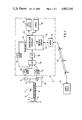
- FIG. 1 is a block diagram of system 10 for measuring liquid level in a tank of the present invention
- FIG. 2 is a flow diagram of portions of system 10 of FIG. 1.
- FIG. 1 shows a block diagram of microprocessor based intelligent remote tank telemetry system 10.
- Tank telemetry system 10 continuously monitors the substance level of a tank 12 containing a cryogenic liquid, having an inlet 38 and an outlet 40 and containing substance space 14 and vapor space 16.
- Pressure sense line 22 couples vapor space 16 to pressure transducer 18 and to differential pressure transducer 20.
- Pressure sense line 24 couples substance space 14 to differential pressure gauge 20.
- System 10 includes three signal conditioners 48, 50 and 52. The outputs of signal conditioners 48, 50 and 52 are multiplexed by multiplexer 46 and the single output of multiplexer 46 is applied to A/D converter 26.
- Microprocessor controller 28 has conventional volatile and non-volatile memory and a time-weighted software-based averager 36 which smooths out erratic substance level determinations.
- Automatic dialing modem 30 is coupled to remote display 34 by telephone lines 32.
- Pressure transducer 18 produces an analog signal proportional to the pressure of vapor space 16.
- Differential pressure transducer 20 produces an analog signal proportional to the difference between the pressure of vapor space 16 and the pressure at the bottom of substance space 14.
- the analog output signals of transducers 18 and 20 are conditioned by signal conditioners 50 and 52 respectively.
- the conditioned signals are multiplexed by multiplexer 46 and applied to A/D converter 26.
- A/D converter 26 converts the multiplexed analog output signals to digital signals and applies these digital signals to microprocessor controller 28. Based upon the signal generated by differential pressure transducer 20 and received from A/D converter 26, microcontroller 28 periodically determines an instantaneous level of substance in substance space 14. This determination requires only a multiplication of the differential pressure signal by a predetermined constant. A typical value for this constant is 27.67. From these intantaneous values of substance level time-weighted averager 36 determines a collected average level. Controller 28 stores the collected average level and recognizes collected average substance levels below a predetermined threshold set point.
- Time-weighted average 36 within controller 28 is particularly useful when the substance within tank 12 is a cryogenic substance because of complications inherent in the storage of cryogenic liquids.
- time-weighted average 36 is provided within controller 28.
- Microprocessor controller 28 applies two values to time-weighted averager 36, (1) the instantaneous tank level signal, as determined from the most recent value of differential pressure applied to microcontroller 28, and (2) the prior collected average level stored within the memory of controller 28.
- the prior collected average is the current level of substance within tank 12 as of the most recent update.
- the instantaneous tank level is the most recent level calculated and may be based upon quiescent differential pressures or upon sample values of erratically fluctuating differential pressures.
- the signal conditioning and multiplexing of the signals from transducers 18, 20 have been omitted from FIG. 2 to simplify the drawing.
- the instantaneous value of tank level supplied to time-weighted averager 36 is converted into a modulo two mantissa and exponent at block 102 of controller 28 before being supplied to time-weighted averager 36. It is converted into a modulo two mantissa and exponent in the following way.
- the intantaneous level determined from the vapor space pressure and the differential pressure is repeatedly divided by two until a mantissa between 0 and 0.5 is produced.
- the number of divisions required to produce such a mantissa is counted and stored in base two form as the exponent.
- the collected average is processed into a modulo two mantissa and exponent in the same manner before being passed to time-weighted averager 36.
- Time-weighted averager 36 compares the exponent of the new instantaneous level with the exponent of the collected average which it received from controller 28. If a change in the exponent is detected at decision 106, a weighting factor is developed in order to weigh the collected average more heavily than the new instantaneous value.
- the weighting factor is determined in block 112 by calculating or determining, at block 104, the difference D between the exponent of the collected average value and the exponent of the instantaneous value as determined in block 102 and taking the absolute value of this difference. Each difference of one between the exponents thus results in another factor of two in the relative weighing. Thus, there is an increasing rejection of deviant values because of the base 2 exponential arithmetic in the determination of the weighing factor.
- a weighing factor of 8 to 1 against the instantaneous level is determined for one sample period at block 116.
- a sample period is the time between readings of the signal from transducer 20 and is approximately one minute.
- One instantaneous value of substance level and one value of collected average level are determined for each such sample period.
- time-weighted averager 36 switches to the 8 to 1 weighing factor for one period varies depending on the size and shape of tank 12 and this number of sample periods is represented as N in decision 114. It is normally two or three periods. Following this one period with an 8 to 1 weighting factor, time-weighted averager 36 returns to using a weighting factor which is the absolute value of the difference between the exponents as described previously for block 112. If a difference between the instantaneous exponent and the collected average exponent again persists for N sample periods, the 8 to 1 weighing factor of block 116 is again determined.
- time-weighted averager 36 is a three tiered time-weighted averager.
- first weighting tier which is used when the exponent of the new instantaneous value remains the same as the exponent of the collected average for a predetermined period of time (block 110), a second weighting tier which is used when there is a variation between the collected average exponent and the instantaneous value exponent (block 112), and a third weighting tier which is used when the variation between the collected value exponent and the instantaneous value exponent persists longer than a predetermined period of time (block 116). Regardless of which of the possible instantaneous values are averaged with appropriate weighting factor, the resulting averaged value becomes the new collected average at block 118. The next time that time weighted averager 36 performs its calculations, this new collected average will be used as the prior collected average in block 102.
- Controller 28 is coupled to modem 30 by bi-directional line 42. Controller 28 compares the collected average against a predetermined set point value stored in its memory at decision 122. When controller 28 determines that the collected average of the level of substance in tank 12 has fallen below the predetermined low level set point, controller 28 causes automatic dialing modem 40 to dial the remote display 34 over telephone lines 32 as described in block 124, thereby giving notice that a delivery of substance is required. This could result in false calls to remote display 34 because of the erratic fluctuations which occur during drawing and replenishing of tank 12 if not for time-weighted averager 36. Additionally, controller 28 may be programmed to determine the rate at which tank 12 is being depleted based upon determination of values of level over a period of time.
- Controller 28 as an alternate embodiment may be programmed to periodically dial remote display 34 and transmit information regarding the current level of substance in tank 12 regardless of what the level may be and to re-dial remote display 34 if a call is not answered. Operators at remote display 34 may also use telephone lines 32 and modem 30 to interrogate controller 28 to determine the level of substance in tank 12 at any time.
- the values transmitted to remote display 34 by controller 28 may include the substance level, time, an I.D. code identifying the controller, pressure, and, if a set point alarm has been given, the time of the alarm.
- Pressure transducers 18 and 20 are piezoelectric devices which have an analog output range of 2 to 12.5 volts direct current (DC).
- the analog outputs of transducers 18 and 20 are conditioned by signal conditioners 50 and 52.
- Signal conditioners 50 and 52 convert the 2.5 to 12 volt output ranges of pressure transducers 18 and 20 to 0 to 5 volt ranges for multiplexer 46 and provides fuses for transducers 18 and 20 at approximately 20 ma. From multiplexer 46 the signals are converted to digital signals by A/D converter 26 and applied to controller 28.
- thermocouple 54 there may be a temperature transducer such as thermocouple 54 to monitor the temperature of tank telemetry system 10 itself. However the temperature value is not necessary for determining the level of substance in tank 12.
- the signal from thermocouple 54 is conditioned by signal conditioner 48 which includes amplification and ice junction compensation for providing a reference temperature for thermocouple 54.
- the signal from signal conditioner 48 is applied to multiplexer 46 and multiplexed with the signals from signal conditioners 50 and 52.
- A/D converter 26 applies all multiplexed signals to controller 28.
- Controller 28 is programmed to determine the volume of substance within tank 12. To make this determination two parameters are required. The first parameter is the collected average level determined by time-weighted averager 36 and stored in the memory of controller 28. The other parameter required is the pressure within vapor space 16 of tank 12. The pressure within vapor space 16 is coupled by sense line 22 to pressure transducer 18. Pressure transducer 18 produces an analog signal proportional to the pressure within vapor space 16. The analog output of transducer 18 is conditioned by signal conditioner 50, multiplexed by multiplexer 46, and applied to A/D converter 26. Thus, the signal from pressure transducer 18 is applied to microprocessor controller 28 by A/D converter 26, thereby providing controller 28 with the other parameter required to determine the volume of substance space 14.
- microprocessor 28 may be programmed to solve this polynomial.
- a table look up may be performed as shown at block 120.
- An example of a cryogenic liquid contents chart which may be used for such a table look up appears at the end of the specification as Appendix 1.
- the table of Appendix 1 contains the solution value of this polynomial for a plurality of pressure and substance level readings and avoids the time delay required to solve the polynomial in real time while system 10 is in operation.
- controller 28 may be programmed to compare this value of volume against a predetermined volume setpoint and initiate a call to remote display 34 in response thereto as described for the level setpoint comparison, thereby requesting a refill of tank 12.
- a local display 42 and local nonvolatile storage 44 may be provided.
- Display 42 and storage 44 allow system 10 to display and/or store all values transmitted by controller 28 to remote display 34, such as pressure, differential pressure, temperature (if a thermocouple is provided), and collected average substance level.
- Non-volatile storage 44 may be tape or floppy disks, but preferably is low power, semiconductor memory with a back-up power source. The assembly language listing for the program of controller 28 appears at the end of the specification as Appendix 2.
Abstract
Description
______________________________________
U.S. Pat. No.      Inventor
______________________________________
Re. 19,868         Schontzler et al.
4,201,240          Case
4,250,750          Martinec et al.
4,252,097          Hartford et al.
4,296,472          Sarkis
4,313,114          Lee et al.
4,353,245          Nicolai
4,361,037          Hauschild et al.
4,402,048          Tsuchida et al.
4,434,657          Matsumura et al.
4,437,162          Kato
4,441,157          Gerchman et al.
______________________________________
______________________________________ Reference Numeral Type ______________________________________ 18 Sensym LX 1830 20 Sensym LX 1801 26 Intersil 7109 28Intel MCS51 Family 46 AD 7507 48 AD 594 .sup. 50, 52 LM 324 54Type J 30 Micro-Baud Systems Inc. 001-00-80515 ______________________________________
Claims (14)
Priority Applications (4)
| Application Number | Priority Date | Filing Date | Title |
|---|---|---|---|
| US06/664,817 US4602344A (en) | 1984-10-25 | 1984-10-25 | Method and system for measurement of liquid level in a tank |
| CA000487125A CA1254400A (en) | 1984-10-25 | 1985-07-19 | Method and system for measurement of liquid level in a tank |
| US06/867,853 US4788648A (en) | 1984-10-25 | 1986-05-27 | Method and system for measurement of a liquid level in a tank |
| US06/853,825 US4736329A (en) | 1984-10-25 | 1986-06-16 | Method and system for measurement of liquid level in a tank |
Applications Claiming Priority (1)
| Application Number | Priority Date | Filing Date | Title |
|---|---|---|---|
| US06/664,817 US4602344A (en) | 1984-10-25 | 1984-10-25 | Method and system for measurement of liquid level in a tank |
Related Child Applications (2)
| Application Number | Title | Priority Date | Filing Date |
|---|---|---|---|
| US06/867,853 Continuation-In-Part US4788648A (en) | 1984-10-25 | 1986-05-27 | Method and system for measurement of a liquid level in a tank |
| US06/853,825 Continuation US4736329A (en) | 1984-10-25 | 1986-06-16 | Method and system for measurement of liquid level in a tank |
Publications (1)
| Publication Number | Publication Date |
|---|---|
| US4602344A true US4602344A (en) | 1986-07-22 |
Family
ID=24667558
Family Applications (1)
| Application Number | Title | Priority Date | Filing Date |
|---|---|---|---|
| US06/664,817 Expired - Fee Related US4602344A (en) | 1984-10-25 | 1984-10-25 | Method and system for measurement of liquid level in a tank |
Country Status (2)
| Country | Link |
|---|---|
| US (1) | US4602344A (en) |
| CA (1) | CA1254400A (en) |
Cited By (60)
| Publication number | Priority date | Publication date | Assignee | Title |
|---|---|---|---|---|
| US4702617A (en) * | 1986-03-10 | 1987-10-27 | Crabtree Austin A | Chill temperature meter with selectable response |
| FR2601131A1 (en) * | 1986-07-02 | 1988-01-08 | Jaeger | Static device for measuring the level and/or the volume of a liquid contained in a tank |
| US4736329A (en) * | 1984-10-25 | 1988-04-05 | Air Products And Chemicals, Inc. | Method and system for measurement of liquid level in a tank |
| US4782451A (en) * | 1984-11-30 | 1988-11-01 | Union Carbide Corporation | Process for maintaining liquid supply |
| US4788861A (en) * | 1986-02-04 | 1988-12-06 | Siemens Aktiengesellschaft | Apparatus and circuit for monitoring the ink supply and ink printer devices |
| US4840064A (en) * | 1988-03-15 | 1989-06-20 | Sundstrand Corp. | Liquid volume monitoring apparatus and method |
| US4856047A (en) * | 1987-04-29 | 1989-08-08 | Bd Systems, Inc. | Automated remote telemetry paging system |
| US4856343A (en) * | 1987-11-24 | 1989-08-15 | Mobil Oil Corporation | Monitoring liquid level infed tank and flow rate of liquid therefrom to point of use |
| US5053978A (en) * | 1989-05-26 | 1991-10-01 | Jeffrey Solomon | Automatic boiler room equipment monitoring system |
| EP0334876A4 (en) * | 1986-11-20 | 1992-01-08 | Nde Technology, Inc. | Volumetric leak detection system for underground storage tanks and the like |
| US5121632A (en) * | 1991-01-03 | 1992-06-16 | Magnetrol International, Incorporated | Point level switch |
| EP0596863A1 (en) * | 1988-07-25 | 1994-05-11 | Nalco Chemical Company | Portable product refill tank unit |
| US5533648A (en) * | 1994-01-10 | 1996-07-09 | Novus International, Inc. | Portable storage and dispensing system |
| US5606513A (en) * | 1993-09-20 | 1997-02-25 | Rosemount Inc. | Transmitter having input for receiving a process variable from a remote sensor |
| EP0791810A2 (en) * | 1996-02-21 | 1997-08-27 | Jarmo Nissinen | Equipment for measuring the volume of malted beverage packed in a large tank |
| US6035903A (en) * | 1998-12-22 | 2000-03-14 | Flo-Dynamics, Inc. | Self regulating automatic transmission fluid changer |
| US6192752B1 (en) * | 1995-08-04 | 2001-02-27 | Zevex, Inc. | Noninvasive electromagnetic fluid level sensor |
| US20010034636A1 (en) * | 2000-04-19 | 2001-10-25 | Yasuaki Ikemura | Merchandise order apparatus and method thereof, and recording medium |
| US6457367B1 (en) | 1999-09-28 | 2002-10-01 | Rosemount Inc. | Scalable process transmitter |
| US6480131B1 (en) | 2000-08-10 | 2002-11-12 | Rosemount Inc. | Multiple die industrial process control transmitter |
| US6487912B1 (en) | 1999-09-28 | 2002-12-03 | Rosemount Inc. | Preinstallation of a pressure sensor module |
| US6504489B1 (en) | 2000-05-15 | 2003-01-07 | Rosemount Inc. | Process control transmitter having an externally accessible DC circuit common |
| US6511337B1 (en) | 1999-09-28 | 2003-01-28 | Rosemount Inc. | Environmentally sealed instrument loop adapter |
| US6510740B1 (en) | 1999-09-28 | 2003-01-28 | Rosemount Inc. | Thermal management in a pressure transmitter |
| US6516672B2 (en) | 2001-05-21 | 2003-02-11 | Rosemount Inc. | Sigma-delta analog to digital converter for capacitive pressure sensor and process transmitter |
| US6546805B2 (en) | 2000-03-07 | 2003-04-15 | Rosemount Inc. | Process fluid transmitter with an environmentally sealed service block |
| US6571132B1 (en) | 1999-09-28 | 2003-05-27 | Rosemount Inc. | Component type adaptation in a transducer assembly |
| US6643610B1 (en) | 1999-09-24 | 2003-11-04 | Rosemount Inc. | Process transmitter with orthogonal-polynomial fitting |
| US6662662B1 (en) | 2000-05-04 | 2003-12-16 | Rosemount, Inc. | Pressure transmitter with improved isolator system |
| US20040016457A1 (en) * | 2002-07-26 | 2004-01-29 | Exxonmobil Research And Engineering Company | Level switch with verification capability |
| US6684711B2 (en) | 2001-08-23 | 2004-02-03 | Rosemount Inc. | Three-phase excitation circuit for compensated capacitor industrial process control transmitters |
| US20040046722A1 (en) * | 2002-09-06 | 2004-03-11 | Trimble Steven R. | Low power physical layer for a bus in an industrial transmitter |
| US6765968B1 (en) | 1999-09-28 | 2004-07-20 | Rosemount Inc. | Process transmitter with local databus |
| US20050056106A1 (en) * | 1999-09-28 | 2005-03-17 | Nelson Scott D. | Display for process transmitter |
| US20050284227A1 (en) * | 2004-06-25 | 2005-12-29 | Broden David A | High temperature pressure transmitter assembly |
| US20070191970A1 (en) * | 2006-01-30 | 2007-08-16 | Orth Kelly M | Transmitter with removable local operator interface |
| US20080053242A1 (en) * | 2006-08-29 | 2008-03-06 | Schumacher Mark S | Process device with density measurement |
| US20080127725A1 (en) * | 2006-11-30 | 2008-06-05 | Sitabkhan Abdul N | Temperature compensated pressure switch (tcps) |
| US20080196482A1 (en) * | 2005-12-07 | 2008-08-21 | Robert Bosch Gmbh | Method and Apparatus For Detecting Tank Leaks |
| US20080213874A1 (en) * | 2007-02-28 | 2008-09-04 | Xcellerex, Inc. | Weight measurements of liquids in flexible containers |
| FR2924788A1 (en) * | 2007-12-11 | 2009-06-12 | Air Liquide | METHOD FOR DETERMINING THE FLUID MASS IN A CRYOGENIC RESERVOIR AND MASS FLUID FLOW CONSUMED. |
| US20090292484A1 (en) * | 2008-05-23 | 2009-11-26 | Wiklund David E | Multivariable process fluid flow device with energy flow calculation |
| US20100176956A1 (en) * | 2009-01-10 | 2010-07-15 | Richard Moerschell | Device for detecting a body fall into a pool |
| US7773715B2 (en) | 2002-09-06 | 2010-08-10 | Rosemount Inc. | Two wire transmitter with isolated can output |
| US20100241371A1 (en) * | 2007-10-26 | 2010-09-23 | Fouad Ammouri | Method for the real-time determination of the filling level of a cryogenic tank |
| US20100250157A1 (en) * | 2007-10-26 | 2010-09-30 | Fouad Ammouri | Method for estimating the characteristic parameters of a cryogenic tank, in particular the geometric parameters of the tank |
| US20110215944A1 (en) * | 2010-03-04 | 2011-09-08 | Hausler George C | Process variable transmitter with display |
| US20120259560A1 (en) * | 2011-04-11 | 2012-10-11 | Schmitt Industries, Inc. | Event monitoring and detection in liquid level monitoring system |
| US8340791B2 (en) | 2009-10-01 | 2012-12-25 | Rosemount Inc. | Process device with sampling skew |
| US8994546B2 (en) | 2002-06-11 | 2015-03-31 | Intelligent Technologies International, Inc. | Remote monitoring of material storage containers |
| US9121743B2 (en) | 2012-05-31 | 2015-09-01 | Rosemount Inc. | Process variable transmitter system with analog communication |
| WO2015173611A1 (en) * | 2014-05-16 | 2015-11-19 | Sorin Group Italia S.R.L. | Blood reservoir with fluid volume measurement based on pressure sensor |
| CN105715957A (en) * | 2016-04-12 | 2016-06-29 | 浙江新锐空分设备有限公司 | Safety control system and control method for liquid level of large low-temperature liquid storage tank |
| CN105960350A (en) * | 2014-02-10 | 2016-09-21 | Iee国际电子工程股份公司 | Temperature range optimized sensor system |
| US10213541B2 (en) | 2011-07-12 | 2019-02-26 | Sorin Group Italia S.R.L. | Dual chamber blood reservoir |
| CN110081948A (en) * | 2019-05-23 | 2019-08-02 | 江西制氧机有限公司 | A kind of vacuum insulation tank body differential pressure levelmeter liquid-phase vaporization pressure taking structure |
| US10456778B2 (en) | 2014-08-15 | 2019-10-29 | Biomerieux, Inc. | Methods, systems, and computer program products for verifying dispensing of a fluid from a pipette |
| CN110873595A (en) * | 2018-08-31 | 2020-03-10 | 上汽通用汽车有限公司 | Fuel measurement system, fuel pump, fuel tank, method and computer storage medium |
| US11229729B2 (en) | 2009-05-29 | 2022-01-25 | Livanova Deutschland Gmbh | Device for establishing the venous inflow to a blood reservoir of an extracorporeal blood circulation system |
| US11512995B2 (en) | 2019-10-10 | 2022-11-29 | Intellisense Systems, Inc. | Flood sensing system and method |
Citations (27)
| Publication number | Priority date | Publication date | Assignee | Title |
|---|---|---|---|---|
| US29868A (en) * | 1860-09-04 | Feedek foe straw-cutters | ||
| US3371534A (en) * | 1966-05-10 | 1968-03-05 | Foxboro Co | Level sensing apparatus |
| US3640134A (en) * | 1969-12-08 | 1972-02-08 | Shell Oil Co | Liquid level meter |
| US3720818A (en) * | 1970-01-30 | 1973-03-13 | Rank Organisation Ltd | Method of measurement and apparatus therefor |
| US3874238A (en) * | 1972-09-29 | 1975-04-01 | Int Harvester Co | Apparatus using radioactive particles for measuring gas temperatures |
| US4020690A (en) * | 1975-09-22 | 1977-05-03 | Samuels W Edward | Cryogenic liquid level measuring apparatus and probe therefor |
| US4059016A (en) * | 1976-05-06 | 1977-11-22 | Noranda Mines Limited | Froth level monitor |
| USRE29868E (en) | 1973-07-27 | 1978-12-19 | Manning Environmental Corporation | Fluid flow measuring system and method |
| US4201240A (en) * | 1978-07-21 | 1980-05-06 | White Consolidated Industries, Inc. | Electronic liquid level monitor and controller |
| US4217777A (en) * | 1979-01-12 | 1980-08-19 | Np Industries, Inc. | Flow measuring system |
| US4250750A (en) * | 1979-10-09 | 1981-02-17 | Ford Motor Company | Liquid level measuring system |
| US4252097A (en) * | 1978-06-26 | 1981-02-24 | The Bendix Corporation | Viscosity compensated fuel injection system |
| US4296472A (en) * | 1979-10-01 | 1981-10-20 | Rockwell International Corporation | Non-intrusive fluid measuring system |
| US4313114A (en) * | 1980-05-30 | 1982-01-26 | Leupold & Stevens, Inc. | Liquid level recorder apparatus and method for storing level differences in memory |
| US4317178A (en) * | 1979-03-01 | 1982-02-23 | Fischer & Porter Company | Multiple velocity traverse flow rate measuring technique |
| US4332166A (en) * | 1980-08-08 | 1982-06-01 | International Telephone And Telegraph Corporation | Temperature compensation apparatus for a liquid filled conduit |
| US4353245A (en) * | 1979-07-18 | 1982-10-12 | Walter Nicolai | Method and apparatus for indicating losses of stored materials |
| US4355363A (en) * | 1980-05-14 | 1982-10-19 | Honeywell Inc. | Digital characterization of liquid gaging system sensors |
| US4361037A (en) * | 1979-11-19 | 1982-11-30 | Vdo Adolf Schindling Ag | Device for electric monitoring of the level of a liquid in a container |
| US4386406A (en) * | 1979-08-01 | 1983-05-31 | Hitachi, Ltd. | Fuel level measuring method and apparatus of the same |
| US4387434A (en) * | 1980-10-24 | 1983-06-07 | Process Technologies, Inc. | Intelligent field interface device for fluid storage facility |
| US4388691A (en) * | 1981-01-23 | 1983-06-14 | The Babcock & Wilcox Company | Velocity pressure averaging system |
| US4400779A (en) * | 1980-04-03 | 1983-08-23 | Toyota Jidosha Kogyo Kabushiki Kaisha | Method and apparatus for indicating mileage corresponding to remaining fuel for vehicles |
| US4402048A (en) * | 1980-05-03 | 1983-08-30 | Toyota Jidosha Kogyo Kabushiki Kaisha | Method of and apparatus for indicating remaining fuel quantity for vehicles |
| US4434657A (en) * | 1981-09-25 | 1984-03-06 | Tokyo Tatsuno Co., Ltd. | Liquid quantity measuring apparatus |
| US4437157A (en) * | 1978-07-20 | 1984-03-13 | Sperry Corporation | Dynamic subchannel allocation |
| US4441157A (en) * | 1981-11-13 | 1984-04-03 | Honeywell, Inc. | Test unit for aircraft fuel gaging system |
-
1984
- 1984-10-25 US US06/664,817 patent/US4602344A/en not_active Expired - Fee Related
-
1985
- 1985-07-19 CA CA000487125A patent/CA1254400A/en not_active Expired
Patent Citations (27)
| Publication number | Priority date | Publication date | Assignee | Title |
|---|---|---|---|---|
| US29868A (en) * | 1860-09-04 | Feedek foe straw-cutters | ||
| US3371534A (en) * | 1966-05-10 | 1968-03-05 | Foxboro Co | Level sensing apparatus |
| US3640134A (en) * | 1969-12-08 | 1972-02-08 | Shell Oil Co | Liquid level meter |
| US3720818A (en) * | 1970-01-30 | 1973-03-13 | Rank Organisation Ltd | Method of measurement and apparatus therefor |
| US3874238A (en) * | 1972-09-29 | 1975-04-01 | Int Harvester Co | Apparatus using radioactive particles for measuring gas temperatures |
| USRE29868E (en) | 1973-07-27 | 1978-12-19 | Manning Environmental Corporation | Fluid flow measuring system and method |
| US4020690A (en) * | 1975-09-22 | 1977-05-03 | Samuels W Edward | Cryogenic liquid level measuring apparatus and probe therefor |
| US4059016A (en) * | 1976-05-06 | 1977-11-22 | Noranda Mines Limited | Froth level monitor |
| US4252097A (en) * | 1978-06-26 | 1981-02-24 | The Bendix Corporation | Viscosity compensated fuel injection system |
| US4437157A (en) * | 1978-07-20 | 1984-03-13 | Sperry Corporation | Dynamic subchannel allocation |
| US4201240A (en) * | 1978-07-21 | 1980-05-06 | White Consolidated Industries, Inc. | Electronic liquid level monitor and controller |
| US4217777A (en) * | 1979-01-12 | 1980-08-19 | Np Industries, Inc. | Flow measuring system |
| US4317178A (en) * | 1979-03-01 | 1982-02-23 | Fischer & Porter Company | Multiple velocity traverse flow rate measuring technique |
| US4353245A (en) * | 1979-07-18 | 1982-10-12 | Walter Nicolai | Method and apparatus for indicating losses of stored materials |
| US4386406A (en) * | 1979-08-01 | 1983-05-31 | Hitachi, Ltd. | Fuel level measuring method and apparatus of the same |
| US4296472A (en) * | 1979-10-01 | 1981-10-20 | Rockwell International Corporation | Non-intrusive fluid measuring system |
| US4250750A (en) * | 1979-10-09 | 1981-02-17 | Ford Motor Company | Liquid level measuring system |
| US4361037A (en) * | 1979-11-19 | 1982-11-30 | Vdo Adolf Schindling Ag | Device for electric monitoring of the level of a liquid in a container |
| US4400779A (en) * | 1980-04-03 | 1983-08-23 | Toyota Jidosha Kogyo Kabushiki Kaisha | Method and apparatus for indicating mileage corresponding to remaining fuel for vehicles |
| US4402048A (en) * | 1980-05-03 | 1983-08-30 | Toyota Jidosha Kogyo Kabushiki Kaisha | Method of and apparatus for indicating remaining fuel quantity for vehicles |
| US4355363A (en) * | 1980-05-14 | 1982-10-19 | Honeywell Inc. | Digital characterization of liquid gaging system sensors |
| US4313114A (en) * | 1980-05-30 | 1982-01-26 | Leupold & Stevens, Inc. | Liquid level recorder apparatus and method for storing level differences in memory |
| US4332166A (en) * | 1980-08-08 | 1982-06-01 | International Telephone And Telegraph Corporation | Temperature compensation apparatus for a liquid filled conduit |
| US4387434A (en) * | 1980-10-24 | 1983-06-07 | Process Technologies, Inc. | Intelligent field interface device for fluid storage facility |
| US4388691A (en) * | 1981-01-23 | 1983-06-14 | The Babcock & Wilcox Company | Velocity pressure averaging system |
| US4434657A (en) * | 1981-09-25 | 1984-03-06 | Tokyo Tatsuno Co., Ltd. | Liquid quantity measuring apparatus |
| US4441157A (en) * | 1981-11-13 | 1984-04-03 | Honeywell, Inc. | Test unit for aircraft fuel gaging system |
Cited By (91)
| Publication number | Priority date | Publication date | Assignee | Title |
|---|---|---|---|---|
| US4736329A (en) * | 1984-10-25 | 1988-04-05 | Air Products And Chemicals, Inc. | Method and system for measurement of liquid level in a tank |
| US4782451A (en) * | 1984-11-30 | 1988-11-01 | Union Carbide Corporation | Process for maintaining liquid supply |
| US4788861A (en) * | 1986-02-04 | 1988-12-06 | Siemens Aktiengesellschaft | Apparatus and circuit for monitoring the ink supply and ink printer devices |
| US4702617A (en) * | 1986-03-10 | 1987-10-27 | Crabtree Austin A | Chill temperature meter with selectable response |
| FR2601131A1 (en) * | 1986-07-02 | 1988-01-08 | Jaeger | Static device for measuring the level and/or the volume of a liquid contained in a tank |
| EP0334876A4 (en) * | 1986-11-20 | 1992-01-08 | Nde Technology, Inc. | Volumetric leak detection system for underground storage tanks and the like |
| US4856047A (en) * | 1987-04-29 | 1989-08-08 | Bd Systems, Inc. | Automated remote telemetry paging system |
| US4856343A (en) * | 1987-11-24 | 1989-08-15 | Mobil Oil Corporation | Monitoring liquid level infed tank and flow rate of liquid therefrom to point of use |
| US4840064A (en) * | 1988-03-15 | 1989-06-20 | Sundstrand Corp. | Liquid volume monitoring apparatus and method |
| EP0596863A1 (en) * | 1988-07-25 | 1994-05-11 | Nalco Chemical Company | Portable product refill tank unit |
| US5053978A (en) * | 1989-05-26 | 1991-10-01 | Jeffrey Solomon | Automatic boiler room equipment monitoring system |
| US5121632A (en) * | 1991-01-03 | 1992-06-16 | Magnetrol International, Incorporated | Point level switch |
| US5606513A (en) * | 1993-09-20 | 1997-02-25 | Rosemount Inc. | Transmitter having input for receiving a process variable from a remote sensor |
| US5870695A (en) * | 1993-09-20 | 1999-02-09 | Rosemount Inc. | Differential pressure measurement arrangement utilizing remote sensor units |
| US5899962A (en) * | 1993-09-20 | 1999-05-04 | Rosemount Inc. | Differential pressure measurement arrangement utilizing dual transmitters |
| US5533648A (en) * | 1994-01-10 | 1996-07-09 | Novus International, Inc. | Portable storage and dispensing system |
| US6192752B1 (en) * | 1995-08-04 | 2001-02-27 | Zevex, Inc. | Noninvasive electromagnetic fluid level sensor |
| EP0791810A2 (en) * | 1996-02-21 | 1997-08-27 | Jarmo Nissinen | Equipment for measuring the volume of malted beverage packed in a large tank |
| EP0791810A3 (en) * | 1996-02-21 | 1998-01-21 | Jarmo Nissinen | Equipment for measuring the volume of malted beverage packed in a large tank |
| US6035903A (en) * | 1998-12-22 | 2000-03-14 | Flo-Dynamics, Inc. | Self regulating automatic transmission fluid changer |
| US6643610B1 (en) | 1999-09-24 | 2003-11-04 | Rosemount Inc. | Process transmitter with orthogonal-polynomial fitting |
| US6487912B1 (en) | 1999-09-28 | 2002-12-03 | Rosemount Inc. | Preinstallation of a pressure sensor module |
| US6593857B1 (en) | 1999-09-28 | 2003-07-15 | Rosemount Inc. | Modular process transmitter having a scalable EMI/RFI filtering architecture |
| US6484107B1 (en) | 1999-09-28 | 2002-11-19 | Rosemount Inc. | Selectable on-off logic modes for a sensor module |
| US7134354B2 (en) | 1999-09-28 | 2006-11-14 | Rosemount Inc. | Display for process transmitter |
| US6898980B2 (en) | 1999-09-28 | 2005-05-31 | Rosemount Inc. | Scalable process transmitter |
| US6511337B1 (en) | 1999-09-28 | 2003-01-28 | Rosemount Inc. | Environmentally sealed instrument loop adapter |
| US6510740B1 (en) | 1999-09-28 | 2003-01-28 | Rosemount Inc. | Thermal management in a pressure transmitter |
| US20050056106A1 (en) * | 1999-09-28 | 2005-03-17 | Nelson Scott D. | Display for process transmitter |
| US6765968B1 (en) | 1999-09-28 | 2004-07-20 | Rosemount Inc. | Process transmitter with local databus |
| US6568279B2 (en) | 1999-09-28 | 2003-05-27 | Rosemount Inc. | Scalable process transmitter |
| US6571132B1 (en) | 1999-09-28 | 2003-05-27 | Rosemount Inc. | Component type adaptation in a transducer assembly |
| US20040089075A1 (en) * | 1999-09-28 | 2004-05-13 | Behm Steven M. | Scalable process transmitter |
| US6609427B1 (en) | 1999-09-28 | 2003-08-26 | Rosemount Inc. | Gas fill system in a pressure transmitter |
| US6457367B1 (en) | 1999-09-28 | 2002-10-01 | Rosemount Inc. | Scalable process transmitter |
| US6546805B2 (en) | 2000-03-07 | 2003-04-15 | Rosemount Inc. | Process fluid transmitter with an environmentally sealed service block |
| US20010034636A1 (en) * | 2000-04-19 | 2001-10-25 | Yasuaki Ikemura | Merchandise order apparatus and method thereof, and recording medium |
| US6662662B1 (en) | 2000-05-04 | 2003-12-16 | Rosemount, Inc. | Pressure transmitter with improved isolator system |
| US6504489B1 (en) | 2000-05-15 | 2003-01-07 | Rosemount Inc. | Process control transmitter having an externally accessible DC circuit common |
| US6480131B1 (en) | 2000-08-10 | 2002-11-12 | Rosemount Inc. | Multiple die industrial process control transmitter |
| US6516672B2 (en) | 2001-05-21 | 2003-02-11 | Rosemount Inc. | Sigma-delta analog to digital converter for capacitive pressure sensor and process transmitter |
| US6684711B2 (en) | 2001-08-23 | 2004-02-03 | Rosemount Inc. | Three-phase excitation circuit for compensated capacitor industrial process control transmitters |
| US8994546B2 (en) | 2002-06-11 | 2015-03-31 | Intelligent Technologies International, Inc. | Remote monitoring of material storage containers |
| US20040016457A1 (en) * | 2002-07-26 | 2004-01-29 | Exxonmobil Research And Engineering Company | Level switch with verification capability |
| US6938635B2 (en) * | 2002-07-26 | 2005-09-06 | Exxonmobil Research And Engineering Company | Level switch with verification capability |
| US20040046722A1 (en) * | 2002-09-06 | 2004-03-11 | Trimble Steven R. | Low power physical layer for a bus in an industrial transmitter |
| US7109883B2 (en) | 2002-09-06 | 2006-09-19 | Rosemount Inc. | Low power physical layer for a bus in an industrial transmitter |
| US7773715B2 (en) | 2002-09-06 | 2010-08-10 | Rosemount Inc. | Two wire transmitter with isolated can output |
| US8208581B2 (en) | 2002-09-06 | 2012-06-26 | Rosemount Inc. | Two wire transmitter with isolated can output |
| US20100299542A1 (en) * | 2002-09-06 | 2010-11-25 | Brian Lee Westfield | Two wire transmitter with isolated can output |
| US20050284227A1 (en) * | 2004-06-25 | 2005-12-29 | Broden David A | High temperature pressure transmitter assembly |
| US7036381B2 (en) | 2004-06-25 | 2006-05-02 | Rosemount Inc. | High temperature pressure transmitter assembly |
| US20080196482A1 (en) * | 2005-12-07 | 2008-08-21 | Robert Bosch Gmbh | Method and Apparatus For Detecting Tank Leaks |
| US7954361B2 (en) * | 2005-12-07 | 2011-06-07 | Robert Bosch Gmbh | Method and apparatus for detecting tank leaks |
| US7525419B2 (en) | 2006-01-30 | 2009-04-28 | Rosemount Inc. | Transmitter with removable local operator interface |
| US20070191970A1 (en) * | 2006-01-30 | 2007-08-16 | Orth Kelly M | Transmitter with removable local operator interface |
| US7461562B2 (en) | 2006-08-29 | 2008-12-09 | Rosemount Inc. | Process device with density measurement |
| US20080053242A1 (en) * | 2006-08-29 | 2008-03-06 | Schumacher Mark S | Process device with density measurement |
| US8443650B2 (en) * | 2006-11-30 | 2013-05-21 | Mass Systems, A Unit Of Ameron Global, Inc. | Temperature compensated pressure switch (TCPS) |
| US20080127725A1 (en) * | 2006-11-30 | 2008-06-05 | Sitabkhan Abdul N | Temperature compensated pressure switch (tcps) |
| US20080213874A1 (en) * | 2007-02-28 | 2008-09-04 | Xcellerex, Inc. | Weight measurements of liquids in flexible containers |
| US20100250157A1 (en) * | 2007-10-26 | 2010-09-30 | Fouad Ammouri | Method for estimating the characteristic parameters of a cryogenic tank, in particular the geometric parameters of the tank |
| US8370088B2 (en) * | 2007-10-26 | 2013-02-05 | L'air Liquide Societe Anonyme Pour L'etude Et L'exploitation Des Procedes Georges Claude | Method for the real-time determination of the filling level of a cryogenic tank |
| US8762079B2 (en) | 2007-10-26 | 2014-06-24 | L'air Liquide, Societe Anonyme Pour L'etude Et L'exploitation Des Procedes Georges Claude | Method for estimating the characteristic parameters of a cryogenic tank, in particular the geometric parameters of the tank |
| US20100241371A1 (en) * | 2007-10-26 | 2010-09-23 | Fouad Ammouri | Method for the real-time determination of the filling level of a cryogenic tank |
| FR2924788A1 (en) * | 2007-12-11 | 2009-06-12 | Air Liquide | METHOD FOR DETERMINING THE FLUID MASS IN A CRYOGENIC RESERVOIR AND MASS FLUID FLOW CONSUMED. |
| WO2009074757A1 (en) * | 2007-12-11 | 2009-06-18 | L'air Liquide Societe Anonyme Pour L'etude Et L'exploitation Des Procedes Georges Claude | Method for determining the mass of fluid in a cryogenic tank as well as the mass flow of the fluid used |
| US20090292484A1 (en) * | 2008-05-23 | 2009-11-26 | Wiklund David E | Multivariable process fluid flow device with energy flow calculation |
| US8849589B2 (en) | 2008-05-23 | 2014-09-30 | Rosemount Inc. | Multivariable process fluid flow device with energy flow calculation |
| US20100176956A1 (en) * | 2009-01-10 | 2010-07-15 | Richard Moerschell | Device for detecting a body fall into a pool |
| US11844892B2 (en) | 2009-05-29 | 2023-12-19 | Livanova Deutschland Gmbh | Device for establishing the venous inflow to a blood reservoir of an extracorporeal blood circulation system |
| US11229729B2 (en) | 2009-05-29 | 2022-01-25 | Livanova Deutschland Gmbh | Device for establishing the venous inflow to a blood reservoir of an extracorporeal blood circulation system |
| US8340791B2 (en) | 2009-10-01 | 2012-12-25 | Rosemount Inc. | Process device with sampling skew |
| US8334788B2 (en) | 2010-03-04 | 2012-12-18 | Rosemount Inc. | Process variable transmitter with display |
| US20110215944A1 (en) * | 2010-03-04 | 2011-09-08 | Hausler George C | Process variable transmitter with display |
| US20120259560A1 (en) * | 2011-04-11 | 2012-10-11 | Schmitt Industries, Inc. | Event monitoring and detection in liquid level monitoring system |
| US8412473B2 (en) * | 2011-04-11 | 2013-04-02 | Schmitt Industries, Inc. | Event monitoring and detection in liquid level monitoring system |
| US11389580B2 (en) | 2011-07-12 | 2022-07-19 | Sorin Group Italia S.R.L. | Dual chamber blood reservoir |
| US10213541B2 (en) | 2011-07-12 | 2019-02-26 | Sorin Group Italia S.R.L. | Dual chamber blood reservoir |
| US9121743B2 (en) | 2012-05-31 | 2015-09-01 | Rosemount Inc. | Process variable transmitter system with analog communication |
| CN105960350A (en) * | 2014-02-10 | 2016-09-21 | Iee国际电子工程股份公司 | Temperature range optimized sensor system |
| WO2015173611A1 (en) * | 2014-05-16 | 2015-11-19 | Sorin Group Italia S.R.L. | Blood reservoir with fluid volume measurement based on pressure sensor |
| US10458833B2 (en) | 2014-05-16 | 2019-10-29 | Sorin Group Italia S.R.L. | Blood reservoir with fluid volume measurement based on pressure sensor |
| US10456778B2 (en) | 2014-08-15 | 2019-10-29 | Biomerieux, Inc. | Methods, systems, and computer program products for verifying dispensing of a fluid from a pipette |
| US10603659B2 (en) * | 2014-08-15 | 2020-03-31 | Biomerieux, Inc. | Methods, systems, and computer program products for detecting a droplet |
| CN105715957B (en) * | 2016-04-12 | 2017-12-15 | 浙江新锐空分设备有限公司 | The liquid level safety control system and control method of a kind of Large scale cryogenic liquid tank |
| CN105715957A (en) * | 2016-04-12 | 2016-06-29 | 浙江新锐空分设备有限公司 | Safety control system and control method for liquid level of large low-temperature liquid storage tank |
| CN110873595A (en) * | 2018-08-31 | 2020-03-10 | 上汽通用汽车有限公司 | Fuel measurement system, fuel pump, fuel tank, method and computer storage medium |
| CN110081948A (en) * | 2019-05-23 | 2019-08-02 | 江西制氧机有限公司 | A kind of vacuum insulation tank body differential pressure levelmeter liquid-phase vaporization pressure taking structure |
| CN110081948B (en) * | 2019-05-23 | 2024-01-30 | 江西制氧机有限公司 | Liquid phase gasification pressure-taking structure of differential pressure liquid level meter for vacuum heat insulation tank body |
| US11512995B2 (en) | 2019-10-10 | 2022-11-29 | Intellisense Systems, Inc. | Flood sensing system and method |
Also Published As
| Publication number | Publication date |
|---|---|
| CA1254400A (en) | 1989-05-23 |
Similar Documents
| Publication | Publication Date | Title |
|---|---|---|
| US4602344A (en) | Method and system for measurement of liquid level in a tank | |
| US4788648A (en) | Method and system for measurement of a liquid level in a tank | |
| US4736329A (en) | Method and system for measurement of liquid level in a tank | |
| US4782451A (en) | Process for maintaining liquid supply | |
| JP2619934B2 (en) | Apparatus and method for measuring the amount of material in a tank | |
| US4766557A (en) | Apparatus for monitoring hydrogen gas leakage into the stator coil water cooling system of a hydrogen cooled electric generator | |
| US5665895A (en) | Apparatus and method for calibrating a storage tank | |
| US4832259A (en) | Hot water heater controller | |
| US9170246B2 (en) | Fluid storage and dispensing system including dynamic fluid monitoring of fluid storage and dispensing vessel | |
| CA1201532A (en) | Liquid volume sensor system | |
| US6955095B2 (en) | Accurate cryogenic liquid dispenser | |
| EP0986740A1 (en) | Measurement of quantity of incompressible substance in a closed container | |
| US4962666A (en) | Mass flowmeter apparatus | |
| US4112494A (en) | Refinery and pipeline monitoring system | |
| US4807464A (en) | Leak detector apparatus and method | |
| US6539796B2 (en) | Liquid level sensor, ampoule, and liquid amount detection method | |
| US4987914A (en) | Mass flowmeter apparatus | |
| EP0322981A2 (en) | Apparatus for determining rate of discharge from nozzle for spraying aqueous solution of hydrogen peroxide | |
| JP2003510711A (en) | Process transmitter using orthogonal polynomial fit | |
| EP0255960B1 (en) | Differential pressure type liquid-level meter | |
| JP6522218B1 (en) | Liquid tank monitoring system | |
| EP0674154A1 (en) | Method and device for determining the flow rate of a pumped fluid | |
| US6513376B1 (en) | Liquid level height measurement system | |
| EP0987525B1 (en) | Dispenser unit for non-gaseous flowable material | |
| CN112734082A (en) | Inventory prediction method |
Legal Events
| Date | Code | Title | Description |
|---|---|---|---|
| AS | Assignment |
Owner name: AIR PRODUCTS AND CHEMICALS, INC., P.O. BOX 538 ALL Free format text: ASSIGNMENT OF ASSIGNORS INTEREST.;ASSIGNORS:FERRETTI, MICHAEL D.;GABEL, BRIAN L.;HORTON, JAMES A.;REEL/FRAME:004329/0734 Effective date: 19841025 |
|
| CC | Certificate of correction | ||
| FPAY | Fee payment |
Year of fee payment: 4 |
|
| FEPP | Fee payment procedure |
Free format text: PAYOR NUMBER ASSIGNED (ORIGINAL EVENT CODE: ASPN); ENTITY STATUS OF PATENT OWNER: LARGE ENTITY |
|
| FPAY | Fee payment |
Year of fee payment: 8 |
|
| REMI | Maintenance fee reminder mailed | ||
| LAPS | Lapse for failure to pay maintenance fees | ||
| FP | Lapsed due to failure to pay maintenance fee |
Effective date: 19980722 |
|
| STCH | Information on status: patent discontinuation |
Free format text: PATENT EXPIRED DUE TO NONPAYMENT OF MAINTENANCE FEES UNDER 37 CFR 1.362 |