US4598701A - Shoulder abduction splint - Google Patents
Shoulder abduction splint Download PDFInfo
- Publication number
- US4598701A US4598701A US06/609,457 US60945784A US4598701A US 4598701 A US4598701 A US 4598701A US 60945784 A US60945784 A US 60945784A US 4598701 A US4598701 A US 4598701A
- Authority
- US
- United States
- Prior art keywords
- arm
- user
- splint
- patient
- block
- Prior art date
- Legal status (The legal status is an assumption and is not a legal conclusion. Google has not performed a legal analysis and makes no representation as to the accuracy of the status listed.)
- Expired - Lifetime
Links
Images


Classifications
-
- A—HUMAN NECESSITIES
- A61—MEDICAL OR VETERINARY SCIENCE; HYGIENE
- A61F—FILTERS IMPLANTABLE INTO BLOOD VESSELS; PROSTHESES; DEVICES PROVIDING PATENCY TO, OR PREVENTING COLLAPSING OF, TUBULAR STRUCTURES OF THE BODY, e.g. STENTS; ORTHOPAEDIC, NURSING OR CONTRACEPTIVE DEVICES; FOMENTATION; TREATMENT OR PROTECTION OF EYES OR EARS; BANDAGES, DRESSINGS OR ABSORBENT PADS; FIRST-AID KITS
- A61F5/00—Orthopaedic methods or devices for non-surgical treatment of bones or joints; Nursing devices; Anti-rape devices
- A61F5/37—Restraining devices for the body or for body parts, e.g. slings; Restraining shirts
- A61F5/3715—Restraining devices for the body or for body parts, e.g. slings; Restraining shirts for attaching the limbs to other parts of the body
- A61F5/3723—Restraining devices for the body or for body parts, e.g. slings; Restraining shirts for attaching the limbs to other parts of the body for the arms
- A61F5/3753—Abduction support
Definitions
- Abduction supports for the shoulder are commonly provided in the form of a bolster which is covered with cloth and provided with cloth straps in order to provide a support at an approximately 45 degree angle between the arm and the body.
- Such supports have disadvantages in that localized deformation with air circulation for the comfort and convenience of the patient may not be readily accomplished with the prior cloth coverings which tend to produce a hammock effect. It is difficult to immobilize the limbs because of sliding on the cloth cover.
- These supports include a concave plate with openings therein which is positioned against the body with a similar metal concave support extending outwardly at right angles.
- a common shoulder operation is known as a rotator cuff repair and with such operations, it is difficult to predict in advance the desirable angular position for the arm.
- a single unitary block of synthetic foam material may be provided in a substantially wedge shape so as to position the arm selectively at approximately 90 degrees to the body or alternatively in a substantially 45 degree relation to the body.
- the 90 degree surface and adjacent foam material is used in compression when the 45 degree surface is positioning the arm, whereas when the 90 degree surface is positioning the arm, the 45 degree surface and adjacent foam is utilized in compression to provide firm support for the arm.
- the 45 degree surface terminates in an outwardly extending portion which serves as an arm rest to support the forearm and at the same time, provides a thickened portion offering adequate support to the forearm without excessive deformation when bearing the weight of the limb.
- such arm rest portion acts in conjunction with flanges defined by a free upright support surface to generally apply inward pressure along the upper arm of a patient, and thereby reduce tension on the shoulder joint which has just undergone surgery.
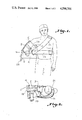
- FIG. 1 is a front elevation illustrating an abduction support constructed in accordance with the present invention in position for carrying the arm in a substantially 45 degree position with respect to the body of the patient,
- FIG. 2 is a top plan view further illustrating arrangement of FIG. 1,
- FIG. 3 is a front elevation illustrating the abduction support positioning the arm of the patient at approximately 90 degrees
- FIG. 4 is an enlarged perspective view illustrating an abduction support constructed in accordance with the present invention with strapping and attachments therefore,
- FIG. 5 is a perspective view illustrating the abduction support construction in accordance with the present invention looking toward the free end
- FIG. 6 is a perspective view illustrating strapping for attaching the arm with respect to the abduction pillow.
- FIG. 1 illustrates a shoulder abduction splint for supporting the arm of an orthopedic patient constructed from a unitary block of synthetic foam material.
- a first surface A extends substantially horizontally outwardly from an end portion of an upright support surface C carried against the body of the patient for supporting the upper arm at approximately a 90 degree angle with the body.
- a second surface B extends outwardly from the other end portion of the upright support surface toward the first surface at an angle for supporting the upper arm at approximately 45 degrees.
- a free upright surface D opposite the upright support surface is of sufficient depth to afford a thickness of foam to support the forearm and hand of the user adjacent either the first or second surfaces.
- a foam portion entends along the second surface acting in compression to support the arm when the block is turned so that the first surface supports the arm and acting in tension when said block is turned so that the second surface supports the arm.
- the block is wedge-shaped having front and rear surfaces diverging outward toward the free upright surface D to provide a support surface for the forearm and hand of the patient.
- the arm may be selectively supported in a desired position elected following shoulder surgery.
- Flat foam straps E are provided for securing said block in position with the upright support surfaces against the body with either first or second support surface uppermost as desired. Such straps are also provided for securing the forearm to the support surface.
- This second surface B has an arm rest portion extending outwardly therefrom and is illustrated as a concave arcuate portion.
- the block may be constructed of polyurethane foam or any foam providing the desirable characteristics of compressibility and flexibility.
- the surface A is generally flat and is provided with diverging sides 10 and 11 which extend outwardly form the upright surface C.
- the surface A terminates in an upturned flange 12.
- the surface A carries transversely spaced Velcro patches 13 and 14 to facilitate the attachment of flat foam strap means for securing the patient's arm to the surface A.
- the surface B is best shown in FIG. 4 and includes an outwardly extending portion tapering downwardly at substantially a 45 degree angle from a curved body portion 15.
- An outwardly extending arm rest portion 16 extends outwardly from the surface B and extends upwardly to form a flange 17.
- Upturned flanges 12 and 17 provide a check against outward movement of a patient's elbow to generally apply pressure illustrated respectively in FIGS. 3 and 1 to generally push inwardly at the elbow of the patient along the upper arm to thereby reduce tension on the shoulder joint of the patient.
- the block has an opening 22 for positioning a flat strap 24 which is provided with opposed Velcro patches 25 for securing the strap 24 about the shoulders of the patient.
- Another strap 26 is looped through the opening 22 and is provided with Velcro patches 27 for sewing the strap 26 about the waist of the patient.
- the strapping means E are provided in the form of flat strips 28 and 29 which are arranged in a substantially T-shaped configuration and sewn together as at 30. Also sewn as at 30 is a loop 31 of foam strapping provided with Velcro fastening members 32 for securing the loop 31 about the upper arm of the wearer as illustrated in FIGS. 1, 2 and 3.
- the free ends of the members 28 and 29 are provided with Velcro fastening means 33 for securement to the foam block as described above.
- a versatile abduction pillow has been provided affording opposite arm rest surfaces such that a unitary block is provided to afford support in one position while the foam adjacent the other surface acts as a structural support for the arm rest portion being used.
Abstract
Description
Claims (6)
Priority Applications (1)
| Application Number | Priority Date | Filing Date | Title |
|---|---|---|---|
| US06/609,457 US4598701A (en) | 1984-05-11 | 1984-05-11 | Shoulder abduction splint |
Applications Claiming Priority (1)
| Application Number | Priority Date | Filing Date | Title |
|---|---|---|---|
| US06/609,457 US4598701A (en) | 1984-05-11 | 1984-05-11 | Shoulder abduction splint |
Publications (1)
| Publication Number | Publication Date |
|---|---|
| US4598701A true US4598701A (en) | 1986-07-08 |
Family
ID=24440879
Family Applications (1)
| Application Number | Title | Priority Date | Filing Date |
|---|---|---|---|
| US06/609,457 Expired - Lifetime US4598701A (en) | 1984-05-11 | 1984-05-11 | Shoulder abduction splint |
Country Status (1)
| Country | Link |
|---|---|
| US (1) | US4598701A (en) |
Cited By (45)
| Publication number | Priority date | Publication date | Assignee | Title |
|---|---|---|---|---|
| EP0362528A1 (en) * | 1988-08-18 | 1990-04-11 | GMT Gesellschaft für medizinische Technik mbH | Abduction pillow |
| US5235975A (en) * | 1992-01-13 | 1993-08-17 | Pressure Products Medical Supplies, Inc. | Cardiac pacemaker compression harness |
| DE9314053U1 (en) * | 1993-09-17 | 1994-03-03 | Gmt Medizinische Technik Gmbh | Support cushion |
| US5430901A (en) * | 1993-06-10 | 1995-07-11 | Farley; David L. | Anatomically conformable therapeutic mattress overlay |
| US5464383A (en) * | 1994-08-02 | 1995-11-07 | Padden; John | Device for supporting and immobilizing a patient's arm and shoulder and method therefor |
| US5538015A (en) * | 1995-01-19 | 1996-07-23 | Paulson; John C. | Shoulder motion controlling harness |
| US5569172A (en) * | 1994-08-02 | 1996-10-29 | Padden; John | Device for supporting and immobilizing a patient's arm and shoulder and method thereof |
| DE29614223U1 (en) * | 1996-08-16 | 1996-11-14 | Sana Vita Ohg Friedl & Schmid | Arm support pillow |
| USD381543S (en) * | 1994-10-27 | 1997-07-29 | Farley David L | Foam pad |
| EP0904752A1 (en) * | 1997-09-30 | 1999-03-31 | Habermeyer, Peter, Prof. Dr. med. | Bandage system |
| FR2771625A1 (en) * | 1997-09-30 | 1999-06-04 | Kinwork | Modular harness for upper limb |
| US6003179A (en) * | 1997-11-18 | 1999-12-21 | Farley; David L. | Inclined anatomic support surface |
| US6659971B2 (en) * | 2002-03-27 | 2003-12-09 | Medical Specialties, Inc. | Shoulder abduction sling |
| US20040129278A1 (en) * | 2003-01-08 | 2004-07-08 | A.T. Labo, Co., Ltd | Shoulder dislocation acute-phase immobilization orthosis |
| US20050010147A1 (en) * | 2003-09-15 | 2005-01-13 | Dj Orthopedics, Llc | Shoulder sling |
| JP2005245611A (en) * | 2004-03-02 | 2005-09-15 | Eiji Itoi | Shoulder joint fixing orthosis |
| US20050251076A1 (en) * | 2004-04-09 | 2005-11-10 | Branch Thomas P | Method and apparatus for multidirectional positioning of a shoulder |
| US20050273026A1 (en) * | 2004-06-04 | 2005-12-08 | Howard Mark E | Shoulder stabilizing restraint |
| JP2006034307A (en) * | 2004-07-22 | 2006-02-09 | Sunao Igarashi | Health tool for shoulders |
| US20060112489A1 (en) * | 2004-04-30 | 2006-06-01 | Bobey John A | Patient support |
| US7334275B1 (en) * | 2004-09-28 | 2008-02-26 | Susan Kirkwood | Mobility assistance device |
| US20090000625A1 (en) * | 2007-06-29 | 2009-01-01 | Alfery David D | Patient Arm Pad |
| US20090250073A1 (en) * | 2007-06-29 | 2009-10-08 | Mizuho Osi | Patient Arm Pad with Adjustment |
| ITRN20090038A1 (en) * | 2009-08-17 | 2009-11-16 | Riccardo Montani | SUPPORT FOR REHABILITATION THERAPIES |
| US20100152635A1 (en) * | 2008-12-15 | 2010-06-17 | Borden Peter S | Magnetic arm sling |
| US20110155148A1 (en) * | 2009-11-18 | 2011-06-30 | Cradle Medical, Inc. | Shoulder immobilizer and fracture stabilization device |
| US8286285B2 (en) | 2009-09-21 | 2012-10-16 | Mahler Sheila J | Orthopedic support pillow |
| US8414512B2 (en) | 2011-02-11 | 2013-04-09 | Breg, Inc. | Shoulder orthosis having a supportive strapping system |
| US8523795B2 (en) | 2010-12-10 | 2013-09-03 | Top Shelf Manufacturing, Llc | Arm sling with backpack straps |
| US20130317401A1 (en) * | 2012-05-24 | 2013-11-28 | Fancastic Products, Inc. | Shoulder abduction sling-pillow-immobilizer system |
| US20140330182A1 (en) * | 2012-05-04 | 2014-11-06 | Bryan E. Kilbey | Modular Shoulder External Rotation Wedge System and Method |
| US20150173936A1 (en) * | 2013-12-19 | 2015-06-25 | Richard M. Lowden | Upper extremity immobilizer |
| US9204989B2 (en) | 2013-09-06 | 2015-12-08 | Universite De Montreal | Dynamic shoulder orthosis with rehabilitating adduction |
| US9326906B2 (en) | 2012-11-29 | 2016-05-03 | Edwinia Thanas | Therapeutic pillow |
| USD799708S1 (en) | 2015-09-11 | 2017-10-10 | Xtreme Orthopedics Llc | Shin splint with calf support brace |
| USD799709S1 (en) | 2015-09-11 | 2017-10-10 | Xtreme Orthopedics Llc | Support brace |
| USD800326S1 (en) | 2015-09-11 | 2017-10-17 | Xtreme Orthopedics Llc | Support brace |
| USD800323S1 (en) | 2015-09-11 | 2017-10-17 | Xtreme Orthopedics Llc | Compression sleeve |
| USD800325S1 (en) | 2015-09-11 | 2017-10-17 | Xtreme Orthopedics Llc | Triceps support with elbow compression sleeve |
| USD800324S1 (en) | 2015-09-11 | 2017-10-17 | Xtreme Orthopedics Llc | Knee compression sleeve |
| US10231882B2 (en) | 2013-09-10 | 2019-03-19 | Xtreme Orthopedics Llc | Device and method for applying pressure to a mammalian limb |
| US10398585B2 (en) | 2013-05-30 | 2019-09-03 | Xtreme Orthopedics Llc | Shoulder and arm restraint |
| USD962450S1 (en) | 2013-05-30 | 2022-08-30 | Extreme Orthopedics Llc | Shoulder immobilizer pillow |
| US11638656B2 (en) | 2012-12-31 | 2023-05-02 | Xtreme Orthopedics Llc | Shoulder and arm restraint |
| US11963900B2 (en) | 2023-05-02 | 2024-04-23 | Xtreme Orthopedics Llc | Shoulder and arm restraint |
Citations (5)
| Publication number | Priority date | Publication date | Assignee | Title |
|---|---|---|---|---|
| US3284817A (en) * | 1963-10-01 | 1966-11-15 | Landwirth Charles | Therapeutic cushion |
| DE2744518A1 (en) * | 1976-10-04 | 1978-04-06 | Trelleborgs Gummifabriks Ab | Inflatable flexible support pad for raised arm - has sheet of material with straps for clamping arm |
| US4241731A (en) * | 1978-05-11 | 1980-12-30 | Pauley James H | Universal arm support |
| US4270235A (en) * | 1978-11-08 | 1981-06-02 | Gutmann Gordon L | Arm support pillow |
| US4392489A (en) * | 1981-07-15 | 1983-07-12 | Bio Clinic Company | Abduction pillow |
-
1984
- 1984-05-11 US US06/609,457 patent/US4598701A/en not_active Expired - Lifetime
Patent Citations (5)
| Publication number | Priority date | Publication date | Assignee | Title |
|---|---|---|---|---|
| US3284817A (en) * | 1963-10-01 | 1966-11-15 | Landwirth Charles | Therapeutic cushion |
| DE2744518A1 (en) * | 1976-10-04 | 1978-04-06 | Trelleborgs Gummifabriks Ab | Inflatable flexible support pad for raised arm - has sheet of material with straps for clamping arm |
| US4241731A (en) * | 1978-05-11 | 1980-12-30 | Pauley James H | Universal arm support |
| US4270235A (en) * | 1978-11-08 | 1981-06-02 | Gutmann Gordon L | Arm support pillow |
| US4392489A (en) * | 1981-07-15 | 1983-07-12 | Bio Clinic Company | Abduction pillow |
Non-Patent Citations (2)
| Title |
|---|
| Flyer entitled "Application Instructions for Shoulder Abduction Support" (one pg.) by Orthopedic Equipment Co., Bourbon, Indiana, Form No. 606, Oct. 1977. |
| Flyer entitled Application Instructions for Shoulder Abduction Support (one pg.) by Orthopedic Equipment Co., Bourbon, Indiana, Form No. 606, Oct. 1977. * |
Cited By (64)
| Publication number | Priority date | Publication date | Assignee | Title |
|---|---|---|---|---|
| EP0362528A1 (en) * | 1988-08-18 | 1990-04-11 | GMT Gesellschaft für medizinische Technik mbH | Abduction pillow |
| US5235975A (en) * | 1992-01-13 | 1993-08-17 | Pressure Products Medical Supplies, Inc. | Cardiac pacemaker compression harness |
| US5430901A (en) * | 1993-06-10 | 1995-07-11 | Farley; David L. | Anatomically conformable therapeutic mattress overlay |
| DE9314053U1 (en) * | 1993-09-17 | 1994-03-03 | Gmt Medizinische Technik Gmbh | Support cushion |
| US5464383A (en) * | 1994-08-02 | 1995-11-07 | Padden; John | Device for supporting and immobilizing a patient's arm and shoulder and method therefor |
| US5569172A (en) * | 1994-08-02 | 1996-10-29 | Padden; John | Device for supporting and immobilizing a patient's arm and shoulder and method thereof |
| USD381543S (en) * | 1994-10-27 | 1997-07-29 | Farley David L | Foam pad |
| US5538015A (en) * | 1995-01-19 | 1996-07-23 | Paulson; John C. | Shoulder motion controlling harness |
| DE19735411B4 (en) * | 1996-08-16 | 2005-08-25 | Sana Plast Gmbh | Arm support cushion for hanging and wearing at the waist |
| DE29614223U1 (en) * | 1996-08-16 | 1996-11-14 | Sana Vita Ohg Friedl & Schmid | Arm support pillow |
| FR2771625A1 (en) * | 1997-09-30 | 1999-06-04 | Kinwork | Modular harness for upper limb |
| EP0904752A1 (en) * | 1997-09-30 | 1999-03-31 | Habermeyer, Peter, Prof. Dr. med. | Bandage system |
| US6003179A (en) * | 1997-11-18 | 1999-12-21 | Farley; David L. | Inclined anatomic support surface |
| US6659971B2 (en) * | 2002-03-27 | 2003-12-09 | Medical Specialties, Inc. | Shoulder abduction sling |
| US20040129278A1 (en) * | 2003-01-08 | 2004-07-08 | A.T. Labo, Co., Ltd | Shoulder dislocation acute-phase immobilization orthosis |
| EP1437110A1 (en) * | 2003-01-08 | 2004-07-14 | Itoi, Eiji, c/o Akita University School of Medicine | Shoulder immobilization device |
| US6932781B2 (en) * | 2003-01-08 | 2005-08-23 | A.T. Labo, Co., Ltd | Shoulder dislocation acute-phase immobilization orthosis |
| US20050010147A1 (en) * | 2003-09-15 | 2005-01-13 | Dj Orthopedics, Llc | Shoulder sling |
| US7563236B2 (en) | 2003-09-15 | 2009-07-21 | Djo, Llc | Shoulder sling with support pillow and pouch |
| JP2005245611A (en) * | 2004-03-02 | 2005-09-15 | Eiji Itoi | Shoulder joint fixing orthosis |
| JP4566582B2 (en) * | 2004-03-02 | 2010-10-20 | 栄二 井樋 | Shoulder joint orthosis |
| US20050251076A1 (en) * | 2004-04-09 | 2005-11-10 | Branch Thomas P | Method and apparatus for multidirectional positioning of a shoulder |
| US7686775B2 (en) | 2004-04-09 | 2010-03-30 | Branch Thomas P | Method and apparatus for multidirectional positioning of a shoulder |
| US7698765B2 (en) | 2004-04-30 | 2010-04-20 | Hill-Rom Services, Inc. | Patient support |
| US8146191B2 (en) | 2004-04-30 | 2012-04-03 | Hill-Rom Services, Inc. | Patient support |
| US20060112489A1 (en) * | 2004-04-30 | 2006-06-01 | Bobey John A | Patient support |
| US20050273026A1 (en) * | 2004-06-04 | 2005-12-08 | Howard Mark E | Shoulder stabilizing restraint |
| US7244239B2 (en) | 2004-06-04 | 2007-07-17 | Breg, Inc. | Shoulder stabilizing restraint |
| JP2006034307A (en) * | 2004-07-22 | 2006-02-09 | Sunao Igarashi | Health tool for shoulders |
| US7334275B1 (en) * | 2004-09-28 | 2008-02-26 | Susan Kirkwood | Mobility assistance device |
| US20090250073A1 (en) * | 2007-06-29 | 2009-10-08 | Mizuho Osi | Patient Arm Pad with Adjustment |
| US20090000625A1 (en) * | 2007-06-29 | 2009-01-01 | Alfery David D | Patient Arm Pad |
| WO2009006269A1 (en) * | 2007-06-29 | 2009-01-08 | David D Alfery | Patient arm pad |
| US20100152635A1 (en) * | 2008-12-15 | 2010-06-17 | Borden Peter S | Magnetic arm sling |
| ITRN20090038A1 (en) * | 2009-08-17 | 2009-11-16 | Riccardo Montani | SUPPORT FOR REHABILITATION THERAPIES |
| US8286285B2 (en) | 2009-09-21 | 2012-10-16 | Mahler Sheila J | Orthopedic support pillow |
| US8109273B2 (en) | 2009-11-18 | 2012-02-07 | Cradle Medical, Inc. | Shoulder immobilizer and fracture stabilization device |
| US10918513B2 (en) | 2009-11-18 | 2021-02-16 | Djo, Llc | Shoulder immobilizer and fracture stabilization device |
| US20110155148A1 (en) * | 2009-11-18 | 2011-06-30 | Cradle Medical, Inc. | Shoulder immobilizer and fracture stabilization device |
| US9492303B2 (en) | 2009-11-18 | 2016-11-15 | Djo, Llc | Shoulder immobilizer and fracture stabilization device |
| US8523795B2 (en) | 2010-12-10 | 2013-09-03 | Top Shelf Manufacturing, Llc | Arm sling with backpack straps |
| US8414512B2 (en) | 2011-02-11 | 2013-04-09 | Breg, Inc. | Shoulder orthosis having a supportive strapping system |
| US8992451B2 (en) | 2011-02-11 | 2015-03-31 | Breg, Inc. | Shoulder orthosis having a supportive strapping system |
| US20140330182A1 (en) * | 2012-05-04 | 2014-11-06 | Bryan E. Kilbey | Modular Shoulder External Rotation Wedge System and Method |
| US9498369B2 (en) * | 2012-05-04 | 2016-11-22 | Bryan E. Kilbey | Modular shoulder external rotation wedge system and method |
| US20130317401A1 (en) * | 2012-05-24 | 2013-11-28 | Fancastic Products, Inc. | Shoulder abduction sling-pillow-immobilizer system |
| US9326906B2 (en) | 2012-11-29 | 2016-05-03 | Edwinia Thanas | Therapeutic pillow |
| US11638656B2 (en) | 2012-12-31 | 2023-05-02 | Xtreme Orthopedics Llc | Shoulder and arm restraint |
| US11179265B2 (en) | 2012-12-31 | 2021-11-23 | Xtreme Orthopedics Llc | Shoulder and arm restraint |
| USD962450S1 (en) | 2013-05-30 | 2022-08-30 | Extreme Orthopedics Llc | Shoulder immobilizer pillow |
| US10398585B2 (en) | 2013-05-30 | 2019-09-03 | Xtreme Orthopedics Llc | Shoulder and arm restraint |
| US9204989B2 (en) | 2013-09-06 | 2015-12-08 | Universite De Montreal | Dynamic shoulder orthosis with rehabilitating adduction |
| US10231882B2 (en) | 2013-09-10 | 2019-03-19 | Xtreme Orthopedics Llc | Device and method for applying pressure to a mammalian limb |
| US11590031B2 (en) | 2013-09-10 | 2023-02-28 | Xtreme Orthopedics Llp | Device and method for applying pressure to a mammalian limb |
| US20150173936A1 (en) * | 2013-12-19 | 2015-06-25 | Richard M. Lowden | Upper extremity immobilizer |
| USD800325S1 (en) | 2015-09-11 | 2017-10-17 | Xtreme Orthopedics Llc | Triceps support with elbow compression sleeve |
| USD800324S1 (en) | 2015-09-11 | 2017-10-17 | Xtreme Orthopedics Llc | Knee compression sleeve |
| USD800323S1 (en) | 2015-09-11 | 2017-10-17 | Xtreme Orthopedics Llc | Compression sleeve |
| USD874660S1 (en) | 2015-09-11 | 2020-02-04 | Xtreme Orthopedics Llc | Shin splint with calf support brace |
| USD885588S1 (en) | 2015-09-11 | 2020-05-26 | Xtreme Orthopedics Llc | Compression sleeve |
| USD800326S1 (en) | 2015-09-11 | 2017-10-17 | Xtreme Orthopedics Llc | Support brace |
| USD799709S1 (en) | 2015-09-11 | 2017-10-10 | Xtreme Orthopedics Llc | Support brace |
| USD799708S1 (en) | 2015-09-11 | 2017-10-10 | Xtreme Orthopedics Llc | Shin splint with calf support brace |
| US11963900B2 (en) | 2023-05-02 | 2024-04-23 | Xtreme Orthopedics Llc | Shoulder and arm restraint |
Similar Documents
| Publication | Publication Date | Title |
|---|---|---|
| US4598701A (en) | Shoulder abduction splint | |
| US4640269A (en) | Back brace having strap with widened middle portion for pad | |
| US3888244A (en) | Means for supporting a limb in relaxed position | |
| US4896660A (en) | Arm elevator support device | |
| US5782785A (en) | Knee brace | |
| US4188944A (en) | Acromio-clavicular restoration brace | |
| US4751923A (en) | Sling, shoulder immobilizer and posture corrector | |
| US4446858A (en) | Arm and shoulder brace | |
| US4794916A (en) | Lumbar stabilizer | |
| US4041940A (en) | Contoured knee immobilizer | |
| US7309304B2 (en) | Adjustable back support device | |
| US4177806A (en) | Knee pillow | |
| US4550724A (en) | Orthopedic vest for support and restrainment in the treatment of subjects to trauma and surgery of the shoulder, scapular arch and upper limb | |
| US5466214A (en) | Dynamic harness for human spine | |
| US6464656B1 (en) | Dynamic arm sling | |
| US4702233A (en) | Ventilated neck brace and related structures | |
| US5515867A (en) | Head support for shoulder surgery positioner | |
| US4836195A (en) | Device for abduction of upper limbs | |
| US6730053B1 (en) | Wrist bandage | |
| JPH01268552A (en) | Collar for fixing neck | |
| US4601285A (en) | Arm sling device | |
| US8689799B2 (en) | Reversible orthosis | |
| US6110133A (en) | Convertible acromioclavicular stabilizer | |
| US6146346A (en) | Sports brace | |
| US4373517A (en) | Orthopedic arm and shoulder brace |
Legal Events
| Date | Code | Title | Description |
|---|---|---|---|
| AS | Assignment |
Owner name: SPAN-AMERICAN MEDICAL SYSTEMS, INC., P.O. BOX 6783 Free format text: ASSIGNMENT OF ASSIGNORS INTEREST.;ASSIGNOR:SCHAEFER, DANIEL J.;REEL/FRAME:004259/0873 Effective date: 19840509 Owner name: SPAN-AMERICAN MEDICAL SYSTEMS, INC., A SC CORP., S Free format text: ASSIGNMENT OF ASSIGNORS INTEREST;ASSIGNOR:SCHAEFER, DANIEL J.;REEL/FRAME:004259/0873 Effective date: 19840509 |
|
| STCF | Information on status: patent grant |
Free format text: PATENTED CASE |
|
| FEPP | Fee payment procedure |
Free format text: PAYOR NUMBER ASSIGNED (ORIGINAL EVENT CODE: ASPN); ENTITY STATUS OF PATENT OWNER: SMALL ENTITY |
|
| FPAY | Fee payment |
Year of fee payment: 4 |
|
| FPAY | Fee payment |
Year of fee payment: 8 |
|
| FPAY | Fee payment |
Year of fee payment: 12 |