US4589437A - Reel speed valve assembly - Google Patents
Reel speed valve assembly Download PDFInfo
- Publication number
- US4589437A US4589437A US06/568,582 US56858284A US4589437A US 4589437 A US4589437 A US 4589437A US 56858284 A US56858284 A US 56858284A US 4589437 A US4589437 A US 4589437A
- Authority
- US
- United States
- Prior art keywords
- valve
- assembly
- spool
- port
- compensator
- Prior art date
- Legal status (The legal status is an assumption and is not a legal conclusion. Google has not performed a legal analysis and makes no representation as to the accuracy of the status listed.)
- Expired - Fee Related
Links
Images


Classifications
-
- F—MECHANICAL ENGINEERING; LIGHTING; HEATING; WEAPONS; BLASTING
- F15—FLUID-PRESSURE ACTUATORS; HYDRAULICS OR PNEUMATICS IN GENERAL
- F15B—SYSTEMS ACTING BY MEANS OF FLUIDS IN GENERAL; FLUID-PRESSURE ACTUATORS, e.g. SERVOMOTORS; DETAILS OF FLUID-PRESSURE SYSTEMS, NOT OTHERWISE PROVIDED FOR
- F15B13/00—Details of servomotor systems ; Valves for servomotor systems
- F15B13/02—Fluid distribution or supply devices characterised by their adaptation to the control of servomotors
- F15B13/04—Fluid distribution or supply devices characterised by their adaptation to the control of servomotors for use with a single servomotor
- F15B13/0416—Fluid distribution or supply devices characterised by their adaptation to the control of servomotors for use with a single servomotor with means or adapted for load sensing
- F15B13/0417—Load sensing elements; Internal fluid connections therefor; Anti-saturation or pressure-compensation valves
-
- F—MECHANICAL ENGINEERING; LIGHTING; HEATING; WEAPONS; BLASTING
- F15—FLUID-PRESSURE ACTUATORS; HYDRAULICS OR PNEUMATICS IN GENERAL
- F15B—SYSTEMS ACTING BY MEANS OF FLUIDS IN GENERAL; FLUID-PRESSURE ACTUATORS, e.g. SERVOMOTORS; DETAILS OF FLUID-PRESSURE SYSTEMS, NOT OTHERWISE PROVIDED FOR
- F15B13/00—Details of servomotor systems ; Valves for servomotor systems
- F15B13/02—Fluid distribution or supply devices characterised by their adaptation to the control of servomotors
- F15B13/04—Fluid distribution or supply devices characterised by their adaptation to the control of servomotors for use with a single servomotor
- F15B13/0401—Valve members; Fluid interconnections therefor
- F15B13/0402—Valve members; Fluid interconnections therefor for linearly sliding valves, e.g. spool valves
-
- Y—GENERAL TAGGING OF NEW TECHNOLOGICAL DEVELOPMENTS; GENERAL TAGGING OF CROSS-SECTIONAL TECHNOLOGIES SPANNING OVER SEVERAL SECTIONS OF THE IPC; TECHNICAL SUBJECTS COVERED BY FORMER USPC CROSS-REFERENCE ART COLLECTIONS [XRACs] AND DIGESTS
- Y10—TECHNICAL SUBJECTS COVERED BY FORMER USPC
- Y10T—TECHNICAL SUBJECTS COVERED BY FORMER US CLASSIFICATION
- Y10T137/00—Fluid handling
- Y10T137/2496—Self-proportioning or correlating systems
- Y10T137/2559—Self-controlled branched flow systems
- Y10T137/2574—Bypass or relief controlled by main line fluid condition
- Y10T137/2579—Flow rate responsive
-
- Y—GENERAL TAGGING OF NEW TECHNOLOGICAL DEVELOPMENTS; GENERAL TAGGING OF CROSS-SECTIONAL TECHNOLOGIES SPANNING OVER SEVERAL SECTIONS OF THE IPC; TECHNICAL SUBJECTS COVERED BY FORMER USPC CROSS-REFERENCE ART COLLECTIONS [XRACs] AND DIGESTS
- Y10—TECHNICAL SUBJECTS COVERED BY FORMER USPC
- Y10T—TECHNICAL SUBJECTS COVERED BY FORMER US CLASSIFICATION
- Y10T137/00—Fluid handling
- Y10T137/8593—Systems
- Y10T137/86493—Multi-way valve unit
- Y10T137/86574—Supply and exhaust
- Y10T137/86582—Pilot-actuated
- Y10T137/86606—Common to plural valve motor chambers
-
- Y—GENERAL TAGGING OF NEW TECHNOLOGICAL DEVELOPMENTS; GENERAL TAGGING OF CROSS-SECTIONAL TECHNOLOGIES SPANNING OVER SEVERAL SECTIONS OF THE IPC; TECHNICAL SUBJECTS COVERED BY FORMER USPC CROSS-REFERENCE ART COLLECTIONS [XRACs] AND DIGESTS
- Y10—TECHNICAL SUBJECTS COVERED BY FORMER USPC
- Y10T—TECHNICAL SUBJECTS COVERED BY FORMER US CLASSIFICATION
- Y10T137/00—Fluid handling
- Y10T137/8593—Systems
- Y10T137/86493—Multi-way valve unit
- Y10T137/86574—Supply and exhaust
- Y10T137/86582—Pilot-actuated
- Y10T137/86614—Electric
-
- Y—GENERAL TAGGING OF NEW TECHNOLOGICAL DEVELOPMENTS; GENERAL TAGGING OF CROSS-SECTIONAL TECHNOLOGIES SPANNING OVER SEVERAL SECTIONS OF THE IPC; TECHNICAL SUBJECTS COVERED BY FORMER USPC CROSS-REFERENCE ART COLLECTIONS [XRACs] AND DIGESTS
- Y10—TECHNICAL SUBJECTS COVERED BY FORMER USPC
- Y10T—TECHNICAL SUBJECTS COVERED BY FORMER US CLASSIFICATION
- Y10T137/00—Fluid handling
- Y10T137/8593—Systems
- Y10T137/87169—Supply and exhaust
- Y10T137/87177—With bypass
- Y10T137/87185—Controlled by supply or exhaust valve
Definitions
- This invention is in the field of control valve assemblies for regulating the speed of harvester or combine reels.
- Compensated valves for the control of farm equipment machinery are well known in the prior art.
- proportional pressure compensated valves for the control of combine reel speed are generally known.
- Such valves are typically of either the open or closed center type and are also typically manufactured for a particular mounting configuration (discreet, top of stack, middle of stack, bottom of stack).
- reel speed control valves typically contain relief valves, manual control valves, and/or pressure or load sense valve assemblies.
- a valve for regulating hydraulic flow to a combine reel motor is taught in U.S. Pat. No. 3,979,908 to Alderson. This spool-type valve directs a priority flow to the reel motors of a combine while providing flow to a secondary load if possible.
- the priority flow valve of this patent is useable in either an open-center or closed-center system.
- Yet another object of the present invention is to provide a reel speed valve assembly which is controlled by a digital stepper motor or similar proportional drive.
- Still another object of the present invention is to provide a reel speed valve assembly which is capable of functioning in either an open or closed center mode.
- the reel speed valve assembly of the present invention incorporates within a single housing, a double acting compensator valve, a manually adjustable controller valve, a proportional controller valve, a relief check valve and a pressure or load sense valve.
- the proportional control valve may be of the "spool within a spool" servo-follower proportional valve type.
- Manual control valves, relief check valves, and pressure or load sense valves are optional and may be included within the unitary housing if desired.
- the reel speed valve assembly of the present invention provides proportional controller flow which is compensated to allow constant flow volume under varying conditions of pressure and flow.
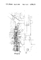
- FIG. 1 shows a cross-section of the reel speed valve assembly of the present invention.
- FIG. 2 is a cross-section of the proportional controller valve of the present invention.
- FIG. 2a shows an alternate linear actuator for the proportional controller valve of the present invention
- FIG. 2b shows another alternate linear actuator for the proporrional controller valve of the present invention.
- FIG. 2c shows yet another linear actuator for the proportional controller valve of the present invention using a normally-open pilot valve.
- FIG. 3 is a cross-section of the double acting compensator valve of the present invention.
- FIG. 4 is a cross-section of the manual bypass valve of the present invention.
- FIG. 5 is a cross-section of the relief check valve of the present invention.
- FIG. 6 is a cross-section of the pressure or load sense valve of the present invention.
- FIGS. 7 through 14 are block schematic diagrams of the operational modes of the reel speed valve assembly of the present invention.
- FIG. 1 there is shown a reel speed valve assembly comprising a compensator valve 600, a control valve 700, a manual bypass valve 800, a relief valve 900, and an output pressure (load) sense ball check valve 950.
- a source of hydraulic pressure such as a pump (not shown) is connected to the reel speed valve assembly at pressure inlet port 500.
- Low pressure return flow to a tank (not shown) exits the valve assembly at outlet port 400. Controlled flow exits the valve assembly via outlet port 300, while bypass flow exits via outlet port 200.
- control valve 700 shown in more detail in FIG. 2, there is shown a servo-follower proportional control spool valve generally described in parent application Ser. No. 511,576, now abandoned, which compprises a housing 15 having a cylindrical bore 15a for receiving a main spool 12.
- the main spool has an open bore 12a for slidably receiving a pilot spool 11.
- Valve 700 is coupled to a source of hydraulic pressure (not shown) via inlet passage 32.
- Main spool 12 has upper cylindrical land 100 and lower cylindrical land 104 spaced axially with respect to the longitudinal axis of main spool 12.
- a transverse inlet metering orifice 42 extends between cylindrical bore 15a and bore 12a in the main spool 12.
- Upper land 100 extends into a reduced diameter cylindrical section 72 which defines the top end of main spool 12 while lower land 104 extends into reduced diameter cylindrical section 73 which defines the bottom end of main spool 12.
- Connecting passages 46 and 47 are formed transverse of the longitudinal axis of main spool 12 and provide connecting passages between bore 12a and chambers formed by the outer surfaces of sections 46 and 47 respectively.
- Lands 100 and 104 on main spool 12 are slidably but sealingly received in cylindrical bore 15a.
- This bore presents a cylindrical land surface 31 disposed between annular recesses 32a and passage 47.
- Land 104 has metering V-groove 104a formed thereon
- bore 15a forms an elongated end recess 74 for receiving land 67 and a floating annular spacer 50 which abuts an end wall of end cap 78.
- Spacer 50 has its inner cylindrically-shaped bore surface 50d ground to receive the outer surface of section 72.
- a slot is formed on the outer surface of spacer 50 to provide for an O-ring 50a for sealing engagement between the spacer and recess 74. It is in this manner that spacer 50 is effective to "float" within recess 74 and the recess is referenced to tank by way of a return passage 40 and tank port 18.
- a floating ring 51 is disposed about land 68 of pilot spool 11. It will be understood that these lower end components are substantially identical to analogous structures of the upper end components and need not be described in similar detail.
- a groove 45 is formed on land 104 and communicates with outlet port 29 and a passage 43 with mian spool 12 in its illustrated full up or valve closed position. Passage 43 extends to return passage 40 so that with spool 12 in its valve closed state, outlet port 29 is in communication with tank port 18.
- pilot spool 11 is received within bore 12a of spool 12.
- Spool 11 has at its center a V-groove piston 14 defined by a pair of metering lands 14a and 14b, where the v-groove 14c is formed between the lands.
- V-shaped groove 14c is in communication with metering orifice 42.
- Metering lands 14a and 14b each form a sharp metering edge with a respective wall of orifice 42 and sealingly engage bore 12a so that there is no flow of fluid from orifice 42 into the left or right side of bore 12a.
- Spool 11 also has two axially spaced cylindrical lands 11c and 11d formed at the upper and lower ends of the spool to sealingly engage the upper and lower ends of open bore 12a in all positions of spool 11.
- Metering land 14a and land 11c are integrally interconnected by stem portion 11a which defines an elongated longitudinally directed annulus forming a longitudinal passage which extends almost one-half of the length of spool 11.
- stem portion 11b interconnects a metering land 14b and land 11d with an elongated longitudinal annulus forming a passage extending almost half the length of spool 11.
- Passage 11a leads through to passage 46 and to bleed groove 70a formed on the inner surface of bore 12a, while passage 11b leads through to bleed groove 71a also formed on the inner surface of bore 12a, and to passage 47.
- an actuator 23 which is rigidly connected as shown through the center of top portion 11c to the top section of spool 11. Actuator 23 extends through chamber 74 and through the axis of end stop 78 in sealing relation thereto.
- spools 11 and 12 are in their center position within bore 15a and the spools are in their null position with respect to each other.
- main spool 12 is at a valve closed position in bore 15a with land 104 sealingly engaging the radius of bore 15a. Accordingly, in this neutral position of main spool 12 in bore 15a, there is no flow of fluid from the inlet passage 32 to outlet passage 29. With spools 11 and 12 at null there is no flow of fluid from passage 32 through metering orifice 42 to either of chambers 20 or 21.
- Bleed grooves 70a and 71a, formed on the inner surfaces of bore 12a provide a path for fluid flow between passages 20 and 21 and tank. These bleed grooves are alternately opened and closed by motion of inner spool end portions 11c and 11d.
- compensator valve 600 is comprised of housing 15 having cylindrical bore 600a having four annular recesses 602, 604, 608 and 609. Annular recesses 602, 604, 608 and 609 are in communication with respective ports 29, 610, 620 and 630.
- a source of hydraulic pressure such as a pump (not shown) is connected to inlet port 500.
- compensator spool 650 Located within cylindrical bore 600a is compensator spool 650 having at its upper end, metering land 650a and at its lower end, cylindrical stop 650b. Spool 650 is biased into an upward position by biasing spring 600b. Land 650a has U-grooves 650n and 650m on metering edges 650x and 650y respectively, for metering flow against metering grooves 600c and 600d respectively.
- Cylindrical bore 600a is further comprised of metering grooves 600c and 600d.
- Metering groove 600c coacts with metering edge 650x of cylindrical land 650a and U-groove 650n to meter fluid flow from inlet port 500 to bypass port 200.
- Metering groove 600d coacts with metering edge 650y of cylindrical land 650a and U-groove 650m to meter flow from passage 29 to controlled flow port 300.
- pressure at inlet port 500 acts on the top of spool 650 to compress biasing spring 600b. Hydraulic fluid then flows out of compensator 600 via outlet port 610. Controlled flow of hydraulic fluid from control valve 700 enters compensator 600 at passage 29 and flows therefrom into annular recess 609. Pressure in annular recess 608 and bore 600b acts against metering edge 650y at the bottom of land 650a to urge spool 650 upward.
- Manual bypass valve 800 shown in FIG. 4 is comprised of a housing 15 having a bore 801 with an inlet port 610, outlet port 32a, and controlled flow port 820.
- a source of hydraulic pressure connected to compensator port 500 and exiting compensator 600 via port 610 flows through bore 801 and exits bore 801 via line 32a. Additionally, a portion of this flow may be directed into line 820 by opening bypass valve 800.
- Bypass valve 800 is comprised of valve seat 810 formed at the lower end of bore 801, valve body 860 mounted within bore 801 and protruding therefrom, lock nut 870, valve stem 840, set screw 850, and valve plug 830.
- Valve plug 830 is adapted to engage valve seat 810 in sealing relationship.
- Valve 800 may be adjusted to regulate fluid flow from bore 801 into line 820 by adjustment of lead screw 850. Upward adjustment of lead screw 850 causes concomitant upward motion of valve stem 840, and permits fluid flow into line 820.
- bypass valve 800 may be accomplished by any suitable known valve device.
- Reflief valve 900 shown in FIG. 5, provides a path for diverting excessive pressure to tank.
- the relief valve is comprised of housing 15 having a bore 901. Bore 901 communicates at its upper end with channel 32b which in turn communicates at its upper end with channel 32a. Formed at the junction of channel 32b and bore 901 is valve seat 904.
- Relief valve 900 is preferably of the check valve type. Situated within bore 901 are valve plug 910 having on its lower end plug stem 930, biasing spring 920 for biasing valve plug 910 into sealing relationship against valve seat 904, and adjustable stop 934 having on its upper surface stop stem 932. Biasing spring 920 is positioned in surrounding relationship to plug stem 930 at its upper end and to stop stem 932 at its lower end.
- Adjustable stop 934 is connected at its lower surface to adjustment stem 945 which is slidably retained within collar 946 and sealed by O-ring 947. Stem 945 is moved along its longitudinal axis by adjustment of adjusting screw 940.
- adjustment of adjusting screw 940 effects an essentially linear adjustment of the pressure at which check valve 900 will open to permit flow therethrough.
- Pressure sense valve 950 shown in FIG. 6, is comprised of housing 15 having bore 951 which communicates at its upper end with channel 960 which in turn is in communication with channel 29a. Located within bore 951 are ball stop 990, biasing spring 980, and ball 970. Valve seat 965 is formed at the junction of bore 951 and channel 960.
- Ball stop 990 has at its upper end a reduced diameter stem 991. Ball stop 990 further has at its lower end, retaining plug 995.
- biasing spring 980 biases ball 970 into sealing relationship with valve seat 965 to prevent reverse flow into bore 960 from 953.
- Biasing spring 980 is situated in surrounding relationship to stem 992 and bears against the upper surface of ball stop 990.
- Bore 951 is in communication with channel 953 which terminates at port 953a which may be connected to suitable pressure or flow monitoring means, or a load sense pump.
- valve assembly of the present invention uses a solid spool control valve instead of the previously described servofollower control valve 700.
- a spool having the same external configuration as previously described and shown in FIGS. 1 and 2 is controlled by linear actuators other than a digital motor.
- a first alternative embodiment as shown in FIG. 2a uses a manually adjustable lead-screw 100' to position the control valve spool 12' and thus set the controlled flow rate.
- spool 12' is biased into an upward, valve-closed position by a coil spring 101 located at the lower end of the spool.
- FIG. 2b depicts yet another linear actuator for use within the valve assembly of the present invention.
- Actuator 100" comprises a small cylinder and piston assembly 105. This assembly may be actuated by a source of fluid pressure applied to port 107.
- Assembly 105 is comprised of bore 105c within which is mounted piston 105a.
- the upper face of piston 105a is exposed within chamber 105b and is acted on by fluid pressure therein.
- Chamber 105b is fed by orifice 107a which in turn communicates with port 107.
- linear actuator which may be employed for the purposes of the present invention is a proportional solenoid or normally-open pilot as shown in FIG. 2c.
- a feedback transducer such as a linear variable displacement transformer or other transducer as, for instance, the Licon Series 33 of Ceramic Magnetics, Inc. may also be used to sense spool position and thus permit more precise adjustments in flow rate.
- the valve assembly of the present invention is supplied a source of hydraulic flow by connection to a pump (not shown) at pressure inlet port 500.
- the primary fluid path through the valve assembly for controlled flow enters the assembly at port 500 and exits the compensator assembly via line 610.
- Line 610 connects to inlet passage 32 of the controller valve 700 which allows flow through annular recess 32a to outlet passage 29.
- Outlet passage 29 traverses the valve assembly and communicates with annular recess 609 of compensator 600.
- Annular recess 609 in turn communicates with bore 600a and in turn with annular recess 608 and controlled flow port 300 which exits the valve assembly.
- An alternative controlled flow path diverges from the path just described at the junction of bore 801 with passage 610. Flow enters bore 801 which further communicates with bore 820. Bore 820 is also in communication with channel 29 which is in turn in communication with annular recess 608 of compensator 600 and outlet port 300.
- Bypass flows are metered by compensator spool 650 at its metering edge 650x and U-groove 650n and allowed to flow across metering edge 600c to annular recess 604.
- Annular recess 604 is in communication with bypass flow port 200 which exits the valve assembly.
- FIGS. 7 through 14 there are shown block diagrams of the present invention which describe the paths available for fluid flow and positions of the flow controlling elements.
- FIG. 7 the flow through the valve assembly of the present invention is shown when the controller spool 12 entirely prevents flow through the controller valve 700.
- pressure is exerted on the compensator spool in a downward direction permitting the entire flow to exit the valve assembly via the bypass port 200.
- FIG. 8 details the operation of the valve assembly when the controller spool 62 allows fluid flow across the metering V-groove control orifice on its lower land.
- the metered control flow acts against the lower metering edge of the compensator spool 650 forcing it upward in opposition to the force exerted by the incoming flow from the pressure source 500.
- the compensator acts to maintain constant pressure differential across the controller spool control orifice.
- An increase in pressure or in flow rate is compensated by a re-equilibration of the spool position within the compensator.
- the controller 700 is shown in its fully open position. Again, the compensator spool 650 attains an equilibrium position in response to pressure and volume flow changes so as to provide constant control flow volume by metering bypass flow.
- FIG. 10 details the operation of the valve assembly of the present invention when a manually operated control valve is installed.
- the manually operated control valve 800 provides a variable orifice permitting fluid flow between the inlet of the controller valve and the outlet passage of the controller.
- the manual control valve When opened, provides a constant flow rate proportional to its orifice size through the controlled flow port 800. As shown in FIG. 10, this flow is the only control flow due to the controller spool 12 being in the closed position.
- valve assembly of the present invention comprising a pressure relief check valve 900.
- the valve assembly is operated as an open center valve. Pressure build-up which does not exceed the pressure necessary to open the relief check valve flows via the compensator to bypass flow port 200.
- FIG. 12 details the operation of the present valve assembly when pressure within the valve exceeds that required to actuate the relief check valve 900. Flow within the valve is diverted across the check valve orifice to tank 400.
- FIG. 13 illustrates the operation of the valve assembly of the present invention as a closed center valve. It will be appreciated by those skilled in the art that any of the foregoing modes of operation may be analogously carried out as closed center operations by the insertion of a plug or similar flow restriction in the bypass port.
- the compensator spool 650 When operated as a closed center valve assembly, the compensator spool 650 continues to regulate flow through the control flow port 300 by attaining an equilibrium position to meter that flow.
- FIG. 14 illustrates the operation of the valve assembly of the present invention as a closed center valve having a pressure or load sense valve. Load may be sensed as a function of pressure of fluid in line 29 by a suitable ball check valve feeding a load sense port. Known load sense apparatus may be connected to the load sense port for operation in this mode.
- Enhancements to the present valve as detailed in FIGS. 7 through 14, including manual control valves, load sense valves, and relief check valves, may be provided for operation in the closed center mode.
- the relief check valve detailed in FIGS. 11 and 12 may be particularly desireable when operating the present valve assembly in a closed center mode.
Abstract
Description
Claims (8)
Priority Applications (1)
| Application Number | Priority Date | Filing Date | Title |
|---|---|---|---|
| US06/568,582 US4589437A (en) | 1983-07-07 | 1984-01-06 | Reel speed valve assembly |
Applications Claiming Priority (2)
| Application Number | Priority Date | Filing Date | Title |
|---|---|---|---|
| US51157683A | 1983-07-07 | 1983-07-07 | |
| US06/568,582 US4589437A (en) | 1983-07-07 | 1984-01-06 | Reel speed valve assembly |
Related Parent Applications (1)
| Application Number | Title | Priority Date | Filing Date |
|---|---|---|---|
| US51157683A Continuation-In-Part | 1983-07-07 | 1983-07-07 |
Publications (1)
| Publication Number | Publication Date |
|---|---|
| US4589437A true US4589437A (en) | 1986-05-20 |
Family
ID=27057270
Family Applications (1)
| Application Number | Title | Priority Date | Filing Date |
|---|---|---|---|
| US06/568,582 Expired - Fee Related US4589437A (en) | 1983-07-07 | 1984-01-06 | Reel speed valve assembly |
Country Status (1)
| Country | Link |
|---|---|
| US (1) | US4589437A (en) |
Cited By (12)
| Publication number | Priority date | Publication date | Assignee | Title |
|---|---|---|---|---|
| US5245827A (en) * | 1992-08-03 | 1993-09-21 | Deere & Company | Supply valve arrangement for closed center hydraulic system |
| US5351601A (en) * | 1992-05-04 | 1994-10-04 | Control Concepts, Inc. | Hydraulic control system |
| US5442992A (en) * | 1993-08-20 | 1995-08-22 | Greenlee Textron Inc. | Hydraulic control apparatus with selectively operated check valve assembly |
| US5778755A (en) * | 1996-03-01 | 1998-07-14 | Greenlee Textron Inc. | Control valve having a sensor switchable between an open and a closed condition |
| US6116263A (en) * | 1998-07-23 | 2000-09-12 | Hydraforce, Inc. | Proportional priority flow regulator with reverse flow control |
| US6490962B1 (en) | 2001-05-17 | 2002-12-10 | The Stanley Works | Hydraulic tool with an OC/CC selector |
| US20030047222A1 (en) * | 2001-09-12 | 2003-03-13 | Neff James A. | Pilot operated pneumatic valve |
| US6772791B2 (en) | 2002-05-17 | 2004-08-10 | Mac Valves, Inc. | Directly operated pneumatic valve having an air assist return |
| US20050005672A1 (en) * | 2001-12-11 | 2005-01-13 | Sneath Michael Stuart | Hydraulic crimping apparatus |
| US20050016375A1 (en) * | 2003-07-25 | 2005-01-27 | Julie Harwath | Mechanism for switching between closed and open center hydraulic systems |
| US11137084B2 (en) * | 2019-04-11 | 2021-10-05 | Ningxia Danchen Technology Co., LTD | Solenoid valve for activity test of extraction check valve |
| US11162612B2 (en) * | 2019-04-11 | 2021-11-02 | Ningxia Danchen Technology Co., LTD | Device for activity test of extraction check valve |
Citations (12)
| Publication number | Priority date | Publication date | Assignee | Title |
|---|---|---|---|---|
| US26338A (en) * | 1859-12-06 | Improvement in harvesters | ||
| US2600348A (en) * | 1949-12-30 | 1952-06-10 | Gen Electric | Two-stage hydraulic control valve |
| US3381936A (en) * | 1965-02-18 | 1968-05-07 | Fawick Corp | Hydraulic system and remotely operated flow control arrangement therein |
| US3532104A (en) * | 1968-01-24 | 1970-10-06 | Kenneth H Hoen | Pressure compensated flow control valve system |
| US3596677A (en) * | 1969-01-13 | 1971-08-03 | Rex Chainbelt Inc | Remotely operable pressure compensated flow control valve |
| US3628557A (en) * | 1969-08-15 | 1971-12-21 | Cessna Aircraft Co | Variable preferential flow control valve |
| US3785392A (en) * | 1971-10-21 | 1974-01-15 | Eaton Corp | Flow control valve |
| DE2445053A1 (en) * | 1974-09-20 | 1976-04-01 | Liebherr Aera Technik Gmbh | Control for proportioning regulating valves - has electromagnetic valve slide with circumferential control edge to divide slide bore |
| DE2506864A1 (en) * | 1975-02-18 | 1976-08-26 | Schneider Co Optische Werke | DIRECTIONAL VALVE |
| US4121610A (en) * | 1976-02-02 | 1978-10-24 | Ambac Industries Incorporated | Electrically operated proportional flow control hydraulic valve and manually operable remote control device therefor |
| US4430846A (en) * | 1982-01-15 | 1984-02-14 | Electro-Hydraulic Controls, Inc. | Electrohydraulic drive and control |
| US4462566A (en) * | 1982-02-08 | 1984-07-31 | French Bruce C | Pressure compensated flow control system |
-
1984
- 1984-01-06 US US06/568,582 patent/US4589437A/en not_active Expired - Fee Related
Patent Citations (12)
| Publication number | Priority date | Publication date | Assignee | Title |
|---|---|---|---|---|
| US26338A (en) * | 1859-12-06 | Improvement in harvesters | ||
| US2600348A (en) * | 1949-12-30 | 1952-06-10 | Gen Electric | Two-stage hydraulic control valve |
| US3381936A (en) * | 1965-02-18 | 1968-05-07 | Fawick Corp | Hydraulic system and remotely operated flow control arrangement therein |
| US3532104A (en) * | 1968-01-24 | 1970-10-06 | Kenneth H Hoen | Pressure compensated flow control valve system |
| US3596677A (en) * | 1969-01-13 | 1971-08-03 | Rex Chainbelt Inc | Remotely operable pressure compensated flow control valve |
| US3628557A (en) * | 1969-08-15 | 1971-12-21 | Cessna Aircraft Co | Variable preferential flow control valve |
| US3785392A (en) * | 1971-10-21 | 1974-01-15 | Eaton Corp | Flow control valve |
| DE2445053A1 (en) * | 1974-09-20 | 1976-04-01 | Liebherr Aera Technik Gmbh | Control for proportioning regulating valves - has electromagnetic valve slide with circumferential control edge to divide slide bore |
| DE2506864A1 (en) * | 1975-02-18 | 1976-08-26 | Schneider Co Optische Werke | DIRECTIONAL VALVE |
| US4121610A (en) * | 1976-02-02 | 1978-10-24 | Ambac Industries Incorporated | Electrically operated proportional flow control hydraulic valve and manually operable remote control device therefor |
| US4430846A (en) * | 1982-01-15 | 1984-02-14 | Electro-Hydraulic Controls, Inc. | Electrohydraulic drive and control |
| US4462566A (en) * | 1982-02-08 | 1984-07-31 | French Bruce C | Pressure compensated flow control system |
Cited By (14)
| Publication number | Priority date | Publication date | Assignee | Title |
|---|---|---|---|---|
| US5351601A (en) * | 1992-05-04 | 1994-10-04 | Control Concepts, Inc. | Hydraulic control system |
| US5245827A (en) * | 1992-08-03 | 1993-09-21 | Deere & Company | Supply valve arrangement for closed center hydraulic system |
| US5442992A (en) * | 1993-08-20 | 1995-08-22 | Greenlee Textron Inc. | Hydraulic control apparatus with selectively operated check valve assembly |
| US5778755A (en) * | 1996-03-01 | 1998-07-14 | Greenlee Textron Inc. | Control valve having a sensor switchable between an open and a closed condition |
| US6116263A (en) * | 1998-07-23 | 2000-09-12 | Hydraforce, Inc. | Proportional priority flow regulator with reverse flow control |
| US6490962B1 (en) | 2001-05-17 | 2002-12-10 | The Stanley Works | Hydraulic tool with an OC/CC selector |
| US20030047222A1 (en) * | 2001-09-12 | 2003-03-13 | Neff James A. | Pilot operated pneumatic valve |
| US6543481B2 (en) * | 2001-09-12 | 2003-04-08 | Mac Valves, Inc. | Pilot operated pneumatic valve |
| US20050005672A1 (en) * | 2001-12-11 | 2005-01-13 | Sneath Michael Stuart | Hydraulic crimping apparatus |
| US6772791B2 (en) | 2002-05-17 | 2004-08-10 | Mac Valves, Inc. | Directly operated pneumatic valve having an air assist return |
| US20050016375A1 (en) * | 2003-07-25 | 2005-01-27 | Julie Harwath | Mechanism for switching between closed and open center hydraulic systems |
| US6990888B2 (en) | 2003-07-25 | 2006-01-31 | Greenlee Textron Inc. | Mechanism for switching between closed and open center hydraulic systems |
| US11137084B2 (en) * | 2019-04-11 | 2021-10-05 | Ningxia Danchen Technology Co., LTD | Solenoid valve for activity test of extraction check valve |
| US11162612B2 (en) * | 2019-04-11 | 2021-11-02 | Ningxia Danchen Technology Co., LTD | Device for activity test of extraction check valve |
Similar Documents
| Publication | Publication Date | Title |
|---|---|---|
| US5878647A (en) | Pilot solenoid control valve and hydraulic control system using same | |
| US3722543A (en) | Pressure compensated control valve | |
| US6073652A (en) | Pilot solenoid control valve with integral pressure sensing transducer | |
| US5890362A (en) | Hydraulic control valve system with non-shuttle pressure compensator | |
| US5791142A (en) | Hydraulic control valve system with split pressure compensator | |
| US6318079B1 (en) | Hydraulic control valve system with pressure compensated flow control | |
| US5715865A (en) | Pressure compensating hydraulic control valve system | |
| US4589437A (en) | Reel speed valve assembly | |
| US5161373A (en) | Hydraulic control valve system | |
| US5921279A (en) | Solenoid operated dual spool control valve | |
| US5056561A (en) | Remote controlled, individually pressure compensated valve | |
| EP0008523B1 (en) | Improvements relating to hydraulic control systems | |
| US3985153A (en) | Pressure compensating valve spool assembly for a hydraulic control valve | |
| EP0987444A2 (en) | Proportional priority flow regulator with reverse flow control | |
| US6038957A (en) | Control valves | |
| EP0202385A1 (en) | Reel speed valve assembly | |
| US4085920A (en) | Pilot control valve with servo means | |
| US3815622A (en) | Bidirectional differential valve | |
| US3920034A (en) | Proportional bypass valve having variable area orifice control means | |
| US4459807A (en) | Control apparatus for fluid operated systems | |
| CA1240235A (en) | Reel speed valve assembly | |
| US5876184A (en) | Electrohydraulic pressure regulating valve | |
| US4246934A (en) | Remotely controlled load responsive valves | |
| JPS58185372A (en) | Detector for liquid load | |
| US4049232A (en) | Pressure compensating fluid control valve |
Legal Events
| Date | Code | Title | Description |
|---|---|---|---|
| AS | Assignment |
Owner name: INTEGRATED TECHNOLOGIES AND SYSTEMS, INC., NEWTOWN Free format text: ASSIGNMENT OF ASSIGNORS INTEREST.;ASSIGNORS:ZEUNER, KENNETH W.;ZEUNER, STEVEN K.;ZEUNER, THOMAS A.;REEL/FRAME:004950/0505 Effective date: 19880601 Owner name: INTEGRATED TECHNOLOGIES AND SYSTEMS, INC., NEWTOWN Free format text: ASSIGNMENT OF ASSIGNORS INTEREST;ASSIGNORS:ZEUNER, KENNETH W.;ZEUNER, STEVEN K.;ZEUNER, THOMAS A.;REEL/FRAME:004950/0505 Effective date: 19880601 |
|
| FEPP | Fee payment procedure |
Free format text: PAYOR NUMBER ASSIGNED (ORIGINAL EVENT CODE: ASPN); ENTITY STATUS OF PATENT OWNER: LARGE ENTITY |
|
| AS | Assignment |
Owner name: FIRST PENNSYLVANIA BANK, N.A., A CORP. OF PA, PENN Free format text: SECURITY INTEREST;ASSIGNOR:INTEGRATED TECHNOLOGIES AND SYSTEMS, INC.;REEL/FRAME:005228/0041 Effective date: 19880923 |
|
| AS | Assignment |
Owner name: CONTROLS CONCEPTS, INC. Free format text: CHANGE OF NAME;ASSIGNOR:INTEGRATED TECHNOLOGIES AND SYSTEMS, INC.;REEL/FRAME:005164/0071 Effective date: 19890224 |
|
| FPAY | Fee payment |
Year of fee payment: 4 |
|
| AS | Assignment |
Owner name: CONTROL CONCEPTS, INC., PENNSYLVANIA Free format text: CHANGE OF NAME;ASSIGNOR:INTEGRATED TECHNOLOGIES AND SYSTEMS, INC.;REEL/FRAME:006319/0451 Effective date: 19890301 |
|
| FEPP | Fee payment procedure |
Free format text: PAT HLDR NO LONGER CLAIMS SMALL ENT STAT AS INDIV INVENTOR (ORIGINAL EVENT CODE: LSM1); ENTITY STATUS OF PATENT OWNER: LARGE ENTITY |
|
| FPAY | Fee payment |
Year of fee payment: 8 |
|
| AS | Assignment |
Owner name: CONTROL CONCEPTS, INC., PENNSYLVANIA Free format text: RELEASE OF SECURITY INTEREST AND REASSIGNMENT OF ALL RIGHTS, TITLE AND INTEREST;ASSIGNOR:CORESTATES BANK, N.A.;REEL/FRAME:006920/0001 Effective date: 19940315 |
|
| REMI | Maintenance fee reminder mailed | ||
| LAPS | Lapse for failure to pay maintenance fees | ||
| FP | Lapsed due to failure to pay maintenance fee |
Effective date: 19980520 |
|
| STCH | Information on status: patent discontinuation |
Free format text: PATENT EXPIRED DUE TO NONPAYMENT OF MAINTENANCE FEES UNDER 37 CFR 1.362 |