US4585323A - Corona generating device - Google Patents
Corona generating device Download PDFInfo
- Publication number
- US4585323A US4585323A US06/680,867 US68086784A US4585323A US 4585323 A US4585323 A US 4585323A US 68086784 A US68086784 A US 68086784A US 4585323 A US4585323 A US 4585323A
- Authority
- US
- United States
- Prior art keywords
- corona
- generating device
- shield
- corona generating
- paint
- Prior art date
- Legal status (The legal status is an assumption and is not a legal conclusion. Google has not performed a legal analysis and makes no representation as to the accuracy of the status listed.)
- Expired - Lifetime
Links
- MWUXSHHQAYIFBG-UHFFFAOYSA-N Nitric oxide Chemical compound O=[N] MWUXSHHQAYIFBG-UHFFFAOYSA-N 0.000 claims abstract description 111
- 239000003973 paint Substances 0.000 claims abstract description 47
- PXHVJJICTQNCMI-UHFFFAOYSA-N Nickel Chemical compound [Ni] PXHVJJICTQNCMI-UHFFFAOYSA-N 0.000 claims abstract description 34
- 239000002923 metal particle Substances 0.000 claims abstract description 19
- 229910052759 nickel Inorganic materials 0.000 claims abstract description 17
- 239000000758 substrate Substances 0.000 claims abstract description 13
- 239000003989 dielectric material Substances 0.000 claims abstract description 12
- 229910052751 metal Inorganic materials 0.000 claims abstract description 11
- 239000002184 metal Substances 0.000 claims abstract description 11
- 238000003384 imaging method Methods 0.000 claims abstract description 9
- 150000002500 ions Chemical class 0.000 claims abstract description 9
- 239000011133 lead Substances 0.000 claims abstract description 6
- RYGMFSIKBFXOCR-UHFFFAOYSA-N Copper Chemical compound [Cu] RYGMFSIKBFXOCR-UHFFFAOYSA-N 0.000 claims abstract description 4
- 239000010949 copper Substances 0.000 claims abstract description 4
- 229910052802 copper Inorganic materials 0.000 claims abstract description 4
- 238000000151 deposition Methods 0.000 claims abstract description 4
- BQCADISMDOOEFD-UHFFFAOYSA-N Silver Chemical compound [Ag] BQCADISMDOOEFD-UHFFFAOYSA-N 0.000 claims abstract description 3
- HCHKCACWOHOZIP-UHFFFAOYSA-N Zinc Chemical compound [Zn] HCHKCACWOHOZIP-UHFFFAOYSA-N 0.000 claims abstract description 3
- 239000000203 mixture Substances 0.000 claims abstract description 3
- 229910052709 silver Inorganic materials 0.000 claims abstract description 3
- 239000004332 silver Substances 0.000 claims abstract description 3
- 229910052725 zinc Inorganic materials 0.000 claims abstract description 3
- 239000011701 zinc Substances 0.000 claims abstract description 3
- 239000011521 glass Substances 0.000 claims description 7
- JOYRKODLDBILNP-UHFFFAOYSA-N urethane group Chemical group NC(=O)OCC JOYRKODLDBILNP-UHFFFAOYSA-N 0.000 claims description 4
- NIXOWILDQLNWCW-UHFFFAOYSA-N acrylic acid group Chemical group C(C=C)(=O)O NIXOWILDQLNWCW-UHFFFAOYSA-N 0.000 claims description 3
- 239000004593 Epoxy Substances 0.000 claims description 2
- 241000894007 species Species 0.000 claims 6
- 241000149947 Coronarchaica corona Species 0.000 claims 1
- PCHJSUWPFVWCPO-UHFFFAOYSA-N gold Chemical compound [Au] PCHJSUWPFVWCPO-UHFFFAOYSA-N 0.000 abstract description 8
- 229910052737 gold Inorganic materials 0.000 abstract description 8
- 239000010931 gold Substances 0.000 abstract description 8
- 108091008695 photoreceptors Proteins 0.000 description 28
- 239000010410 layer Substances 0.000 description 27
- 229910052782 aluminium Inorganic materials 0.000 description 12
- XAGFODPZIPBFFR-UHFFFAOYSA-N aluminium Chemical compound [Al] XAGFODPZIPBFFR-UHFFFAOYSA-N 0.000 description 12
- 238000000576 coating method Methods 0.000 description 12
- 239000011248 coating agent Substances 0.000 description 11
- 238000012217 deletion Methods 0.000 description 9
- 230000037430 deletion Effects 0.000 description 9
- 239000002245 particle Substances 0.000 description 8
- 230000007547 defect Effects 0.000 description 7
- 238000006243 chemical reaction Methods 0.000 description 5
- 239000000463 material Substances 0.000 description 5
- 229910001960 metal nitrate Inorganic materials 0.000 description 5
- 238000000034 method Methods 0.000 description 5
- 238000012360 testing method Methods 0.000 description 4
- XLYOFNOQVPJJNP-UHFFFAOYSA-N water Substances O XLYOFNOQVPJJNP-UHFFFAOYSA-N 0.000 description 4
- BUGBHKTXTAQXES-UHFFFAOYSA-N Selenium Chemical class [Se] BUGBHKTXTAQXES-UHFFFAOYSA-N 0.000 description 3
- 230000008901 benefit Effects 0.000 description 3
- 230000000694 effects Effects 0.000 description 3
- 230000002427 irreversible effect Effects 0.000 description 3
- 230000007246 mechanism Effects 0.000 description 3
- KBJMLQFLOWQJNF-UHFFFAOYSA-N nickel(ii) nitrate Chemical compound [Ni+2].[O-][N+]([O-])=O.[O-][N+]([O-])=O KBJMLQFLOWQJNF-UHFFFAOYSA-N 0.000 description 3
- 150000002823 nitrates Chemical class 0.000 description 3
- 239000004417 polycarbonate Substances 0.000 description 3
- 229920000515 polycarbonate Polymers 0.000 description 3
- 238000005507 spraying Methods 0.000 description 3
- CBENFWSGALASAD-UHFFFAOYSA-N Ozone Chemical compound [O-][O+]=O CBENFWSGALASAD-UHFFFAOYSA-N 0.000 description 2
- MCMNRKCIXSYSNV-UHFFFAOYSA-N Zirconium dioxide Chemical compound O=[Zr]=O MCMNRKCIXSYSNV-UHFFFAOYSA-N 0.000 description 2
- 239000010953 base metal Substances 0.000 description 2
- 230000001680 brushing effect Effects 0.000 description 2
- 230000015556 catabolic process Effects 0.000 description 2
- 238000004140 cleaning Methods 0.000 description 2
- 230000001627 detrimental effect Effects 0.000 description 2
- 238000007598 dipping method Methods 0.000 description 2
- RLJMLMKIBZAXJO-UHFFFAOYSA-N lead nitrate Chemical compound [O-][N+](=O)O[Pb]O[N+]([O-])=O RLJMLMKIBZAXJO-UHFFFAOYSA-N 0.000 description 2
- 150000002739 metals Chemical class 0.000 description 2
- 238000012986 modification Methods 0.000 description 2
- 230000004048 modification Effects 0.000 description 2
- 230000003472 neutralizing effect Effects 0.000 description 2
- 239000004033 plastic Substances 0.000 description 2
- 229920003023 plastic Polymers 0.000 description 2
- 238000007747 plating Methods 0.000 description 2
- BASFCYQUMIYNBI-UHFFFAOYSA-N platinum Chemical compound [Pt] BASFCYQUMIYNBI-UHFFFAOYSA-N 0.000 description 2
- 239000011148 porous material Substances 0.000 description 2
- 239000000843 powder Substances 0.000 description 2
- 230000008569 process Effects 0.000 description 2
- 230000002035 prolonged effect Effects 0.000 description 2
- 230000002441 reversible effect Effects 0.000 description 2
- 150000003839 salts Chemical class 0.000 description 2
- 229910052711 selenium Inorganic materials 0.000 description 2
- 239000011669 selenium Substances 0.000 description 2
- 238000001179 sorption measurement Methods 0.000 description 2
- 239000000126 substance Substances 0.000 description 2
- 238000012546 transfer Methods 0.000 description 2
- FRWYFWZENXDZMU-UHFFFAOYSA-N 2-iodoquinoline Chemical compound C1=CC=CC2=NC(I)=CC=C21 FRWYFWZENXDZMU-UHFFFAOYSA-N 0.000 description 1
- 229910052582 BN Inorganic materials 0.000 description 1
- PZNSFCLAULLKQX-UHFFFAOYSA-N Boron nitride Chemical compound N#B PZNSFCLAULLKQX-UHFFFAOYSA-N 0.000 description 1
- LFQSCWFLJHTTHZ-UHFFFAOYSA-N Ethanol Chemical compound CCO LFQSCWFLJHTTHZ-UHFFFAOYSA-N 0.000 description 1
- 229910001370 Se alloy Inorganic materials 0.000 description 1
- 229910052581 Si3N4 Inorganic materials 0.000 description 1
- 239000012790 adhesive layer Substances 0.000 description 1
- 229910045601 alloy Inorganic materials 0.000 description 1
- 239000000956 alloy Substances 0.000 description 1
- PNEYBMLMFCGWSK-UHFFFAOYSA-N aluminium oxide Inorganic materials [O-2].[O-2].[O-2].[Al+3].[Al+3] PNEYBMLMFCGWSK-UHFFFAOYSA-N 0.000 description 1
- 230000000712 assembly Effects 0.000 description 1
- 238000000429 assembly Methods 0.000 description 1
- LTPBRCUWZOMYOC-UHFFFAOYSA-N beryllium oxide Inorganic materials O=[Be] LTPBRCUWZOMYOC-UHFFFAOYSA-N 0.000 description 1
- 239000006229 carbon black Substances 0.000 description 1
- 229920006217 cellulose acetate butyrate Polymers 0.000 description 1
- 229910010293 ceramic material Inorganic materials 0.000 description 1
- 230000000052 comparative effect Effects 0.000 description 1
- 239000004020 conductor Substances 0.000 description 1
- 238000011109 contamination Methods 0.000 description 1
- 230000008878 coupling Effects 0.000 description 1
- 238000010168 coupling process Methods 0.000 description 1
- 238000005859 coupling reaction Methods 0.000 description 1
- 230000003111 delayed effect Effects 0.000 description 1
- 230000008021 deposition Effects 0.000 description 1
- 238000011161 development Methods 0.000 description 1
- 238000006073 displacement reaction Methods 0.000 description 1
- 238000001035 drying Methods 0.000 description 1
- 238000002474 experimental method Methods 0.000 description 1
- 238000010438 heat treatment Methods 0.000 description 1
- 230000003993 interaction Effects 0.000 description 1
- 230000000670 limiting effect Effects 0.000 description 1
- 238000012423 maintenance Methods 0.000 description 1
- 238000004519 manufacturing process Methods 0.000 description 1
- 238000000465 moulding Methods 0.000 description 1
- 238000006386 neutralization reaction Methods 0.000 description 1
- 239000003921 oil Substances 0.000 description 1
- 239000012466 permeate Substances 0.000 description 1
- 229910052697 platinum Inorganic materials 0.000 description 1
- 230000001681 protective effect Effects 0.000 description 1
- 239000011241 protective layer Substances 0.000 description 1
- 230000002829 reductive effect Effects 0.000 description 1
- 230000001105 regulatory effect Effects 0.000 description 1
- 238000011160 research Methods 0.000 description 1
- 239000011347 resin Substances 0.000 description 1
- 229920005989 resin Polymers 0.000 description 1
- HQVNEWCFYHHQES-UHFFFAOYSA-N silicon nitride Chemical compound N12[Si]34N5[Si]62N3[Si]51N64 HQVNEWCFYHHQES-UHFFFAOYSA-N 0.000 description 1
- 239000007787 solid Substances 0.000 description 1
- 239000002904 solvent Substances 0.000 description 1
- 239000007921 spray Substances 0.000 description 1
- 230000007480 spreading Effects 0.000 description 1
- 238000003892 spreading Methods 0.000 description 1
- 229910001220 stainless steel Inorganic materials 0.000 description 1
- 239000010935 stainless steel Substances 0.000 description 1
- WFKWXMTUELFFGS-UHFFFAOYSA-N tungsten Chemical compound [W] WFKWXMTUELFFGS-UHFFFAOYSA-N 0.000 description 1
- 229910052721 tungsten Inorganic materials 0.000 description 1
- 239000010937 tungsten Substances 0.000 description 1
- 238000001771 vacuum deposition Methods 0.000 description 1
- 230000000007 visual effect Effects 0.000 description 1
- 238000005406 washing Methods 0.000 description 1
Images


Classifications
-
- G—PHYSICS
- G03—PHOTOGRAPHY; CINEMATOGRAPHY; ANALOGOUS TECHNIQUES USING WAVES OTHER THAN OPTICAL WAVES; ELECTROGRAPHY; HOLOGRAPHY
- G03G—ELECTROGRAPHY; ELECTROPHOTOGRAPHY; MAGNETOGRAPHY
- G03G15/00—Apparatus for electrographic processes using a charge pattern
- G03G15/02—Apparatus for electrographic processes using a charge pattern for laying down a uniform charge, e.g. for sensitising; Corona discharge devices
- G03G15/0258—Apparatus for electrographic processes using a charge pattern for laying down a uniform charge, e.g. for sensitising; Corona discharge devices provided with means for the maintenance of the charging apparatus, e.g. cleaning devices, ozone removing devices G03G15/0225, G03G15/0291 takes precedence
-
- G—PHYSICS
- G03—PHOTOGRAPHY; CINEMATOGRAPHY; ANALOGOUS TECHNIQUES USING WAVES OTHER THAN OPTICAL WAVES; ELECTROGRAPHY; HOLOGRAPHY
- G03G—ELECTROGRAPHY; ELECTROPHOTOGRAPHY; MAGNETOGRAPHY
- G03G15/00—Apparatus for electrographic processes using a charge pattern
- G03G15/02—Apparatus for electrographic processes using a charge pattern for laying down a uniform charge, e.g. for sensitising; Corona discharge devices
- G03G15/0291—Apparatus for electrographic processes using a charge pattern for laying down a uniform charge, e.g. for sensitising; Corona discharge devices corona discharge devices, e.g. wires, pointed electrodes, means for cleaning the corona discharge device
-
- H—ELECTRICITY
- H01—ELECTRIC ELEMENTS
- H01T—SPARK GAPS; OVERVOLTAGE ARRESTERS USING SPARK GAPS; SPARKING PLUGS; CORONA DEVICES; GENERATING IONS TO BE INTRODUCED INTO NON-ENCLOSED GASES
- H01T19/00—Devices providing for corona discharge
-
- Y—GENERAL TAGGING OF NEW TECHNOLOGICAL DEVELOPMENTS; GENERAL TAGGING OF CROSS-SECTIONAL TECHNOLOGIES SPANNING OVER SEVERAL SECTIONS OF THE IPC; TECHNICAL SUBJECTS COVERED BY FORMER USPC CROSS-REFERENCE ART COLLECTIONS [XRACs] AND DIGESTS
- Y10—TECHNICAL SUBJECTS COVERED BY FORMER USPC
- Y10S—TECHNICAL SUBJECTS COVERED BY FORMER USPC CROSS-REFERENCE ART COLLECTIONS [XRACs] AND DIGESTS
- Y10S430/00—Radiation imagery chemistry: process, composition, or product thereof
- Y10S430/001—Electric or magnetic imagery, e.g., xerography, electrography, magnetography, etc. Process, composition, or product
- Y10S430/102—Electrically charging radiation-conductive surface
Definitions
- the present invention relates generally to charging devices and in particular to charging devices which produce a negative corona.
- a photoconductive insulating member may be charged to a negative potential, thereafter exposed to a light image of an original document to be reproduced.
- the exposure discharges the photoconductive insulating surface in exposed or background areas and creates an electrostatic latent image on the member which corresponds to the image areas contained within the original document.
- the electrostatic latent image on the photoconductive insulating surface is made visible by developing the image with a developing powder referred to in the art as toner.
- toner particles are attracted from the carrier particles by the charge pattern of the image areas on the photoconductive insulating area to form a powder image on the photoconductive area.
- This image may be subsequently transferred to a support surface such as copy paper to which it may be permanently affixed by heating or by the application of pressure.
- a support surface such as copy paper to which it may be permanently affixed by heating or by the application of pressure.
- the photoconductive insulating surface may be discharged and cleaned of residual toner to prepare for the next imaging cycle.
- Various types of charging devices have been used to charge or precharge photoconductive insulating layers.
- corona generating devices to which a high voltage of 5,000 to 8,000 volts may be applied to the corotron device thereby producing a corona spray which imparts electrostatic charge to the surface of the photoreceptor.
- a recently developed corona charging device is described in U.S. Pat. No. 4,086,650 to Davis et al., commonly referred to in the art as a dicorotron wherein the corona discharge electrode is coated with a relatively thick dielectric material such as glass so as to substantially prevent to flow of conduction current therethrough.
- the delivery of charge to the photoconductive surface is accomplished by means of a displacement current or capacitive coupling through the dielectric material.
- the flow of charge to the surface to be charged is regulated by means of a DC bias applied to the corona shield.
- a DC bias applied to the corona shield In operation an AC potential of from about 5,000 to 7,000 volts at a frequency of about 4 KHz produces a true corona current, an ion current of 1 to 2 milliamps.
- This device has the advantage of providing a uniform negative charge to the photoreceptor.
- it is a relatively low maintenance charging device in that it is the least sensitive of the charging devices to contamination by dirt and therefore does not have to be repeatedly cleaned.
- the dielectric coated corona discharge electrode is a coated wire supported between insulating end blocks and the device has a conductive auxiliary DC electrode positioned opposite to the imaging surface on which the charge is to be placed.
- the conductive corona electrode is also in the form of an elongated wire connected to a corona generating power supply and supported by end blocks with the wire being partially surrounded by a conductive shield which is usually electrically grounded. The surface to be charged is spaced from the wire on the side opposite the shield and is mounted on a conductive substrate.
- a negative precharging is used to neutralize the positive charge remaining on the photoreceptor after transfer of the developed toner image to the copy sheet and cleaning to prepare the photoreceptor for the next copying cycle.
- a precharge corotron a AC potential of between 4,500 and 6,000 volts rms at 400 to 600 Hz may be applied.
- a typical conventional corona discharge device of this type is shown generally in U.S. Pat. No. 2,836,725 in which a conductive corona electrode in the form of an elongated wire is connected to a corona generating AC voltage.
- the air flow may direct the nitrogen oxide species to an affected area of the charging device or even some other machine part. It has also been found that after such exposure when a machine is turned off for extended periods of idleness that the adsorbed nitrogen oxide species gradually are desorbed, that is the adsorption is a physically reversible process. Then, when the operation of the machine is resumed, a copy quality defect is observed in the copies produced in that a line image deletion or lower density image is formed across the width of the photoreceptor at that portion of its surface which was at rest opposite the corona generating device during the period of idleness.
- the supporting substrate may be conductive or may be coated with a conductive layer over which photoconductive layers may be coated.
- the multilayered electroconductive imaging photoreceptor may comprise at least two electrically operative layers, a photogenerating layer or a charge generating layer and a charge transport layer which are typically applied to the conductive layer.
- a photogenerating layer or a charge generating layer and a charge transport layer which are typically applied to the conductive layer.
- U.S. Pat. No. 4,265,990 In all these varying structures several of the layers may be applied with a vacuum deposition technique for very thin layers.
- the problem is perceived after a machine has been operated for about 10,000 copies, rested overnight and when the operator activates the machine the following morning, the line deletion defect will appear.
- the defect is reversible to some degree by a rest period.
- the period involved may be of the order of several days which to an operator is objectionable.
- the gold is plated in a very thin layer and consequently the layer is discontinuous having numerous pores in the layer.
- Gold plating is theorized to provide a relatively inert surface which will not adsorb the nitrogen oxide species.
- the nickel substrate underneath the gold corrodes forming nickel nitrates in the same manner as with the precharge corotron and experiences similar difficulties resulting in limited useful life.
- a corona generating device for depositing a negative charge on an imaging surface wherein the damaging nitrogen oxide species generated by the corona charging unit and absorbed by at least one element of the corona charging device adjacent the corona discharge electrode during operation and desorbed when at rest, are neutralized.
- the element which adsorbs and desorbs the nitrogen oxide species is coated with a substantially continuous thin layer of a paint containing reactive metal particles which will combine with the nitrogen oxide species, the reactive metal being present in the paint in an amount sufficient to neutralize the nitrogen oxide species when generated.
- the element which adsorbs and desorbs the nitrogen oxide species comprises a conductive shield which substantially surrounds the corona discharge electrode and has a longitudinal opening therein to permit ions emitted from the electrode to be directed toward the surface to be charged.
- the corona discharge electrode comprises a thin wire coated at least in the discharge area with a dielectric material.
- the corona generating device comprises a planar shield and includes an insulating housing having two sides adjacent said shield to define a longitudinal opening to permit ions emitted from the electrode to be directed toward the surface to be charged.
- the two sides of the insulating housing as well as a conductive shield are coated with a substantially continuous thin layer of a paint containing reactive metal particles.
- a power supply means is supplied for applying an AC corona generating voltage to the corona discharge electrode and for providing a DC potential between the substrate to be charged and the conductive shield.
- the paint contains metal particles which may be lead, copper, nickel, silver, zinc or mixtures thereof in an amount of at least 50 percent by volume of the paint.
- the paint contains nickel particles.
- FIG. 1 is an illustrative cross section of a corona discharge device according to the present invention.
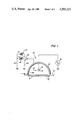
- FIG. 2 is an isometric view of a preferred embodiment of a dicorotron according to the present invention.
- FIG. 3 is an isometric view of another preferred embodiment of corotron according to the present invention.
- the corona generator 10 of this invention is seen to comprise a corona discharge electrode 11 in the form of a conductive wire 12 having a relatively thick coating 13 of dielectric material.
- a charge collecting surface 14 is shown which may be a photoconductive surface in a conventional xerographic systems.
- the charge collecting surface 14 is carried on a conductive substrate 15 held at a reference potential, usually machine ground.
- An AC voltage source 18 is connected between the substrate 15 and the corona wire 12, the magnitude of the AC source being selected to generate a corona discharge adjacent the wire 12.
- a conductive shield 20 is located adjacent the corona wire on the side of the wire opposite the chargeable surface.
- the shield 20 has coupled thereto a switch 22 which depending on its position, permits the corona device to be operated in either a charge neutralizing mode or a charge deposition mode.
- the switch 22 as shown, the shield 20 of the corona device is coupled to ground via a lead 24. In this position, no DC field is generated between the surface 14 and the shield 15 and the corona device operates to neutralize over a number of AC cycles any charge present on the surface 14.
- the shield With switch 22 in either of the positions shown by dotted lines, the shield is coupled to one terminal of a DC source 23 or 27, the other terminals of the sources being coupled by lead 26 to ground thereby establish a DC field between the surface 14 and the shield 20.
- the corona operates to deposit a net charge onto the surface 14, the polarity and magnitude of this charge depends on the polarity and magnitude of the DC bias applied to the shield 20.
- the corona wire 13 may be supported in conventional fashion at the ends thereof by insulting end blocks (not shown) mounted within the ends of shield structure 20.
- the wire 12 may be made of any conventional conductive filament material such as stainless steel, gold, aluminum, copper, tungsten, platinum or the like.
- the diameter of the wire 11 is not critical and may vary typically between 0.5-15 mil. and preferably is about 9 mils.
- any suitable dielectric material may be employed as the coating 13 which will not break down under the applied corona AC voltage, and which will withstand chemical attack under the conditions present in a corona device.
- Inorganic dielectrics have been found to perform more satisfactorily than organic dielectrics due to their higher voltage breakdown properties, and greater resistance to chemical reaction in the corona environment.
- the thickness of the dielectric coating 13 used in the corona device of the invention is such that substantially no conduction current or DC charging current is permitted therethrough.
- the thickness is such that the combined wire and dielectric thickness falls in the range from 7-30 mil with typical dielectric thickness of 2-10 mil. Glasses with dielectric breakdown strengths above 2 KV/mil at 4 Hz and in the range of 2 to 5 mil thickness have been found by experiment to perform satisfactorily as the dielectric coating material. As the frequency or thickness go down the strength in volts will usually increase.
- the glass coating selected should be free of voids and inclusions and make good contact with or wet the wire on which it is deposited.
- Other possible coatings are ceramic materials such as Alumina, Zirconia, Boron Nitride, Beryllium Oxide and Silicon Nitride. Organic dielectrics which are sufficiently stable in corona may also be used.
- the frequency of the AC source 18 may be varied widely in the range from 60 hz. commercial source to several megahertz. The device has been operated and tested at 4 KHz. and found to operate satisfactorily.
- the shield 20 is shown as being semi-circular in shape but any of the conventional shapes used for corona shields in xerographic charging may be employed.
- the function of the shield 20 may be performed by any conductive member, for example, a base wire, in the vicinity of the wire, the precise location not being critical in order to obtain satisfactory operation of the device.
- the device With the switch 22 connected as shown so that the shield 20 is grounded, the device operates to inherently neutralize any charge present on the surface 14. This is a result of the fact that no net DC charging current passes through the electrode 11 by virtue of the thick dielectric coating 13 and the wire 12.
- operation of the corona device of the invention to deposit a specific net charge on an imaging surface is accomplished by moving switch 22 to one of the positions shown in dotted lines, whereby a DC potential of either positive polarity or negative polarity with respect to the surface 15 may be applied to the shield.
- the shield 20 has a substantially continuous thin layer 28 of a paint containing a reactive metal particles which will combine with the nitrogen oxide species, the reactive metal being present in the paint in an amount sufficient to neutralize the nitrogen oxide species when they are generated.
- the exact mechanism in which the base metal containing paint neutralizes the nitrogen oxide species is not fully understood. However, it is believed that the metals combined with the nitrogen oxides forming metal nitrates in an irreversible reaction and therefore completely remove the possibility of exposure with the photoreceptor to the nitrogen oxide species.
- the nitrogen oxide species penetrate the paint film and are neutralized by the metal in the paint and since the metal nitrates thus formed are not immediately exposed to moisture in the air, the moisture has to penetrate the paint before it has any effect on it.
- lead nitrate is the only one of the metals recited which forms a non-deliquescent nitrate salt the other metal nitrates are protected from moisture by the layer of paint.
- the paint should be in the form of a substantially continuous thin layer without pores.
- the paint should be sufficiently thick that the metal particles within it will not be consumed in reasonable periods of time thereby limiting operation of the device. Accordingly, it is preferred that the thin layer of paint contain at least 50 percent by volume metal particles and be applied in thickness of about 0.5 to about 1.0 mil. Furthermore in the event that a conductive coating is desired the metal particle loading can be increased even further to provide the necessary particle to particle contact in the paint layer. In this instance metal particles may be present in an amount of up to about 60 percent by volume.
- the metal particles are dispersed within the paint vehicle which may be selected from any of those conventionally used vehicles such as the urethane, epoxy and acrylic paints. There are a number of commercially available such paints having metal particles dispersed within a resin. The paint may be applied to the surface to be neutralized through any of the conventional brushing, spraying or dipping techniques well known in the art.
- FIG. 2 illustrates a preferred embodiment in the dicorotron device according to the present invention.
- the dicorotron wire 30 is supported between anchors 31 at opposite ends which are anchored in end blocks 35.
- the conductive shield 34 is constructed in tubular fashion in such a way as to be slideably mounted in the bottom of the housing 39 by means of handle 36.
- the shield is connected to the power supply through a sliding contact in its inner surface to a leaf spring which in turn is connected to a DC pin connector (not shown).
- the power supply potential may be positive, negative, or zero (grounded) depending on device function. It is fastened in place when inserted within the housing 39 by means of spring retaining member 38. When inserted in the machine high voltage contact pin 33 provides the necessary contact to the AC power supply.
- the housing 39 comprises two vertically extending side panels 32 extending the entire length of the dicorotron wire. Both the top and inner surface of the shield 34 and the interior of the vertically extending panels 32 of the housing 39 are coated with the paint 40 according to the practice of the present invention.
- the housing 39 together with the side panels 32 may be made from a single one piece molding from any suitable material such as a glass filled polycarbonate.
- a comparative test was conducted with the device illustrated in FIG. 2.
- a dicorotron device without the paints and just employing the conductive shield made out of aluminum together with the single one piece molded housing from a glass filled polycarbonate material were used in the Xerox 1075 as a charging device for the production of about 10,000 copies.
- the machine was shut down and rested overnight and operation resumed the next morning at which time a line deletion or drop in line image density was observed across that narrow portion of the photoreceptor which was opposite the dicorotron charging device during shut down. This was as a result of lower surface charge density and a corresponding lower developed toner mass per unit area. This image deletion was repeated for each revolution of the photoreceptor.
- a strip of aluminum half of which is coated with a nickel filled paint was placed over the elongated slot of the dicorotron charging device which was activated for about 500 hours. Thereafter the aluminum strip was removed and placed adjacent to the same photoreceptor belt spaced apart by about 0.06 inches overnight. The next morning the photoreceptor was charged exposed to an image pattern with no deletion problem being experienced over that portion of the photoreceptor placed adjacent to the portion of the aluminum strip which had been coated with the nickel filled paint. However, the portion of the photoreceptor opposite the unpainted portion of the aluminum strip showed signs of the deletion problem in that the line images were blurred in that area.
- the nickel filled paint was Emilux 1832 available from General Electric Company in Schenectady, New York which is an air dry, water borne, nickel filled acrylic coating containing about 50 percent by volume, nickel particles. This was applied to the aluminum strip by first cleaning the aluminum strip to free it of contaminents such as oil and chemical deposits and drying. Thereafter the Emilux 1832 was applied by spraying.
- FIG. 3 illustrates an alternative embodiment according to the present invention and in particular is directed to a single wire corotron device wherein the wire 44 is supported between insulating end block assemblies 42 and 43.
- a conductive corotron shield 46 which is grounded increases the ion density available for conduction. Since no charge builds up on the shield the voltage between the shield and the wire remain constant and a constant density of ions is generated by the wire. The effect of the grounded shield is to increase the amount of current flowing to the plate.
- the corona wire 44 at one end is fastened to port 52 in the end block assembly and at the other end is fastened to port 50 of the second end block assembly.
- the wire 44 at the second end of the corona generating is connected to the corona potential generating source 48 by lead 55.
- Such a device might have utility as an AC precharge corona generating device, in which case the corotron shield 46 would be coated with the reactive metal filled paints according to the present invention.
- the dicorotron charging device and in particular that illustrated in FIG. 2 above, may have application, for example, as a charging device in the machine concept described and illustrated in U.S. Pat. No. 4,318,610 to Grace.
- the negative charging devices according to the present invention have the advantage of successfully neutralizing nitrogen oxides formed during the charging operation. While it is not fully understood, it is believed that the metal particles in the paint combined with the nitrogen oxide species in an irreversible reaction forming the metal nitrates. Furthermore other than the lead nitrate that may be formed, the other metal nitrates that may also be formed include deliquescent materials, nitrates of which are not immediately exposed to the surface and therefore the moisture in the air has to permeate the paint before it has an effect on it. Accordingly any visual defect in the coating is substantially reduced and certainly delayed.
- metal filled paints according to the present invention have the advantage of being commercially available in many forms and may be applied by simple brushing, spraying or dipping techniques without the use of extensive and expensive equipment.
- the paint formed on the affected surfaces maintains its physical integrity for a relatively long period of time and can be coated directly onto a plastic substrate without pretreatment or other type of protective or adhesive layer.
Abstract
Description
Claims (14)
Priority Applications (2)
| Application Number | Priority Date | Filing Date | Title |
|---|---|---|---|
| US06/680,867 US4585323A (en) | 1984-12-12 | 1984-12-12 | Corona generating device |
| JP60274287A JPS61144670A (en) | 1984-12-12 | 1985-12-05 | Corona generator |
Applications Claiming Priority (1)
| Application Number | Priority Date | Filing Date | Title |
|---|---|---|---|
| US06/680,867 US4585323A (en) | 1984-12-12 | 1984-12-12 | Corona generating device |
Publications (1)
| Publication Number | Publication Date |
|---|---|
| US4585323A true US4585323A (en) | 1986-04-29 |
Family
ID=24732851
Family Applications (1)
| Application Number | Title | Priority Date | Filing Date |
|---|---|---|---|
| US06/680,867 Expired - Lifetime US4585323A (en) | 1984-12-12 | 1984-12-12 | Corona generating device |
Country Status (2)
| Country | Link |
|---|---|
| US (1) | US4585323A (en) |
| JP (1) | JPS61144670A (en) |
Cited By (22)
| Publication number | Priority date | Publication date | Assignee | Title |
|---|---|---|---|---|
| US4780680A (en) * | 1984-11-03 | 1988-10-25 | Hoechst Aktiengesellschaft | Process for the continuous, contact-free measurement of layer thicknesses and apparatus for performing the process |
| US4792680A (en) * | 1987-01-12 | 1988-12-20 | Xerox Corporation | Corona device having a beryllium copper screen |
| US4801967A (en) * | 1987-11-23 | 1989-01-31 | Xerox Corporation | Voltage sensing in A.C. corotrons |
| US4837658A (en) * | 1988-12-14 | 1989-06-06 | Xerox Corporation | Long life corona charging device |
| US4841146A (en) * | 1987-08-03 | 1989-06-20 | Xerox Corporation | Self-cleaning scorotron with focused ion beam |
| US4853719A (en) * | 1988-12-14 | 1989-08-01 | Xerox Corporation | Coated ion projection printing head |
| US4920266A (en) * | 1989-03-27 | 1990-04-24 | Xerox Corporation | Corona generating device |
| US4956670A (en) * | 1988-08-04 | 1990-09-11 | Fuji Xerox Co., Ltd. | Electrostatic latent image forming apparatus controlling the direction of derivation of ions |
| US5132188A (en) * | 1990-08-13 | 1992-07-21 | Rca Thomson Licensing Corp. | Method for charging a concave surface of a CRT faceplate panel |
| US5257073A (en) * | 1992-07-01 | 1993-10-26 | Xerox Corporation | Corona generating device |
| EP0590840A2 (en) * | 1992-09-28 | 1994-04-06 | Xerox Corporation | Corona generating device |
| US5408911A (en) * | 1991-03-04 | 1995-04-25 | Lyrrus, Inc. | Musical instrument string |
| US5451754A (en) * | 1993-10-27 | 1995-09-19 | Xerox Corporation | Corona generating device |
| EP0684527A1 (en) | 1994-05-27 | 1995-11-29 | Xerox Corporation | Photoconductive charging processes |
| US5485253A (en) * | 1994-01-03 | 1996-01-16 | Xerox Corporation | Corona generating device having replaceable shield members |
| US5568230A (en) * | 1995-02-03 | 1996-10-22 | Xerox Corporation | Replaceable ozone absorbing substrates for a photocopying device |
| US5666601A (en) * | 1991-08-01 | 1997-09-09 | Xerox Corporation | Resistive ion source charging device |
| US5835838A (en) * | 1994-07-12 | 1998-11-10 | Xerox Corporation | Photoreceptor cleaning/contamination prevention system |
| US5907468A (en) * | 1994-10-19 | 1999-05-25 | Haug Gmbh & Co. Kg | Device for applying unipolar electrical charges to a moving electrically-insulated surface using a corona electrode |
| US20050047829A1 (en) * | 2003-08-29 | 2005-03-03 | Konica Minolta Business Technologies, Inc. | Charging device and image forming apparatus |
| US20090148186A1 (en) * | 2007-12-10 | 2009-06-11 | Ricoh Company, Ltd | Corona charger, and process cartridge and image forming apparatus using same |
| CN105339787A (en) * | 2013-06-21 | 2016-02-17 | 蒙特利尔史密斯安检仪公司 | Method and device for a coated corona ionization source |
Families Citing this family (2)
| Publication number | Priority date | Publication date | Assignee | Title |
|---|---|---|---|---|
| JPH01319062A (en) * | 1988-06-20 | 1989-12-25 | Canon Inc | Corona discharger |
| JP2008164707A (en) * | 2006-12-27 | 2008-07-17 | Toray Eng Co Ltd | Image forming apparatus and method |
Citations (8)
| Publication number | Priority date | Publication date | Assignee | Title |
|---|---|---|---|---|
| US2574225A (en) * | 1948-07-28 | 1951-11-06 | Benzol Products Company | Process for rendering metal surfaces antiseptic and products therefrom |
| US2813804A (en) * | 1952-06-13 | 1957-11-19 | Steel Ceilings Inc | Lead coating process |
| US2836725A (en) * | 1956-11-19 | 1958-05-27 | Haloid Co | Corona charging device |
| US3862420A (en) * | 1973-11-01 | 1975-01-21 | Ibm | System to prevent the formation of particulate material in corona units |
| US4086650A (en) * | 1975-07-14 | 1978-04-25 | Xerox Corporation | Corona charging device |
| US4265990A (en) * | 1977-05-04 | 1981-05-05 | Xerox Corporation | Imaging system with a diamine charge transport material in a polycarbonate resin |
| US4318610A (en) * | 1980-04-21 | 1982-03-09 | Xerox Corporation | Control system for an electrophotographic printing machine |
| US4379129A (en) * | 1976-05-06 | 1983-04-05 | Fuji Xerox Co., Ltd. | Method of decomposing ozone |
Family Cites Families (6)
| Publication number | Priority date | Publication date | Assignee | Title |
|---|---|---|---|---|
| JPS4429103Y1 (en) * | 1965-09-02 | 1969-12-02 | ||
| JPS571296B2 (en) * | 1974-01-28 | 1982-01-11 | ||
| JPS5134866A (en) * | 1974-09-19 | 1976-03-24 | Asahi Chemical Ind | HAIGASUJOKAHOHO |
| US4003475A (en) * | 1974-11-27 | 1977-01-18 | Fmc Corporation | Crane boom lattice and hoist line protection assembly |
| JPS5339965A (en) * | 1976-09-24 | 1978-04-12 | Hideo Soejima | Method of removing acidic gases from combusting gas |
| IT1115385B (en) * | 1977-08-01 | 1986-02-03 | Bramer C Henri | APPARATUS AND PROCEDURE FOR PURIFYING EXHAUST GAS |
-
1984
- 1984-12-12 US US06/680,867 patent/US4585323A/en not_active Expired - Lifetime
-
1985
- 1985-12-05 JP JP60274287A patent/JPS61144670A/en active Pending
Patent Citations (8)
| Publication number | Priority date | Publication date | Assignee | Title |
|---|---|---|---|---|
| US2574225A (en) * | 1948-07-28 | 1951-11-06 | Benzol Products Company | Process for rendering metal surfaces antiseptic and products therefrom |
| US2813804A (en) * | 1952-06-13 | 1957-11-19 | Steel Ceilings Inc | Lead coating process |
| US2836725A (en) * | 1956-11-19 | 1958-05-27 | Haloid Co | Corona charging device |
| US3862420A (en) * | 1973-11-01 | 1975-01-21 | Ibm | System to prevent the formation of particulate material in corona units |
| US4086650A (en) * | 1975-07-14 | 1978-04-25 | Xerox Corporation | Corona charging device |
| US4379129A (en) * | 1976-05-06 | 1983-04-05 | Fuji Xerox Co., Ltd. | Method of decomposing ozone |
| US4265990A (en) * | 1977-05-04 | 1981-05-05 | Xerox Corporation | Imaging system with a diamine charge transport material in a polycarbonate resin |
| US4318610A (en) * | 1980-04-21 | 1982-03-09 | Xerox Corporation | Control system for an electrophotographic printing machine |
Non-Patent Citations (6)
| Title |
|---|
| "Electroless Plating Today", Metal Finishing, pp. 45-49 and 52, Author-Edward B. Saubestre, Aug. 1962. |
| Defensive Publication T940022 Pressurized & Filtered Xerographic System Rodda. Pub. Nov. 4, 1975. * |
| Defensive Publication T940022-Pressurized & Filtered Xerographic System-Rodda.-Pub. Nov. 4, 1975. |
| Electroless Plating Today , Metal Finishing, pp. 45 49 and 52, Author Edward B. Saubestre, Aug. 1962. * |
| Research Disclosure Nov. 1980, p. 508, Item 19957, Corona Discharge Unit . * |
| Research Disclosure-Nov. 1980, p. 508, Item 19957, "Corona Discharge Unit". |
Cited By (29)
| Publication number | Priority date | Publication date | Assignee | Title |
|---|---|---|---|---|
| US4780680A (en) * | 1984-11-03 | 1988-10-25 | Hoechst Aktiengesellschaft | Process for the continuous, contact-free measurement of layer thicknesses and apparatus for performing the process |
| US4792680A (en) * | 1987-01-12 | 1988-12-20 | Xerox Corporation | Corona device having a beryllium copper screen |
| US4841146A (en) * | 1987-08-03 | 1989-06-20 | Xerox Corporation | Self-cleaning scorotron with focused ion beam |
| US4801967A (en) * | 1987-11-23 | 1989-01-31 | Xerox Corporation | Voltage sensing in A.C. corotrons |
| US4956670A (en) * | 1988-08-04 | 1990-09-11 | Fuji Xerox Co., Ltd. | Electrostatic latent image forming apparatus controlling the direction of derivation of ions |
| US4837658A (en) * | 1988-12-14 | 1989-06-06 | Xerox Corporation | Long life corona charging device |
| US4853719A (en) * | 1988-12-14 | 1989-08-01 | Xerox Corporation | Coated ion projection printing head |
| US4920266A (en) * | 1989-03-27 | 1990-04-24 | Xerox Corporation | Corona generating device |
| EP0390488A2 (en) * | 1989-03-27 | 1990-10-03 | Xerox Corporation | Corona generating device |
| EP0390488A3 (en) * | 1989-03-27 | 1991-03-20 | Xerox Corporation | Corona generating device |
| US5132188A (en) * | 1990-08-13 | 1992-07-21 | Rca Thomson Licensing Corp. | Method for charging a concave surface of a CRT faceplate panel |
| US5408911A (en) * | 1991-03-04 | 1995-04-25 | Lyrrus, Inc. | Musical instrument string |
| US5666601A (en) * | 1991-08-01 | 1997-09-09 | Xerox Corporation | Resistive ion source charging device |
| US5257073A (en) * | 1992-07-01 | 1993-10-26 | Xerox Corporation | Corona generating device |
| EP0590840A3 (en) * | 1992-09-28 | 1995-06-28 | Xerox Corp | Corona generating device. |
| EP0590840A2 (en) * | 1992-09-28 | 1994-04-06 | Xerox Corporation | Corona generating device |
| US5451754A (en) * | 1993-10-27 | 1995-09-19 | Xerox Corporation | Corona generating device |
| US5485253A (en) * | 1994-01-03 | 1996-01-16 | Xerox Corporation | Corona generating device having replaceable shield members |
| EP0684527A1 (en) | 1994-05-27 | 1995-11-29 | Xerox Corporation | Photoconductive charging processes |
| US5835838A (en) * | 1994-07-12 | 1998-11-10 | Xerox Corporation | Photoreceptor cleaning/contamination prevention system |
| US5907468A (en) * | 1994-10-19 | 1999-05-25 | Haug Gmbh & Co. Kg | Device for applying unipolar electrical charges to a moving electrically-insulated surface using a corona electrode |
| US5568230A (en) * | 1995-02-03 | 1996-10-22 | Xerox Corporation | Replaceable ozone absorbing substrates for a photocopying device |
| US20050047829A1 (en) * | 2003-08-29 | 2005-03-03 | Konica Minolta Business Technologies, Inc. | Charging device and image forming apparatus |
| US7039342B2 (en) * | 2003-08-29 | 2006-05-02 | Konica Minolta Business Technologies, Inc. | Charging device and image forming apparatus where the charging device is composed of a sufficient amount of nickel to suppress oxidation |
| US20090148186A1 (en) * | 2007-12-10 | 2009-06-11 | Ricoh Company, Ltd | Corona charger, and process cartridge and image forming apparatus using same |
| US8059992B2 (en) | 2007-12-10 | 2011-11-15 | Ricoh Company, Ltd. | Corona charger, and process cartridge and image forming apparatus using same |
| CN105339787A (en) * | 2013-06-21 | 2016-02-17 | 蒙特利尔史密斯安检仪公司 | Method and device for a coated corona ionization source |
| EP3011328A4 (en) * | 2013-06-21 | 2017-02-22 | Smiths Detection Montreal Inc. | Method and device for a coated corona ionization source |
| US9837257B2 (en) | 2013-06-21 | 2017-12-05 | Smiths Detection Montreal Inc. | Method and device for a coated corona ionization source |
Also Published As
| Publication number | Publication date |
|---|---|
| JPS61144670A (en) | 1986-07-02 |
Similar Documents
| Publication | Publication Date | Title |
|---|---|---|
| US4585323A (en) | Corona generating device | |
| US4646196A (en) | Corona generating device | |
| US4585320A (en) | Corona generating device | |
| US4585322A (en) | Corona generating device | |
| US4920266A (en) | Corona generating device | |
| US3038073A (en) | Electrostatic charging | |
| US4837658A (en) | Long life corona charging device | |
| US5469242A (en) | Corona generating device having a heated shield | |
| US5539205A (en) | Corona generating device and method of fabricating | |
| US5451754A (en) | Corona generating device | |
| JP3863222B2 (en) | Charging apparatus and electrostatographic printing apparatus | |
| US4989021A (en) | Cleaning device for conductive magnetic toner and image recording apparatus using same | |
| US5485253A (en) | Corona generating device having replaceable shield members | |
| US7050743B2 (en) | Self-regenerative xerographic coatings | |
| US7264752B2 (en) | Conductive coatings for corona generating devices | |
| JPH0823715B2 (en) | Corona generator | |
| US3612864A (en) | Imaging system utilizing an electrode treated with a mixture of a hygroscopic material and a hydrophilic binder | |
| US7295797B2 (en) | Charge generating device and method thereof for reducing development of nitrogen oxide species formation | |
| US5455660A (en) | Electrical method and apparatus to control corona effluents | |
| US5483324A (en) | Charging device for an image forming apparatus | |
| US5554469A (en) | Charging processes with liquid compositions | |
| US5781833A (en) | Sealed liquid charging apparatus | |
| US3877963A (en) | Reversal liquid developing using a development electrode and corona charging | |
| JPH01125245A (en) | Recorder | |
| JPH05134564A (en) | Image forming device |
Legal Events
| Date | Code | Title | Description |
|---|---|---|---|
| AS | Assignment |
Owner name: XEROX CORPORATION STAMFORD, CT A CORP. OF NY Free format text: ASSIGNMENT OF ASSIGNORS INTEREST.;ASSIGNORS:EWING, JOAN R.;WALLIN, EDWIN M.;REEL/FRAME:004349/0337 Effective date: 19841206 |
|
| STCF | Information on status: patent grant |
Free format text: PATENTED CASE |
|
| FPAY | Fee payment |
Year of fee payment: 4 |
|
| FPAY | Fee payment |
Year of fee payment: 8 |
|
| FPAY | Fee payment |
Year of fee payment: 12 |
|
| AS | Assignment |
Owner name: BANK ONE, NA, AS ADMINISTRATIVE AGENT, ILLINOIS Free format text: SECURITY INTEREST;ASSIGNOR:XEROX CORPORATION;REEL/FRAME:013153/0001 Effective date: 20020621 |
|
| AS | Assignment |
Owner name: JPMORGAN CHASE BANK, AS COLLATERAL AGENT, TEXAS Free format text: SECURITY AGREEMENT;ASSIGNOR:XEROX CORPORATION;REEL/FRAME:015134/0476 Effective date: 20030625 Owner name: JPMORGAN CHASE BANK, AS COLLATERAL AGENT,TEXAS Free format text: SECURITY AGREEMENT;ASSIGNOR:XEROX CORPORATION;REEL/FRAME:015134/0476 Effective date: 20030625 |
|
| AS | Assignment |
Owner name: XEROX CORPORATION, CONNECTICUT Free format text: RELEASE BY SECURED PARTY;ASSIGNOR:JPMORGAN CHASE BANK, N.A. AS SUCCESSOR-IN-INTEREST ADMINISTRATIVE AGENT AND COLLATERAL AGENT TO JPMORGAN CHASE BANK;REEL/FRAME:066728/0193 Effective date: 20220822 |