US4582294A - Three-way solenoid valve - Google Patents
Three-way solenoid valve Download PDFInfo
- Publication number
- US4582294A US4582294A US06/718,767 US71876785A US4582294A US 4582294 A US4582294 A US 4582294A US 71876785 A US71876785 A US 71876785A US 4582294 A US4582294 A US 4582294A
- Authority
- US
- United States
- Prior art keywords
- armature
- fluid
- solenoid valve
- sealing
- sealing means
- Prior art date
- Legal status (The legal status is an assumption and is not a legal conclusion. Google has not performed a legal analysis and makes no representation as to the accuracy of the status listed.)
- Expired - Lifetime
Links
Images

Classifications
-
- F—MECHANICAL ENGINEERING; LIGHTING; HEATING; WEAPONS; BLASTING
- F16—ENGINEERING ELEMENTS AND UNITS; GENERAL MEASURES FOR PRODUCING AND MAINTAINING EFFECTIVE FUNCTIONING OF MACHINES OR INSTALLATIONS; THERMAL INSULATION IN GENERAL
- F16K—VALVES; TAPS; COCKS; ACTUATING-FLOATS; DEVICES FOR VENTING OR AERATING
- F16K31/00—Actuating devices; Operating means; Releasing devices
- F16K31/02—Actuating devices; Operating means; Releasing devices electric; magnetic
- F16K31/06—Actuating devices; Operating means; Releasing devices electric; magnetic using a magnet, e.g. diaphragm valves, cutting off by means of a liquid
- F16K31/0603—Multiple-way valves
- F16K31/0624—Lift valves
-
- F—MECHANICAL ENGINEERING; LIGHTING; HEATING; WEAPONS; BLASTING
- F16—ENGINEERING ELEMENTS AND UNITS; GENERAL MEASURES FOR PRODUCING AND MAINTAINING EFFECTIVE FUNCTIONING OF MACHINES OR INSTALLATIONS; THERMAL INSULATION IN GENERAL
- F16K—VALVES; TAPS; COCKS; ACTUATING-FLOATS; DEVICES FOR VENTING OR AERATING
- F16K31/00—Actuating devices; Operating means; Releasing devices
- F16K31/02—Actuating devices; Operating means; Releasing devices electric; magnetic
- F16K31/06—Actuating devices; Operating means; Releasing devices electric; magnetic using a magnet, e.g. diaphragm valves, cutting off by means of a liquid
- F16K31/0603—Multiple-way valves
- F16K31/0641—Multiple-way valves the valve member being a diaphragm
-
- Y—GENERAL TAGGING OF NEW TECHNOLOGICAL DEVELOPMENTS; GENERAL TAGGING OF CROSS-SECTIONAL TECHNOLOGIES SPANNING OVER SEVERAL SECTIONS OF THE IPC; TECHNICAL SUBJECTS COVERED BY FORMER USPC CROSS-REFERENCE ART COLLECTIONS [XRACs] AND DIGESTS
- Y10—TECHNICAL SUBJECTS COVERED BY FORMER USPC
- Y10T—TECHNICAL SUBJECTS COVERED BY FORMER US CLASSIFICATION
- Y10T137/00—Fluid handling
- Y10T137/8593—Systems
- Y10T137/86493—Multi-way valve unit
- Y10T137/86574—Supply and exhaust
- Y10T137/86622—Motor-operated
Definitions
- the present invention is directed to solenoid valves. More specifically, the present invention is directed to a three-way solenoid valve for selectively directing a fluid flow therethrough between a fluid inlet port and a first and a second fluid outlet port.
- the object of the present invention is to provide an improved three-way solenoid valve for selectively inconnecting a fluid inlet port with a first and a second fluid outlet port.
- Another object of the present invention is to provide an improved solenoid valve having a pressure balanced operation and minimal frictional forces to minimize the valve operating force.
- a solenoid valve having an orifice means defining a first fluid channel, first sealing means for peripherally sealing the first fluid channel while defining a second fluid channel extending therethrough and coaxially aligned with the first fluid channel, armature means for urging the sealing means toward the orifice means and including a movable armature having at least one longitudinal third fluid channel on an outer surface of the armature and a coaxial bore extending through the armature with a first end of the bore being coaxially aligned with the second fluid channel, second sealing means for sealing a second end of the bore, armature drive means for selectively positioning the armature to space the first sealing means from the orifice means and concurrently to seal the second end of the bore by the second sealing means and resilient sealing means contacting the armature to isolate the third fluid channel from the orifice means.
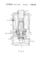
- FIG. 1 is a cross-sectional illustration of a three-way solenoid valve embodying an example of the present invention in an energized state
- FIG. 2 is a cross-sectional illustration of the valve shown in FIG. 1 in a nonenergized state.
- FIG. 1 there is shown a cross-sectional illustration of a three-way solenoid valve embodying an example of the present invention and having a valve base or body 2 with a first fluid port 4 connected to a fluid channel 6 in the valve body 2.
- a second fluid port 8 in the valve body 2 is connected to a fluid channel 10 which terminates in a fluid orifice 12 communicating with the fluid channel 6 in the valve body 2.
- a fluid sealing ring 14 is peripherally captured by an annular collar 16 attached to a first end 17 of a movable armature 18.
- the sealing ring 14 is exposed to the orifice 12 and is arranged to peripherally seal the orifice 12 in a deenergized state of the valve.
- the sealing ring 14 is coaxially aligned with a first end 15 of a longitudinal bore 20 extending through the armature 18.
- a second end 22 of the armature 18 is provided with an outwardly projecting fluid sealing member, e.g., O-ring 24, coaxially surrounding the bore 20.
- the armature 18 is located within a cylindrical sleeve 26 having one end supported on the valve body 2.
- a fixed end stop 27 is retained within the other end of the sleeve 26 adjacent to the second end 22 of the armature 18 to provide a fluid sealing surface for the fluid sealing member 24.
- a coaxial spring 28 is arranged to have one end supported on a shoulder 29 of the collar 16 to urge the armature 18 and the ring 14 against the orifice 12.
- the other end of the spring 28 is arranged to bear against an outer edge 30 of a rolling diaphragm seal 31 coaxially surrounding the armature 18 and having an inner edge 32 attached to an outer surface of the armature 18 to provide a fluid tight seal therewith.
- the outer edge 30 of the diaphragm 31 is further captured between the valve body 2 and a retaining ring 33 having peripheral fluid channels 34 therein.
- a third fluid port 35 is located in the valve body 2 on the other side of the diaphragm seal 31 from the first port 4 whereby the third port 35 is isolated from the first port 4 by the diaphragm seal 31.
- the third port 35 is connected to an annular recess 37 communicating with the fluid channels 34 in the ring 33.
- a solenoid coil assembly 38 in the form of an annulus surrounding a portion of the sleeve 26 adjacent to the armature 18 is supported on the valve body 2.
- the solenoid coil assembly 38 is shown in simplified form in FIGS. 1 and 2 and may include an electromagnetic winding and a magnetic field structure.
- the solenoid coil 38 is provided with an electrical connection 40 through a grommet 42 in an outer cover 44 surrounding the solenoid coil asssembly 38 and mounted on the valve body 2.
- a retaining nut 46 on a threaded outer end of the end stop 27 extending past the cover 44 is used to retain the cover 44 on the valve body 2.
- the valve illustrated in FIG. 1 is shown in an energized state, i.e., electrical current is applied to the solenoid coil 38 from a power supply (not shown) to move the armature 18, wherein the armature 18 is in a first position and the sealing ring 14 is spaced from the orifice 12.
- the sealing member 24 is in contact with the end plug 27 to effect a fluid-tight seal therewith whereby a fluid path between the bore 20 in the armature 18 and channels 36 on the surface of the armature 18 is interrupted.
- the first fluid port 4 is connected to the second fluid port 8 through the orifice 12 and the fluid channels 6 and 10 to provide a fluid flow channel therebetween.
- FIG. 2 there is shown a nonenergized state of the valve, i.e., the solenoid coil 38 is deenergized, wherein the armature 18 is in a second position, and the sealing ring 14 is urged against the periphery of the orifice 12 by the spring 28.
- the first inlet port 4 is isolated from the second outlet port 8 and the third outlet port 32 while a fluid channel is provided from the second outlet port 8 to the outlet port 32 through the coaxial bore 20 in the armature 18 since the sealing member 24 is now spaced from the end plug 27.
- the fluid flow is effected through the bore 18 and the channels 36 on the armature 18 to provide a fluid channel between the second fluid port 8 and the third fluid port 32.
- the valve of the present invention When the valve of the present invention is deenergized, the first port 4 and the area surrounding the orifice 12 and the sealing ring 14 are exposed to the same pressure. Concurrently, the outlet port 32 is open to the second port 8 whereby the top and bottom of the armature 18 are exposed to the same low pressure whereby there is essentially no net pressure force acting on the armature 18 to resist its movement by the magnetic field produced by the energization of the solenoid 38. Additionally, any net pressure force due to a difference between the diameter of the rolling diaphragm 31 and the diameter of the sealing ring 14 can be eliminated by a suitable design thereof. When the valve is energized, the seal member 24 interrupts the flow path to the third port 32.
- the first port 4 is now opened directly to the outlet port 8 through the orifice 12 which allows a pressure balance as a result of the pressure acting on the top of the armature 18, inside the seal ring 14 and the bottom of the armature 18.
- the fluid flow along the outside of the armature 18 through the channels 36 serves to provide an initial measure of static lubrication to the armature 18 whereby to facilitate the initial movement of the armature in response to a magnetic field from the solenoid 38.
- the fluid flow through the channels 36 is interrupted upon the separation of the seal ring 14 from the orifice 12 to minimize any dashpot effect on the armature 18.
- the advantages of the design of the present invention are to provide a pressure balanced armature which is exposed to a lubricating fluid flow to greatly reduce the magnetic force required to actuate the armature in a simple design which is economical to manufacture and provides a configuration wherein all of the ports are in the valve body.
Abstract
Description
Claims (16)
Priority Applications (4)
| Application Number | Priority Date | Filing Date | Title |
|---|---|---|---|
| US06/718,767 US4582294A (en) | 1985-04-01 | 1985-04-01 | Three-way solenoid valve |
| EP19860104173 EP0196621A3 (en) | 1985-04-01 | 1986-03-26 | Solenoid valve |
| CA000505271A CA1241251A (en) | 1985-04-01 | 1986-03-27 | Three-way solenoid valve |
| JP61072664A JPS61233280A (en) | 1985-04-01 | 1986-04-01 | Solenoid valve |
Applications Claiming Priority (1)
| Application Number | Priority Date | Filing Date | Title |
|---|---|---|---|
| US06/718,767 US4582294A (en) | 1985-04-01 | 1985-04-01 | Three-way solenoid valve |
Publications (1)
| Publication Number | Publication Date |
|---|---|
| US4582294A true US4582294A (en) | 1986-04-15 |
Family
ID=24887447
Family Applications (1)
| Application Number | Title | Priority Date | Filing Date |
|---|---|---|---|
| US06/718,767 Expired - Lifetime US4582294A (en) | 1985-04-01 | 1985-04-01 | Three-way solenoid valve |
Country Status (4)
| Country | Link |
|---|---|
| US (1) | US4582294A (en) |
| EP (1) | EP0196621A3 (en) |
| JP (1) | JPS61233280A (en) |
| CA (1) | CA1241251A (en) |
Cited By (48)
| Publication number | Priority date | Publication date | Assignee | Title |
|---|---|---|---|---|
| US4858956A (en) * | 1988-09-22 | 1989-08-22 | Siemens-Bendix Automotive Electronics L.P. | High pressure, fast response, pressure balanced, solenoid control valve |
| WO1989010510A2 (en) * | 1988-04-27 | 1989-11-02 | Gerhard Mesenich | Pulsed hydraulic valve |
| US4889148A (en) * | 1986-10-29 | 1989-12-26 | The Coca-Cola Company | Flow control valve for a dispensing system |
| US4901974A (en) * | 1989-05-11 | 1990-02-20 | Siemens-Bendix Automotive Electronics Limited | Canister purge solenoid valve |
| US5046530A (en) * | 1989-01-28 | 1991-09-10 | H. Kuhnke Gmbh Kg | Force-balanced lifting valve |
| US5100102A (en) * | 1990-10-15 | 1992-03-31 | Ford Motor Company | Compact electronic fuel injector |
| US5116020A (en) * | 1991-02-13 | 1992-05-26 | Industrial Technology Research Institute | Diaphragmatic electromagnetic valve with leakage preventing convex ring |
| US5188337A (en) * | 1990-12-13 | 1993-02-23 | Carl Freudenberg | Control valve with pressure equalization |
| US5396926A (en) * | 1993-03-19 | 1995-03-14 | Cummins Engine Company, Inc. | Force balanced three-way solenoid valve |
| US5478045A (en) * | 1991-10-11 | 1995-12-26 | Caterpillar Inc. | Damped actuator and valve assembly |
| US5497806A (en) * | 1993-03-31 | 1996-03-12 | Cummins Engine Company, Inc. | Compact pin-within-a-sleeve three-way valve |
| US5518030A (en) * | 1994-12-12 | 1996-05-21 | Cummins Engine Company, Inc. | Three-way flow valve with variable drain orifice area |
| US5579741A (en) * | 1995-11-30 | 1996-12-03 | Siemens Electric Limited | Vapor purge valve having tapered bead armature seal |
| US5651501A (en) * | 1993-12-23 | 1997-07-29 | Caterpillar Inc. | Fluid damping of a valve assembly |
| US6045120A (en) * | 1998-01-13 | 2000-04-04 | Cummins Engine Company, Inc. | Flow balanced spill control valve |
| FR2784439A1 (en) * | 1998-10-13 | 2000-04-14 | Peugeot | Electrically operated hydraulic valve for mounting on multiple valve block, comprises operating coil, screwed into block, whose plunger acts on three-way ball valve accommodated in block |
| US6158466A (en) * | 1999-01-14 | 2000-12-12 | Parker-Hannifin Corporation | Four-way flow reversing valve for reversible refrigeration cycles |
| US6199533B1 (en) | 1999-02-01 | 2001-03-13 | Cummins Engine Company, Inc. | Pilot valve controlled three-way fuel injection control valve assembly |
| US6217001B1 (en) * | 1999-06-29 | 2001-04-17 | Delphi Technologies, Inc. | Pressure balanced gas valve |
| US6405755B1 (en) * | 1998-12-01 | 2002-06-18 | Rapa Rausch & Pausch Elektrotechnische Spezialfabrik Gmbh | Directly controlled magnetic valve |
| US6435143B2 (en) * | 2000-03-01 | 2002-08-20 | Thomas J. Hollis | Three-way solenoid valve for actuating flow control valves in a temperature control system |
| US6676108B1 (en) * | 1997-08-04 | 2004-01-13 | Erwin Weh | Control valve |
| US20040041114A1 (en) * | 2002-03-19 | 2004-03-04 | Ichiro Hirata | Solenoid valve |
| US20040232372A1 (en) * | 2003-05-21 | 2004-11-25 | Mccombs Norman R. | Solenoid valve |
| US20040262562A1 (en) * | 2003-06-26 | 2004-12-30 | Maula Jarmo Ilmari | Diaphragm valve with reliability enhancements for atomic layer deposition |
| US20040261850A1 (en) * | 2003-06-26 | 2004-12-30 | Maula Jarmo Ilmari | Diaphragm valve for high-temperature precursor supply in atomic layer deposition |
| US20050011555A1 (en) * | 2003-06-26 | 2005-01-20 | Maula Jarmo Ilmari | High-speed diaphragm valve for atomic layer deposition |
| US20050151011A1 (en) * | 2002-01-31 | 2005-07-14 | Marotta Controls, Inc. | Method and system for controlling the operation of a valve |
| US20050269538A1 (en) * | 2004-06-07 | 2005-12-08 | Borgwarner Inc. | Low leak poppet solenoid |
| WO2005119339A1 (en) * | 2004-05-20 | 2005-12-15 | Laser Lock Technologies, Inc. | Illumination sources and subjects having distinctly matched and mismatched narrow spectral bands |
| US20060005823A1 (en) * | 2004-06-10 | 2006-01-12 | National Paintball Supply, Inc. | Valve assembly for a compressed gas gun |
| US20060064980A1 (en) * | 2004-09-28 | 2006-03-30 | Kirk Ivens | Turbo control valve utilizing a permanent magnet |
| US20060131531A1 (en) * | 2004-11-30 | 2006-06-22 | Keihin Corporation | Solenoid-operated valve for use with fuel cells |
| US20080042095A1 (en) * | 2006-08-17 | 2008-02-21 | Jabcon Jr Leonard J | Valve assembly |
| CN100386548C (en) * | 2003-05-21 | 2008-05-07 | 松下电器产业株式会社 | Break valve and its assembly method |
| US20080210312A1 (en) * | 2005-01-31 | 2008-09-04 | Swagelok Company | Flow control device |
| US20090242814A1 (en) * | 2008-03-26 | 2009-10-01 | Parker-Hannifin Corporation | Valve |
| WO2010088108A2 (en) * | 2009-01-27 | 2010-08-05 | Borgwarner Inc. | Open end variable bleed solenoid (vbs) valve with inherent viscous dampening |
| US20110062364A1 (en) * | 2009-09-16 | 2011-03-17 | Scherer Georg J | Solenoid |
| US20110284782A1 (en) * | 2010-05-24 | 2011-11-24 | Robert John Boychuk | Pressurized o-ring pole piece seal for a manifold |
| US20130056660A1 (en) * | 2010-05-10 | 2013-03-07 | Borgwarner Inc. | Electronic coolant valve with integral actuator mechanism |
| US9159016B2 (en) | 2013-03-14 | 2015-10-13 | LaserLock Technologies Inc. | System and method for providing tangible medium with electromagnetic security marker |
| US9183688B2 (en) | 2013-02-19 | 2015-11-10 | LaserLock Technologies Inc. | Characteristic verification system |
| US9377126B2 (en) * | 2013-07-22 | 2016-06-28 | Schaeffler Technologies AG & Co. KG | Control valve with integral pressure switch |
| US9482358B2 (en) | 2013-10-23 | 2016-11-01 | Johnson Electric S.A. | Solenoid valve |
| US20190170261A1 (en) * | 2015-07-09 | 2019-06-06 | Vistadeltek, Llc | Control plate in a valve |
| US10993546B2 (en) * | 2016-10-28 | 2021-05-04 | Sleep Number Corporation | Noise reducing plunger |
| US11832728B2 (en) | 2021-08-24 | 2023-12-05 | Sleep Number Corporation | Controlling vibration transmission within inflation assemblies |
Families Citing this family (9)
| Publication number | Priority date | Publication date | Assignee | Title |
|---|---|---|---|---|
| JPS63168377U (en) * | 1987-04-22 | 1988-11-02 | ||
| US4921208A (en) * | 1989-09-08 | 1990-05-01 | Automatic Switch Company | Proportional flow valve |
| JPH0446277A (en) * | 1990-06-13 | 1992-02-17 | Konan Denki Kk | Universal three-port two-position electromagnetic changeover valve |
| SE467707B (en) * | 1991-01-16 | 1992-08-31 | Mecman Ab | PROTECTOR CONTAINS A DRAINAGE DRAIN WITH AN ELECTRIC CONTROLLED PNEUMATIC VALVE |
| JP3274468B2 (en) * | 1992-11-10 | 2002-04-15 | キャタピラー インコーポレイテッド | Solenoid valve assembly |
| GB2311359A (en) * | 1996-03-23 | 1997-09-24 | Lucas Ind Plc | Valve |
| JP2006349142A (en) * | 2005-06-20 | 2006-12-28 | Borgwarner Inc | Low leakage poppet solenoid valve |
| KR102043966B1 (en) * | 2018-03-29 | 2019-11-12 | 주식회사 인팩 | Solenoid valve assembly for switching drive mode in suspension system |
| EP3839308A1 (en) * | 2019-12-20 | 2021-06-23 | Siemens Schweiz AG | Expansion valve |
Citations (6)
| Publication number | Priority date | Publication date | Assignee | Title |
|---|---|---|---|---|
| US2601989A (en) * | 1947-10-08 | 1952-07-01 | Powers Regulator Co | Balanced three-way valve |
| US2886063A (en) * | 1957-08-12 | 1959-05-12 | Gen Controls Co | Valve structure |
| US3007672A (en) * | 1960-12-21 | 1961-11-07 | Union Tank Car Co | Electromagnetically operated valve |
| DE3111716A1 (en) * | 1981-03-25 | 1982-10-07 | Joachim Dipl.-Ing. 7551 Bischweier Scholz | Electromagnetically operable double seat valve |
| US4376447A (en) * | 1979-08-20 | 1983-03-15 | Umc Industries, Inc. | Hot water valve |
| JPS58178077A (en) * | 1982-04-08 | 1983-10-18 | Hitachi Ltd | Pressure control valve |
Family Cites Families (2)
| Publication number | Priority date | Publication date | Assignee | Title |
|---|---|---|---|---|
| US3071147A (en) * | 1960-01-11 | 1963-01-01 | Bendix Westinghouse Automotive | Fluid pressure feed or reducing valve |
| DE2826973A1 (en) * | 1978-06-20 | 1980-01-17 | Knorr Bremse Gmbh | MAGNETIC VALVE |
-
1985
- 1985-04-01 US US06/718,767 patent/US4582294A/en not_active Expired - Lifetime
-
1986
- 1986-03-26 EP EP19860104173 patent/EP0196621A3/en not_active Withdrawn
- 1986-03-27 CA CA000505271A patent/CA1241251A/en not_active Expired
- 1986-04-01 JP JP61072664A patent/JPS61233280A/en active Pending
Patent Citations (6)
| Publication number | Priority date | Publication date | Assignee | Title |
|---|---|---|---|---|
| US2601989A (en) * | 1947-10-08 | 1952-07-01 | Powers Regulator Co | Balanced three-way valve |
| US2886063A (en) * | 1957-08-12 | 1959-05-12 | Gen Controls Co | Valve structure |
| US3007672A (en) * | 1960-12-21 | 1961-11-07 | Union Tank Car Co | Electromagnetically operated valve |
| US4376447A (en) * | 1979-08-20 | 1983-03-15 | Umc Industries, Inc. | Hot water valve |
| DE3111716A1 (en) * | 1981-03-25 | 1982-10-07 | Joachim Dipl.-Ing. 7551 Bischweier Scholz | Electromagnetically operable double seat valve |
| JPS58178077A (en) * | 1982-04-08 | 1983-10-18 | Hitachi Ltd | Pressure control valve |
Cited By (74)
| Publication number | Priority date | Publication date | Assignee | Title |
|---|---|---|---|---|
| US4889148A (en) * | 1986-10-29 | 1989-12-26 | The Coca-Cola Company | Flow control valve for a dispensing system |
| WO1989010510A2 (en) * | 1988-04-27 | 1989-11-02 | Gerhard Mesenich | Pulsed hydraulic valve |
| WO1989010510A3 (en) * | 1988-04-27 | 1989-11-30 | Gerhard Mesenich | Pulsed hydraulic valve |
| US4979542A (en) * | 1988-04-27 | 1990-12-25 | Siemens Automotive L.P. | Pulse modulated hydraulic valve |
| JPH03500080A (en) * | 1988-04-27 | 1991-01-10 | メゼニヒ,ゲルハルト | pulse hydraulic valve |
| US4858956A (en) * | 1988-09-22 | 1989-08-22 | Siemens-Bendix Automotive Electronics L.P. | High pressure, fast response, pressure balanced, solenoid control valve |
| US5046530A (en) * | 1989-01-28 | 1991-09-10 | H. Kuhnke Gmbh Kg | Force-balanced lifting valve |
| US4901974A (en) * | 1989-05-11 | 1990-02-20 | Siemens-Bendix Automotive Electronics Limited | Canister purge solenoid valve |
| US5100102A (en) * | 1990-10-15 | 1992-03-31 | Ford Motor Company | Compact electronic fuel injector |
| US5188337A (en) * | 1990-12-13 | 1993-02-23 | Carl Freudenberg | Control valve with pressure equalization |
| US5116020A (en) * | 1991-02-13 | 1992-05-26 | Industrial Technology Research Institute | Diaphragmatic electromagnetic valve with leakage preventing convex ring |
| US5478045A (en) * | 1991-10-11 | 1995-12-26 | Caterpillar Inc. | Damped actuator and valve assembly |
| US5396926A (en) * | 1993-03-19 | 1995-03-14 | Cummins Engine Company, Inc. | Force balanced three-way solenoid valve |
| US5497806A (en) * | 1993-03-31 | 1996-03-12 | Cummins Engine Company, Inc. | Compact pin-within-a-sleeve three-way valve |
| US5651501A (en) * | 1993-12-23 | 1997-07-29 | Caterpillar Inc. | Fluid damping of a valve assembly |
| US5518030A (en) * | 1994-12-12 | 1996-05-21 | Cummins Engine Company, Inc. | Three-way flow valve with variable drain orifice area |
| US5579741A (en) * | 1995-11-30 | 1996-12-03 | Siemens Electric Limited | Vapor purge valve having tapered bead armature seal |
| US6676108B1 (en) * | 1997-08-04 | 2004-01-13 | Erwin Weh | Control valve |
| US6045120A (en) * | 1998-01-13 | 2000-04-04 | Cummins Engine Company, Inc. | Flow balanced spill control valve |
| FR2784439A1 (en) * | 1998-10-13 | 2000-04-14 | Peugeot | Electrically operated hydraulic valve for mounting on multiple valve block, comprises operating coil, screwed into block, whose plunger acts on three-way ball valve accommodated in block |
| US6405755B1 (en) * | 1998-12-01 | 2002-06-18 | Rapa Rausch & Pausch Elektrotechnische Spezialfabrik Gmbh | Directly controlled magnetic valve |
| US6158466A (en) * | 1999-01-14 | 2000-12-12 | Parker-Hannifin Corporation | Four-way flow reversing valve for reversible refrigeration cycles |
| US6199533B1 (en) | 1999-02-01 | 2001-03-13 | Cummins Engine Company, Inc. | Pilot valve controlled three-way fuel injection control valve assembly |
| US6217001B1 (en) * | 1999-06-29 | 2001-04-17 | Delphi Technologies, Inc. | Pressure balanced gas valve |
| US6435143B2 (en) * | 2000-03-01 | 2002-08-20 | Thomas J. Hollis | Three-way solenoid valve for actuating flow control valves in a temperature control system |
| US20050151011A1 (en) * | 2002-01-31 | 2005-07-14 | Marotta Controls, Inc. | Method and system for controlling the operation of a valve |
| US20040041114A1 (en) * | 2002-03-19 | 2004-03-04 | Ichiro Hirata | Solenoid valve |
| US7017885B2 (en) * | 2002-03-19 | 2006-03-28 | Nok Corporation | Solenoid valve |
| US6935612B2 (en) * | 2003-05-21 | 2005-08-30 | Airsep Corporation | Solenoid valve |
| CN100386548C (en) * | 2003-05-21 | 2008-05-07 | 松下电器产业株式会社 | Break valve and its assembly method |
| US20040232372A1 (en) * | 2003-05-21 | 2004-11-25 | Mccombs Norman R. | Solenoid valve |
| US20050011555A1 (en) * | 2003-06-26 | 2005-01-20 | Maula Jarmo Ilmari | High-speed diaphragm valve for atomic layer deposition |
| US6907897B2 (en) | 2003-06-26 | 2005-06-21 | Planar Systems, Inc. | Diaphragm valve for high-temperature precursor supply in atomic layer deposition |
| US20040261850A1 (en) * | 2003-06-26 | 2004-12-30 | Maula Jarmo Ilmari | Diaphragm valve for high-temperature precursor supply in atomic layer deposition |
| US20040262562A1 (en) * | 2003-06-26 | 2004-12-30 | Maula Jarmo Ilmari | Diaphragm valve with reliability enhancements for atomic layer deposition |
| US6941963B2 (en) | 2003-06-26 | 2005-09-13 | Planar Systems, Inc. | High-speed diaphragm valve for atomic layer deposition |
| US7021330B2 (en) | 2003-06-26 | 2006-04-04 | Planar Systems, Inc. | Diaphragm valve with reliability enhancements for atomic layer deposition |
| US7191793B2 (en) | 2003-06-26 | 2007-03-20 | Planar Systems, Inc. | Diaphragm valve for atomic layer deposition |
| WO2005119339A1 (en) * | 2004-05-20 | 2005-12-15 | Laser Lock Technologies, Inc. | Illumination sources and subjects having distinctly matched and mismatched narrow spectral bands |
| US8551683B2 (en) | 2004-05-20 | 2013-10-08 | Laserlock Technologies, Inc. | Illumination sources and subjects having distinctly matched and mismatched narrow spectral bands |
| US8841063B2 (en) | 2004-05-20 | 2014-09-23 | Laserlock Technologies, Inc. | Illumination sources and subjects having distinctly matched and mismatched narrow spectral bands |
| US20090050829A1 (en) * | 2004-06-07 | 2009-02-26 | Brogwarner Inc. | Low leak poppet solenoid |
| US20050269538A1 (en) * | 2004-06-07 | 2005-12-08 | Borgwarner Inc. | Low leak poppet solenoid |
| US7458395B2 (en) * | 2004-06-07 | 2008-12-02 | Borgwarner Inc. | Low leak poppet solenoid |
| US7913679B2 (en) * | 2004-06-10 | 2011-03-29 | Kee Action Sports I Llc | Valve assembly for a compressed gas gun |
| US20060005823A1 (en) * | 2004-06-10 | 2006-01-12 | National Paintball Supply, Inc. | Valve assembly for a compressed gas gun |
| US8302390B2 (en) * | 2004-09-28 | 2012-11-06 | Continental Automotive Systems Us, Inc. | Turbo control valve utilizing a permanent magnet |
| US20060064980A1 (en) * | 2004-09-28 | 2006-03-30 | Kirk Ivens | Turbo control valve utilizing a permanent magnet |
| US7401762B2 (en) * | 2004-11-30 | 2008-07-22 | Keihin Corporation | Solenoid-operated valve for use with fuel cells |
| US20060131531A1 (en) * | 2004-11-30 | 2006-06-22 | Keihin Corporation | Solenoid-operated valve for use with fuel cells |
| US20080210312A1 (en) * | 2005-01-31 | 2008-09-04 | Swagelok Company | Flow control device |
| US7849876B2 (en) * | 2006-08-17 | 2010-12-14 | Parker-Hannifin Corporation | Valve assembly with sealing force |
| US20080042095A1 (en) * | 2006-08-17 | 2008-02-21 | Jabcon Jr Leonard J | Valve assembly |
| US20090242814A1 (en) * | 2008-03-26 | 2009-10-01 | Parker-Hannifin Corporation | Valve |
| US8430377B2 (en) * | 2008-03-26 | 2013-04-30 | Parker-Hannifin Corporation | Valve |
| WO2010088108A3 (en) * | 2009-01-27 | 2010-11-04 | Borgwarner Inc. | Open end variable bleed solenoid (vbs) valve with inherent viscous dampening |
| CN102292581A (en) * | 2009-01-27 | 2011-12-21 | 博格华纳公司 | Open end variable bleed solenoid (vbs) valve with inherent viscous dampening |
| US20110284783A1 (en) * | 2009-01-27 | 2011-11-24 | Borgwarner Inc. | Open end variable bleed solenoid (vbs) valve with inherent viscous dampening |
| WO2010088108A2 (en) * | 2009-01-27 | 2010-08-05 | Borgwarner Inc. | Open end variable bleed solenoid (vbs) valve with inherent viscous dampening |
| US8641011B2 (en) * | 2009-09-16 | 2014-02-04 | SVM Schultz Verwaltungs—GmbH & Co. KG | Solenoid with armature having frontal recess |
| US20110062364A1 (en) * | 2009-09-16 | 2011-03-17 | Scherer Georg J | Solenoid |
| US9068666B2 (en) * | 2010-05-10 | 2015-06-30 | Borgwarner Inc. | Electronic coolant valve with integral actuator mechanism |
| US20130056660A1 (en) * | 2010-05-10 | 2013-03-07 | Borgwarner Inc. | Electronic coolant valve with integral actuator mechanism |
| US8733732B2 (en) * | 2010-05-24 | 2014-05-27 | Eaton Corporation | Pressurized o-ring pole piece seal for a manifold |
| US20110284782A1 (en) * | 2010-05-24 | 2011-11-24 | Robert John Boychuk | Pressurized o-ring pole piece seal for a manifold |
| US9183688B2 (en) | 2013-02-19 | 2015-11-10 | LaserLock Technologies Inc. | Characteristic verification system |
| US9159016B2 (en) | 2013-03-14 | 2015-10-13 | LaserLock Technologies Inc. | System and method for providing tangible medium with electromagnetic security marker |
| US9377126B2 (en) * | 2013-07-22 | 2016-06-28 | Schaeffler Technologies AG & Co. KG | Control valve with integral pressure switch |
| US9482358B2 (en) | 2013-10-23 | 2016-11-01 | Johnson Electric S.A. | Solenoid valve |
| US20190170261A1 (en) * | 2015-07-09 | 2019-06-06 | Vistadeltek, Llc | Control plate in a valve |
| US10527177B2 (en) * | 2015-07-09 | 2020-01-07 | Vistadeltek, Llc | Control plate in a valve |
| US10993546B2 (en) * | 2016-10-28 | 2021-05-04 | Sleep Number Corporation | Noise reducing plunger |
| US11950702B2 (en) | 2016-10-28 | 2024-04-09 | Sleep Number Corporation | Noise reducing plunger |
| US11832728B2 (en) | 2021-08-24 | 2023-12-05 | Sleep Number Corporation | Controlling vibration transmission within inflation assemblies |
Also Published As
| Publication number | Publication date |
|---|---|
| JPS61233280A (en) | 1986-10-17 |
| CA1241251A (en) | 1988-08-30 |
| EP0196621A3 (en) | 1987-01-21 |
| EP0196621A2 (en) | 1986-10-08 |
Similar Documents
| Publication | Publication Date | Title |
|---|---|---|
| US4582294A (en) | Three-way solenoid valve | |
| US4546955A (en) | Two-stage solenoid valve | |
| US4624282A (en) | Two-stage solenoid valve | |
| US2930404A (en) | Three-way poppet-valve construction for plug-type valve | |
| US4655249A (en) | Electromagnetic valve | |
| US3368789A (en) | Electromagnetic valve | |
| US3405906A (en) | Solenoid pilot operated valve | |
| US4848721A (en) | Hydraulic valve with integrated solenoid | |
| US3521854A (en) | Electromagnetically actuated valve with a plunger-type armature arrangement | |
| US4513780A (en) | Solenoid valve | |
| US3108777A (en) | Oil-filled solenoid gas valve | |
| US4251051A (en) | Solenoid structure having a relatively unrestrained generally flat armature member | |
| US4304264A (en) | Solenoid actuated valve | |
| US3942759A (en) | Magnetically-actuated membrane valve | |
| US5064166A (en) | Solenoid valve with high flow capacity and low energy consumption | |
| US3521851A (en) | Floating valve seal | |
| US6290203B1 (en) | Pilot operated valve assembly | |
| EP0795706B1 (en) | Universal on/off solenoid valve assembly | |
| US3410308A (en) | Moving coil electrohydraulic servovalve | |
| CA1216494A (en) | Electrically actuated valve assembly | |
| US7246787B2 (en) | Solenoid valve assembly | |
| WO2006065786A2 (en) | Magnetically-actuated manually-operated isolation valve | |
| US4832313A (en) | Solenoid valve | |
| US4694270A (en) | Electromagnetic proportional actuator | |
| US2679856A (en) | Pilot operated valve for controlling the flow of fluids |
Legal Events
| Date | Code | Title | Description |
|---|---|---|---|
| AS | Assignment |
Owner name: HONEYWELL INC., MINNEAPOLIS,HENNEPIN MINNESOTA A C Free format text: ASSIGNMENT OF ASSIGNORS INTEREST.;ASSIGNOR:FARGO, RICHARD N.;REEL/FRAME:004391/0324 Effective date: 19850319 |
|
| FEPP | Fee payment procedure |
Free format text: PAYER NUMBER DE-ASSIGNED (ORIGINAL EVENT CODE: RMPN); ENTITY STATUS OF PATENT OWNER: LARGE ENTITY Free format text: PAYOR NUMBER ASSIGNED (ORIGINAL EVENT CODE: ASPN); ENTITY STATUS OF PATENT OWNER: LARGE ENTITY |
|
| STCF | Information on status: patent grant |
Free format text: PATENTED CASE |
|
| FPAY | Fee payment |
Year of fee payment: 4 |
|
| FPAY | Fee payment |
Year of fee payment: 8 |
|
| FPAY | Fee payment |
Year of fee payment: 12 |
|
| AS | Assignment |
Owner name: PARKER INTANGIBLES INC., DELAWARE Free format text: REASSIGNMENT;ASSIGNOR:HONEYWELL INC.;REEL/FRAME:008855/0881 Effective date: 19971114 |
|
| AS | Assignment |
Owner name: PARKER HANNIFAN CUSTOMER SUPPORT INC., CALIFORNIA Free format text: MERGER;ASSIGNOR:PARKER INTANGIBLES INC.;REEL/FRAME:010308/0269 Effective date: 19981231 |