US4580696A - Retainer and dispenser for food containers in fast food establishment - Google Patents
Retainer and dispenser for food containers in fast food establishment Download PDFInfo
- Publication number
- US4580696A US4580696A US06/639,435 US63943584A US4580696A US 4580696 A US4580696 A US 4580696A US 63943584 A US63943584 A US 63943584A US 4580696 A US4580696 A US 4580696A
- Authority
- US
- United States
- Prior art keywords
- housing
- stack
- cups
- dispenser
- cup
- Prior art date
- Legal status (The legal status is an assumption and is not a legal conclusion. Google has not performed a legal analysis and makes no representation as to the accuracy of the status listed.)
- Expired - Fee Related
Links
- 235000013410 fast food Nutrition 0.000 title claims abstract description 5
- 235000013305 food Nutrition 0.000 title description 2
- 239000011087 paperboard Substances 0.000 claims 1
- 235000002595 Solanum tuberosum Nutrition 0.000 abstract description 6
- 244000061456 Solanum tuberosum Species 0.000 abstract description 6
- 235000012015 potatoes Nutrition 0.000 abstract description 6
- 238000000034 method Methods 0.000 description 2
- 230000000717 retained effect Effects 0.000 description 2
- 238000010276 construction Methods 0.000 description 1
- 235000012020 french fries Nutrition 0.000 description 1
- 238000004519 manufacturing process Methods 0.000 description 1
Images

Classifications
-
- A—HUMAN NECESSITIES
- A47—FURNITURE; DOMESTIC ARTICLES OR APPLIANCES; COFFEE MILLS; SPICE MILLS; SUCTION CLEANERS IN GENERAL
- A47F—SPECIAL FURNITURE, FITTINGS, OR ACCESSORIES FOR SHOPS, STOREHOUSES, BARS, RESTAURANTS OR THE LIKE; PAYING COUNTERS
- A47F1/00—Racks for dispensing merchandise; Containers for dispensing merchandise
- A47F1/04—Racks or containers with arrangements for dispensing articles, e.g. by means of gravity or springs
- A47F1/08—Racks or containers with arrangements for dispensing articles, e.g. by means of gravity or springs dispensing from bottom
- A47F1/085—Racks or containers with arrangements for dispensing articles, e.g. by means of gravity or springs dispensing from bottom for nested articles, e.g. cups, cones
Definitions
- french fried potatoes and the like are sold.
- An order of french fried potatoes is usually served to a customer in a paper-like container or cup, sometimes referred to as a scoop.
- a supply of the containers or cups or scoops is customarily maintained in a stacked nested condition.
- the attendant or waitress removes one of the cups or containers from the stack.
- the cup has an extending wall portion and is moved in a scooping acting during filling thereof from a supply of french fried potatoes.
- the attendant or waitress must employ both hands to remove a cup or container from the stack. In so doing, more than one cup may, inadvertently, be removed from the stack and may have to be replaced in the stack or discarded.
- difficulty is encountered in removing a cup or container from the unit. It is sometimes necessary to use two hands to remove a cup or container from a conventional holder or dispenser. It is sometimes difficult to remove a cup without also withdrawing another cup from the dispenser.
- This invention comprises a retainer and dispenser for cups or containers or scoops which are adapted to contain french fried potatoes or other foods, or the like.
- the holder and dispenser comprises a housing or frame member which is adapted to be attached to a wall or other support member.
- the housing or frame has an opening in the upper portion thereof to receive a stack of nested cups or containers.
- the stack of cups is retained in the retainer and dispenser with the cups in an inverted position.
- the holder and dispenser has one or more members forming a guide for movement of the cups downwardly from the opening in the upper portion thereof.
- the housing or frame has an opening in the lower portion thereof through which the cups move from the housing or frame.
- each cup has a portion which extends from the opening therein.
- At the lower portion of the housing or frame is one or more abutment members, engageable by the extending wall portion of the lowermost cup in the nested stack thereof.
- the extending wall portion of the lowermost cup is manually grasped and deflected from the abutment member.
- the cup which is next immediately above the lowermost cup falls downwardly.
- the extending wall thereof engages the abutment member and prevents the cup from moving from the opening in the lower portion of the frame or housing.
- the other cups in the nested stack thereof move downwardly as the lowermost cup is removed from the stack.
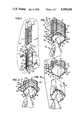
- FIG. 1 is an exploded perspective view showing the cup retainer and dispenser of this invention and illustrating movement of a nested stack of cups into the retainer and dispenser.
- FIG. 2 is a fragmentary perspective view, drawn on a larger scale than FIG. 1, showing a nested stack of cups within the retainer and dispenser and illustrating an initial step in removing a cup from the retainer and dispenser.
- FIG. 3 is a fragmentary perspective view, similar to FIG. 2, illustrating a succeeding step in removal of a cup from the retainer and dispenser.
- FIG. 4 is a fragmentary perspective view similar to FIGS. 2 and 3, illustrating a further step in removal of a cup from the retainer and dispenser and illustrating the position assumed by a succeeding cup as the preceding cup moves from the retainer and dispenser.
- FIG. 5 is a fragmentary elevational view taken substantially on line 5--5 of FIG. 2, drawn on a larger scale than the preceding figures. This figure shows the nested cups prior to the first step in removal of the lowermost cup from the stack thereof.
- FIG. 6 is a fragmentary elevational view similar to FIG. 5, but illustrating an initial step in removal of the lowermost cup from the stack thereof.
- FIG. 7 is a fragmentary elevational view similar to FIG. 5 and 6 and illustrating a succeeding step in removal of the lowermost cup from the nested stack thereof.
- FIG. 8 is a fragmentary elevational view similar to FIGS. 5-7, and illustrating a further step in removing a cup from the nested stack thereof.
- a retainer and dispenser of this invention comprises a housing 16.
- the housing 16 may be constructed of any suitable elements or materials.
- the housing 16 is shown as being elongate and adapted to be oriented substantially vertically.
- the housing 16 is shown as comprising a plurality of rigid wire members or rod members 20 which are attached together and arranged and shaped to provide an opening 24 at the upper portion thereof and an opening 30 at the lower portion thereof.
- the opening 24 at the upper portion of the housing 16 is larger than the opening 30 at the lower portion thereof.
- the wire members 20 include an upper substantially horizontal back portion 20a joined to horizontal opposed side portions 20b. Extending downwardly from the upper horizontal back portion 20a is a pair of vertical wire members 20d. Attached to the vertical wire members 20d and spaced below the horizontal back portion 20a and the side portions 20b is a horizontal intermediate wire member 20e which is shown as being substantially rectangular in shape.
- a lower horizontal wire member 20f which is shown as being substantially rectangular in shape.
- a horizontal back base portion 20g Attached to the horizontal base side portions 20h and spaced forwardly from the horizontal back base portion 20g and substantially parallel thereto is a horizontal connector wire member 20a.
- a pair of elongate wire members 20j Extending downwardly from the upper back portion 20a is a pair of elongate wire members 20j which slope forwardly from the back portion 20a and then extend vertically downwardly therefrom.
- the wire members 20j are spaced from the horizontal intermediate wire member 20e and are spaced from the lower horizontal wire member 20f.
- the wire members 20j are attached to the connector wire member 20e and extend downwardly therefrom.
- an abutment member 36 At the lower end of each of the wire members 20j is an abutment member 36, herein shown as being substantially spherical in shape.
- the wire members 20k Attached to the horizontal side portions 20b and extending angularly downwardly therefrom are side wire members 20k.
- the wire members 20k are attached to the horizontal intermediate wire member 20e and extend vertically downwardly therefrom and are attached to the lower horizontal wire member 20f.
- the wire members 20k extend from the lower horizontal wire member 20f to the horizontal base side portions 20h.
- the wire members 20e and 20f may not be rectangular in shape and may be open between the front wire members 20k.
- bracket elements 38 and 39 are employed to attach the housing 16 to a wall 44 or other support member, as the bracket elements encompass the vertical wire members 20d.
- a nested stack of cups or containers 40 is readily inserted into the housing 16 through the opening 24 in the upper portion of the housing 16.
- the nested stack of cups or containers 40 is inserted into the housing 16 with the opening in each cup 40 in a downward orientation.
- the cups 40 are inverted as they are positioned within the housing 16.
- the opening 24 in the upper portion of the housing 16 is sufficiently large to permit a stack of cups to be readily inserted into the housing 16.
- a space is provided between the side portions 20b so that a person's hand may be inserted between the side portions 20b to assist in guiding downward movement of the nested stack of cups 40 into the housing 16.
- the vertical wire members 20j and 20k assist in guiding downward movement of the cups 40 from the opening 24.
- each cup 40 has an extending back wall 46.
- the extending back wall 46 of the lowermost cup 40 engages the abutment members 36.
- the position of the nested stack of cups 40 is established within the housing 16, as illustrated in FIGS. 2 and 5.
- the extending back wall 46 of the lowermost cup 40 is grasped by a person's fingers, as illustrated in FIGS. 2 and 5. Due to the fact that there is no element between the base side portions 20h at the front part of the housing 16, and due to the fact that the lower ends of the wire members 20j are spaced forwardly from the back base portion 20g, a person's fingers can easily and readily reach the extending back wall portion 46 of the lowermost cup as the back wall portion 46 rests upon the abutment members 36. Then the extending back wall portion 46 of the lowermost cup 40 is bent or deflected slightly forwardly, as illustrated by an arrow 50 in FIGS. 2 and 6.
- the cups 40 in the nested stack thereof are easily and readily consecutively removed from the housing 16. Each cup 40 is readily removed, without the inadvertent simultaneous removal of more than one cup 40.
Abstract
Description
Claims (3)
Priority Applications (1)
| Application Number | Priority Date | Filing Date | Title |
|---|---|---|---|
| US06/639,435 US4580696A (en) | 1982-02-12 | 1984-08-10 | Retainer and dispenser for food containers in fast food establishment |
Applications Claiming Priority (2)
| Application Number | Priority Date | Filing Date | Title |
|---|---|---|---|
| US06/348,350 US4476996A (en) | 1982-02-12 | 1982-02-12 | Retainer and dispenser for food containers in fast food establishment |
| US06/639,435 US4580696A (en) | 1982-02-12 | 1984-08-10 | Retainer and dispenser for food containers in fast food establishment |
Related Parent Applications (1)
| Application Number | Title | Priority Date | Filing Date |
|---|---|---|---|
| US06/348,350 Continuation US4476996A (en) | 1982-02-12 | 1982-02-12 | Retainer and dispenser for food containers in fast food establishment |
Publications (1)
| Publication Number | Publication Date |
|---|---|
| US4580696A true US4580696A (en) | 1986-04-08 |
Family
ID=26995662
Family Applications (1)
| Application Number | Title | Priority Date | Filing Date |
|---|---|---|---|
| US06/639,435 Expired - Fee Related US4580696A (en) | 1982-02-12 | 1984-08-10 | Retainer and dispenser for food containers in fast food establishment |
Country Status (1)
| Country | Link |
|---|---|
| US (1) | US4580696A (en) |
Cited By (5)
| Publication number | Priority date | Publication date | Assignee | Title |
|---|---|---|---|---|
| US5074431A (en) * | 1990-05-29 | 1991-12-24 | Sendelbach Herman E | Paper plate pantry |
| US5501365A (en) * | 1994-03-25 | 1996-03-26 | Playtex Products, Inc. | Package and system for dispensing preformed nurser sacs |
| US6619486B1 (en) * | 2002-03-25 | 2003-09-16 | Carlos J. Veloso | Flipper/catcher integrated with guide pin for up-stacking of die-cut thermoformed parts |
| US20040020555A1 (en) * | 2002-04-22 | 2004-02-05 | Sus Gerald A. | Automated food processing system and method |
| US20140311998A1 (en) * | 2011-12-29 | 2014-10-23 | Daniel Brian Tan | Bag container dispenser rack |
Citations (9)
| Publication number | Priority date | Publication date | Assignee | Title |
|---|---|---|---|---|
| US1134651A (en) * | 1914-04-09 | 1915-04-06 | Walter C Seale | Holder for lard and butter trays and like receptacles. |
| US1664164A (en) * | 1926-02-18 | 1928-03-27 | Waldemar A Endter | Carton-vending device |
| US1698239A (en) * | 1926-12-17 | 1929-01-08 | Ideal Cup Corp | Dispensing device |
| US1726813A (en) * | 1928-03-16 | 1929-09-03 | Waldemar A Endter | Carton dispenser |
| US2818996A (en) * | 1956-04-09 | 1958-01-07 | Kalamazoo Vegets Le Parchment | Dispenser for stacked dishes |
| US3152697A (en) * | 1963-12-09 | 1964-10-13 | Berman Jacob | Modular dispensing display rack |
| US4094443A (en) * | 1976-06-25 | 1978-06-13 | Ad-Tec Products, Inc. | Paint strainer dispenser |
| US4266665A (en) * | 1979-11-13 | 1981-05-12 | Research, Development & Marketing, Inc. | Dispenser for cup-shaped filters |
| US4476996A (en) * | 1982-02-12 | 1984-10-16 | Moore Jr Franklin | Retainer and dispenser for food containers in fast food establishment |
-
1984
- 1984-08-10 US US06/639,435 patent/US4580696A/en not_active Expired - Fee Related
Patent Citations (9)
| Publication number | Priority date | Publication date | Assignee | Title |
|---|---|---|---|---|
| US1134651A (en) * | 1914-04-09 | 1915-04-06 | Walter C Seale | Holder for lard and butter trays and like receptacles. |
| US1664164A (en) * | 1926-02-18 | 1928-03-27 | Waldemar A Endter | Carton-vending device |
| US1698239A (en) * | 1926-12-17 | 1929-01-08 | Ideal Cup Corp | Dispensing device |
| US1726813A (en) * | 1928-03-16 | 1929-09-03 | Waldemar A Endter | Carton dispenser |
| US2818996A (en) * | 1956-04-09 | 1958-01-07 | Kalamazoo Vegets Le Parchment | Dispenser for stacked dishes |
| US3152697A (en) * | 1963-12-09 | 1964-10-13 | Berman Jacob | Modular dispensing display rack |
| US4094443A (en) * | 1976-06-25 | 1978-06-13 | Ad-Tec Products, Inc. | Paint strainer dispenser |
| US4266665A (en) * | 1979-11-13 | 1981-05-12 | Research, Development & Marketing, Inc. | Dispenser for cup-shaped filters |
| US4476996A (en) * | 1982-02-12 | 1984-10-16 | Moore Jr Franklin | Retainer and dispenser for food containers in fast food establishment |
Cited By (13)
| Publication number | Priority date | Publication date | Assignee | Title |
|---|---|---|---|---|
| US5074431A (en) * | 1990-05-29 | 1991-12-24 | Sendelbach Herman E | Paper plate pantry |
| US5501365A (en) * | 1994-03-25 | 1996-03-26 | Playtex Products, Inc. | Package and system for dispensing preformed nurser sacs |
| US6619486B1 (en) * | 2002-03-25 | 2003-09-16 | Carlos J. Veloso | Flipper/catcher integrated with guide pin for up-stacking of die-cut thermoformed parts |
| US20040020555A1 (en) * | 2002-04-22 | 2004-02-05 | Sus Gerald A. | Automated food processing system and method |
| US7303776B2 (en) * | 2002-04-22 | 2007-12-04 | Restaurant Technology, Inc. | Automated food processing system and method |
| US20080063767A1 (en) * | 2002-04-22 | 2008-03-13 | Sus Gerald A | Automated device for erecting individual French fry containers and method |
| US20080063769A1 (en) * | 2002-04-22 | 2008-03-13 | Sus Gerald A | Automated fry vat and method |
| US20080060715A1 (en) * | 2002-04-22 | 2008-03-13 | Sus Gerald A | Automated method of packaging food items |
| US20080173649A1 (en) * | 2002-04-22 | 2008-07-24 | Sus Gerald A | Vibratory tray conveyor and method |
| US7824721B2 (en) | 2002-04-22 | 2010-11-02 | Restaurant Technology, Inc. | Automated method of packaging food items |
| US8770433B2 (en) | 2002-04-22 | 2014-07-08 | Restaurant Technology, Inc. | Vibratory tray conveyor and method |
| US20140311998A1 (en) * | 2011-12-29 | 2014-10-23 | Daniel Brian Tan | Bag container dispenser rack |
| US9140036B2 (en) * | 2011-12-29 | 2015-09-22 | Daniel Brian Tan | Bag container dispenser rack |
Similar Documents
| Publication | Publication Date | Title |
|---|---|---|
| US5328258A (en) | Pizza box storage and dispensing assembly | |
| US4508027A (en) | Portion dividing frying basket | |
| US5131562A (en) | Dispenser for soft drink lids and the like | |
| US5570808A (en) | Dispensers for protective gloves | |
| US4105126A (en) | Storage and dispensing rack | |
| US3203554A (en) | Can carton rack | |
| US4877609A (en) | Combination food server and container lid support | |
| US4502623A (en) | Precise volume, disposable food container | |
| US4476996A (en) | Retainer and dispenser for food containers in fast food establishment | |
| US5147119A (en) | Sock storage and dispensing apparatus | |
| US2466636A (en) | Service tray | |
| US4960210A (en) | Gravity feed gondola base | |
| US3014616A (en) | Butter patties | |
| US4580696A (en) | Retainer and dispenser for food containers in fast food establishment | |
| US20160058205A1 (en) | Display rack | |
| US3255570A (en) | Means for filling containers | |
| US6193067B1 (en) | Self-fronting merchandise display box | |
| US4121726A (en) | Apparatus for dispensing paper articles | |
| US2927699A (en) | Merchandise display device | |
| US4506607A (en) | Shelf-type driverless vehicle | |
| US2226626A (en) | Cracker dispenser | |
| US4266665A (en) | Dispenser for cup-shaped filters | |
| US1977400A (en) | Display stand | |
| US2222887A (en) | Automatic dispensing shelf | |
| US2940642A (en) | Dispensing bin for vegetables, etc. |
Legal Events
| Date | Code | Title | Description |
|---|---|---|---|
| CC | Certificate of correction | ||
| AS | Assignment |
Owner name: PROGRESSIVE PAPER PRODUCTS, INC., 300 INDUSTRY DR. Free format text: ASSIGNMENT OF ASSIGNORS INTEREST.;ASSIGNORS:MOORE, FRANKLIN JR.;FULTZ, CLINTON;REEL/FRAME:004668/0434 Effective date: 19861231 Owner name: PROGRESSIVE PAPER PRODUCTS, INC., A CORP. OF OH.,O Free format text: ASSIGNMENT OF ASSIGNORS INTEREST;ASSIGNORS:MOORE, FRANKLIN JR.;FULTZ, CLINTON;REEL/FRAME:004668/0434 Effective date: 19861231 |
|
| FPAY | Fee payment |
Year of fee payment: 4 |
|
| FPAY | Fee payment |
Year of fee payment: 8 |
|
| AS | Assignment |
Owner name: TEMPLE-INLAND FOOD SERVICE CORPORATION, INDIANA Free format text: MERGER;ASSIGNOR:PROGRESSIVE PAPER PRODUCTS, INC.;REEL/FRAME:008709/0168 Effective date: 19911226 |
|
| AS | Assignment |
Owner name: DOPACO, INC., PENNSYLVANIA Free format text: ASSIGNMENT OF ASSIGNORS INTEREST;ASSIGNOR:TEMPLE-INLAND FOOD SERVICE CORPORATION;REEL/FRAME:008955/0251 Effective date: 19971027 |
|
| REMI | Maintenance fee reminder mailed | ||
| LAPS | Lapse for failure to pay maintenance fees | ||
| FP | Lapsed due to failure to pay maintenance fee |
Effective date: 19980408 |
|
| STCH | Information on status: patent discontinuation |
Free format text: PATENT EXPIRED DUE TO NONPAYMENT OF MAINTENANCE FEES UNDER 37 CFR 1.362 |