US4579258A - Operating handle for aerosol container - Google Patents
Operating handle for aerosol container Download PDFInfo
- Publication number
- US4579258A US4579258A US06/542,530 US54253083A US4579258A US 4579258 A US4579258 A US 4579258A US 54253083 A US54253083 A US 54253083A US 4579258 A US4579258 A US 4579258A
- Authority
- US
- United States
- Prior art keywords
- trigger
- shell
- aerosol container
- hand grip
- grip portion
- Prior art date
- Legal status (The legal status is an assumption and is not a legal conclusion. Google has not performed a legal analysis and makes no representation as to the accuracy of the status listed.)
- Expired - Fee Related
Links
Images

Classifications
-
- B—PERFORMING OPERATIONS; TRANSPORTING
- B65—CONVEYING; PACKING; STORING; HANDLING THIN OR FILAMENTARY MATERIAL
- B65D—CONTAINERS FOR STORAGE OR TRANSPORT OF ARTICLES OR MATERIALS, e.g. BAGS, BARRELS, BOTTLES, BOXES, CANS, CARTONS, CRATES, DRUMS, JARS, TANKS, HOPPERS, FORWARDING CONTAINERS; ACCESSORIES, CLOSURES, OR FITTINGS THEREFOR; PACKAGING ELEMENTS; PACKAGES
- B65D83/00—Containers or packages with special means for dispensing contents
- B65D83/14—Containers or packages with special means for dispensing contents for delivery of liquid or semi-liquid contents by internal gaseous pressure, i.e. aerosol containers comprising propellant for a product delivered by a propellant
- B65D83/16—Containers or packages with special means for dispensing contents for delivery of liquid or semi-liquid contents by internal gaseous pressure, i.e. aerosol containers comprising propellant for a product delivered by a propellant characterised by the actuating means
- B65D83/20—Containers or packages with special means for dispensing contents for delivery of liquid or semi-liquid contents by internal gaseous pressure, i.e. aerosol containers comprising propellant for a product delivered by a propellant characterised by the actuating means operated by manual action, e.g. button-type actuator or actuator caps
- B65D83/201—Lever-operated actuators
- B65D83/202—Lever-operated actuators combined with a hand grip
Definitions
- the invention relates generally to hand operated appliances and in particular to an operating handle attachment for an aerosol container.
- Conventional aerosol spray containers make it possible to apply a variety of spray materials such as paint, hair preparations, insecticides, herbicides, disinfectants and other such materials, some of which may be toxic.
- spray materials such as paint, hair preparations, insecticides, herbicides, disinfectants and other such materials, some of which may be toxic.
- the aerosol container is held in one hand with the forefinger of that hand being applied against the plunger head. This procedure exposes the hand and fingers to direct contact with the aerosol spray.
- the aerosol mixture as it is discharged through the spray jet, produces an extremely cold spray which causes numbness and discomfort. Additionally, because of the awkward hand position required to operate the plunger head, the forefinger can become cramped during long duration spray applications.
- Handle devices which attach to various parts of the aerosol can.
- a trigger mechanism is usually provided in such devices for depressing the plunger head of the aerosol can.
- handle devices have not provided a comfortable, secure hold onto the aerosol container to permit it to be shaken, from time to time, to keep the aerosol contents mixed for effective delivery by the pressurized propellant.
- none of the conventional handle devices provide a shield structure for preventing the exposure of the operator to the aerosol spray.
- a general object of this invention is to provide an operating handle for an aerosol container which will provide for manual operation of the aerosol spray container while shielding the operator from exposure to the aerosol spray material and to avoid exposure of the operator to the extreme cold of the aerosol spray.
- Another object of the invention is to provide an operating handle for an aerosol container which provides a stable, secure hold onto the container so that it can be shaken from time to time by hand movement of the operating handle to keep the aerosol contents mixed for effective delivery by the pressurized propellant.
- Yet another object of the invention is to provide a lightweight, balanced operating handle for an aerosol spray container which provides a comfortable grip for the operator whereby the operator can apply the aerosol spray uniformly in sweeping motions.
- a related object of the invention is to provide an operating handle for an aerosol container having a hand grip and actuating trigger assembly which can be grasped and operated while the hand is in a comfortable, natural position for long duration applications, thereby avoiding finger cramp.
- Another object of the invention is to provide an operating handle which can accomodate aerosol spray containers of different sizes, in which the spray container can be attached and operated manually without tools.
- An operating handle for an aerosol container features a hand grip portion, a shell portion and a trigger assembly.
- the trigger assembly includes a housing portion which interconnects the hand grip portion and the shell portion.
- the trigger assembly includes an actuator arm for engaging the plunger head of an aerosol container and a trigger arm projecting along the hand grip portion whereby the trigger arm can be squeezed toward the hand grip portion to drive the actuator arm against the plunger head.
- the shell portion serves as a receptacle in which the aerosol can is secured, and as a shield for isolating the hand and fingers from exposure to the aerosol spray.
- a quick release fastener assembly is carried by the shell portion for securing the aerosol container in a stable upright operating position within the shell.
- the shell portion is a cylindrical sidewall segment having an annular formed along its inside surface.
- the annular groove receives the annular sealing rim of the aerosol container in detented engagement.
- a shroud panel interconnects the shell portion and the trigger housing and shields the hand grip with respect to the aerosol spray discharge.
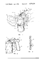
- FIG. 1 is a perspective view which illustrates the attachment of an aerosol can to the operating handle of the invention
- FIG. 2 is a sectional view, partly in elevation, and partly broken away, taken along the lines II--II of FIG. 1;
- FIG. 3 is a sectional view of the container sidewall and fastener assembly taken along the line III--III of FIG. 1;
- FIG. 4 is a perspective view of an operating handle assembly from which the aerosol container has been removed.
- FIG. 5 is an elevation view of the aerosol container mounted within the operating handle of the invention.
- an operating handle assembly 10 is shown in combination with a conventional aerosol spray container of the type commonly used to dispense paint, hair preparations, insecticides, herbicides, disinfectants and the like.
- the aerosol spray container 12 is a sealed cylinder which contains pressurized propellant and an active ingredient.
- the pressurized mixture is discharged through a movable plunger tube 14 which is carried by a plunger head 18.
- the aerosol container is held in one hand with the forefinger of that hand being applied against the plunger head. This is an uncomfortable, awkward position to maintain over an extended duration, and it exposes the hand and fingers to direct contact with the aerosol spray.
- the operating handle assembly 10 includes a hand grip portion 20, a shell portion 22 and a trigger assembly 24 interconnecting the hand grip portion 20 with the shell portion 22.
- the trigger assembly 24 includes a trigger housing 26 and an actuator 28. As can be seen in FIG. 2, the trigger housing 26 encloses a hollow space 30.
- the actuator 28 is received within the hollow space 30 and is mounted for pivotal movement on a pin 32.
- the actuator 28 comprises an actuator arm 34 and a trigger arm 36.
- the trigger arm 36 is angularly offset with respect to the actuator arm 34 whereby movement of the trigger arm toward the hand grip 20 causes a counterclockwise movement of the actuator arm 34 downwardly against the plunger head 18.
- Narrow slots 38, 40 are formed in the trigger housing 26 to allow free movement of the actuator 34 and trigger arm 36.
- the actuator arm 34 projects through the slot 38 and out of the trigger housing 26.
- the terminal portion of the actuator arm 34 is provided with a pad portion 42 which is aligned with the plunger head 18.
- the actuator is rigidly attached to the pivot pin 32, with the ends of the pivot pin 32 defining trunnions, and with the trunnions being rotatably received within sockets formed within the sidewalls of the trigger housing 26.
- the shell 22 is a segment of a cylindrical sidewall and has a height which is slightly in excess of one-half of the height of the aerosol container 12.
- An annular groove 44 is formed along the inside surface of the shell. The purpose of the annular groove 44 is to receive the radially projecting sealing rim 46 which is found on most aerosol containers. The annular rim 46 is received in detented engagement within the annular groove 44 to prevent vertical displacement of the aerosol can 12 after the aerosol container has been placed in the operating position as shown in FIG. 1. This prevents the position of the aerosol container from being disturbed as a result of pressure applied through the actuator arm 34 or as a result of manual shaking movements imparted to the can through the hand grip 20 and trigger housing 26.
- the band clamp assembly 48 includes a flexible band 50 whose ends are coupled together by a quick release overcenter coupling 52.
- the band clamp assembly 48 is coupled to the lower end of the shell 22 by studs 54, 56.
- a rectangular slot 58 is formed in the exterior surface of the shell 22, and the studs 54, 56 are located within the slot and project radially outwardly.
- An eyelet 60 is formed within the flexible band 50 and captures the stud 54 in an interference coupling fit.
- the quick release overcenter coupling fastener 52 provides tight, compressive engagement with the cylindrical sidewall of the aerosol container 12.
- the frictional, compressive engagement of the band clamp assembly with the cylindrical surface of the aerosol container in combination with the detented engagement of the annular sealing rim 46 within the annular groove 44 stabilizes the aerosol container 12 and secures it firmly against the shell 22.
- its aligned operating position will be maintained during operation, and will also be maintained in secure engagement against the shell to permit the can to be shaken without risk of detachment.
- a finger rest 62 is formed along the inside lower end of the hand grip which prevents slipping or sliding movement of the hand along the grip 20 when the aerosol container is being shaken.
- the aerosol container 12 can be quickly inserted into the shell 22 and clamped rigidly into its operating position within the shell, and that the aerosol container can just as easily be removed by releasing the overcenter toggle fastener 52 and allowing the aerosol container to drop downwardly out of the shell 22.
- the shell 22 is coupled to the trigger housing 26 by a shroud panel 64.
- the shroud panel 64 is curved and conforms generally with the curvature of the neck panel 66 which forms the upper end of the aerosol container 12.
- the shroud panel 64 and shell 22 are operable, in combination, for shielding the hand grip 20 with respect to the pressurized aerosol spray 68 which is discharged through the spray jet 16.
- the trigger arm portion 36 of the actuator 28 extends downwardly through the slot 40 and alongside the hand grip 20. As can be seen in FIG. 1, the entire hand may be curled around the hand grip 20 and trigger arm 36 in a comfortable, natural position. According to this arrangement, the handle assembly can be operated over a long application period without finger cramps or discomfort. Additionally, the operating handle assembly 10 is relatively lightweight and is balanced in combination with the aerosol container 12 whereby the operator can apply the aersol spray uniformly in sweeping motions. Additionally, because of the grip of the clamp assembly, the wide operating range of the actuator arm 34, and because of the placement of the annular groove detent structure near the upper end of the shell 22, the handle assembly can accomodate aerosol spray containers of different sizes. Moreover, the spray containers can be attached, operated and released without the use of tools.
- the operating handle assembly 10 is preferably constructed of a lighweight, high strength, durable material such as aluminium or a synthetic polymer material.
Abstract
An operating handle for an aerosol container features a hand grip portion, a shell portion and a trigger assembly interconnecting the hand grip portion and the shell portion. The trigger assembly includes an actuator arm for engaging the plunger head of an aerosol container and a trigger arm projecting along the hand grip portion whereby the trigger arm can be squeezed toward the hand grip portion to drive the actuator arm against the plunger head. The shell portion serves as a receptacle in which the aerosol can is secured and as a shield for isolating the hand and fingers from exposure to the aerosol spray. A quick release fastener assembly is carried by the shell portion for securing the aerosol container in a stable, upright operating position within the shell.
Description
1. Field of the Invention:
The invention relates generally to hand operated appliances and in particular to an operating handle attachment for an aerosol container.
2. Description of the Prior Art
Conventional aerosol spray containers make it possible to apply a variety of spray materials such as paint, hair preparations, insecticides, herbicides, disinfectants and other such materials, some of which may be toxic. According to the usual method of applying a spray material from an aerosol container, the aerosol container is held in one hand with the forefinger of that hand being applied against the plunger head. This procedure exposes the hand and fingers to direct contact with the aerosol spray. The aerosol mixture, as it is discharged through the spray jet, produces an extremely cold spray which causes numbness and discomfort. Additionally, because of the awkward hand position required to operate the plunger head, the forefinger can become cramped during long duration spray applications.
Handle devices are known which attach to various parts of the aerosol can. A trigger mechanism is usually provided in such devices for depressing the plunger head of the aerosol can. However, such handle devices have not provided a comfortable, secure hold onto the aerosol container to permit it to be shaken, from time to time, to keep the aerosol contents mixed for effective delivery by the pressurized propellant. Additionally, none of the conventional handle devices provide a shield structure for preventing the exposure of the operator to the aerosol spray.
A general object of this invention is to provide an operating handle for an aerosol container which will provide for manual operation of the aerosol spray container while shielding the operator from exposure to the aerosol spray material and to avoid exposure of the operator to the extreme cold of the aerosol spray.
Another object of the invention is to provide an operating handle for an aerosol container which provides a stable, secure hold onto the container so that it can be shaken from time to time by hand movement of the operating handle to keep the aerosol contents mixed for effective delivery by the pressurized propellant.
Yet another object of the invention is to provide a lightweight, balanced operating handle for an aerosol spray container which provides a comfortable grip for the operator whereby the operator can apply the aerosol spray uniformly in sweeping motions.
A related object of the invention is to provide an operating handle for an aerosol container having a hand grip and actuating trigger assembly which can be grasped and operated while the hand is in a comfortable, natural position for long duration applications, thereby avoiding finger cramp.
Another object of the invention is to provide an operating handle which can accomodate aerosol spray containers of different sizes, in which the spray container can be attached and operated manually without tools.
An operating handle for an aerosol container features a hand grip portion, a shell portion and a trigger assembly. The trigger assembly includes a housing portion which interconnects the hand grip portion and the shell portion. The trigger assembly includes an actuator arm for engaging the plunger head of an aerosol container and a trigger arm projecting along the hand grip portion whereby the trigger arm can be squeezed toward the hand grip portion to drive the actuator arm against the plunger head. The shell portion serves as a receptacle in which the aerosol can is secured, and as a shield for isolating the hand and fingers from exposure to the aerosol spray. A quick release fastener assembly is carried by the shell portion for securing the aerosol container in a stable upright operating position within the shell.
In the preferred embodiment, the shell portion is a cylindrical sidewall segment having an annular formed along its inside surface. The annular groove receives the annular sealing rim of the aerosol container in detented engagement. A shroud panel interconnects the shell portion and the trigger housing and shields the hand grip with respect to the aerosol spray discharge.
The novel features which characterize the invention are defined by the appended claims. The foregoing and other objects, advantages and features of the invention will hereinafter appear, and for purposes of illustration of the invention, but not of limitation, an exemplary embodiment of the invention is shown in the appended drawings.
FIG. 1 is a perspective view which illustrates the attachment of an aerosol can to the operating handle of the invention;
FIG. 2 is a sectional view, partly in elevation, and partly broken away, taken along the lines II--II of FIG. 1;
FIG. 3 is a sectional view of the container sidewall and fastener assembly taken along the line III--III of FIG. 1;
FIG. 4 is a perspective view of an operating handle assembly from which the aerosol container has been removed; and,
FIG. 5 is an elevation view of the aerosol container mounted within the operating handle of the invention.
In the description which follows, like parts are marked throughout the specification and drawings with the same reference numerals, respectively. The drawings are not necessarily to scale and in some instances proporations have been exaggerated in order to more clearly depict certain features of the invention.
Referring now to FIGS. 1 and 2, an operating handle assembly 10 is shown in combination with a conventional aerosol spray container of the type commonly used to dispense paint, hair preparations, insecticides, herbicides, disinfectants and the like. The aerosol spray container 12 is a sealed cylinder which contains pressurized propellant and an active ingredient. The pressurized mixture is discharged through a movable plunger tube 14 which is carried by a plunger head 18. According to the usual method of dispensing spray material from this type of aerosol container, the aerosol container is held in one hand with the forefinger of that hand being applied against the plunger head. This is an uncomfortable, awkward position to maintain over an extended duration, and it exposes the hand and fingers to direct contact with the aerosol spray.
The operating handle assembly 10 includes a hand grip portion 20, a shell portion 22 and a trigger assembly 24 interconnecting the hand grip portion 20 with the shell portion 22. The trigger assembly 24 includes a trigger housing 26 and an actuator 28. As can be seen in FIG. 2, the trigger housing 26 encloses a hollow space 30. The actuator 28 is received within the hollow space 30 and is mounted for pivotal movement on a pin 32.
The actuator 28 comprises an actuator arm 34 and a trigger arm 36. The trigger arm 36 is angularly offset with respect to the actuator arm 34 whereby movement of the trigger arm toward the hand grip 20 causes a counterclockwise movement of the actuator arm 34 downwardly against the plunger head 18. Narrow slots 38, 40 are formed in the trigger housing 26 to allow free movement of the actuator 34 and trigger arm 36.
The actuator arm 34 projects through the slot 38 and out of the trigger housing 26. The terminal portion of the actuator arm 34 is provided with a pad portion 42 which is aligned with the plunger head 18.
In an alternate mounting arrangement (not illustrated), the actuator is rigidly attached to the pivot pin 32, with the ends of the pivot pin 32 defining trunnions, and with the trunnions being rotatably received within sockets formed within the sidewalls of the trigger housing 26.
Referring now to FIGS. 2, 4 and 5, the shell 22 is a segment of a cylindrical sidewall and has a height which is slightly in excess of one-half of the height of the aerosol container 12. An annular groove 44 is formed along the inside surface of the shell. The purpose of the annular groove 44 is to receive the radially projecting sealing rim 46 which is found on most aerosol containers. The annular rim 46 is received in detented engagement within the annular groove 44 to prevent vertical displacement of the aerosol can 12 after the aerosol container has been placed in the operating position as shown in FIG. 1. This prevents the position of the aerosol container from being disturbed as a result of pressure applied through the actuator arm 34 or as a result of manual shaking movements imparted to the can through the hand grip 20 and trigger housing 26.
Referring now to FIGS. 1, 3 and 4, the aerosol container 12 is secured into the operating position by a band clamp assembly 48. The band clamp assembly 48 includes a flexible band 50 whose ends are coupled together by a quick release overcenter coupling 52. The band clamp assembly 48 is coupled to the lower end of the shell 22 by studs 54, 56. Preferably, a rectangular slot 58 is formed in the exterior surface of the shell 22, and the studs 54, 56 are located within the slot and project radially outwardly. An eyelet 60 is formed within the flexible band 50 and captures the stud 54 in an interference coupling fit.
The quick release overcenter coupling fastener 52 provides tight, compressive engagement with the cylindrical sidewall of the aerosol container 12. The frictional, compressive engagement of the band clamp assembly with the cylindrical surface of the aerosol container in combination with the detented engagement of the annular sealing rim 46 within the annular groove 44 stabilizes the aerosol container 12 and secures it firmly against the shell 22. Thus, its aligned operating position will be maintained during operation, and will also be maintained in secure engagement against the shell to permit the can to be shaken without risk of detachment.
It is necessary to shake the contents of the aerosol container, from time to time, to ensure that the active ingredient is thoroughly mixed with the propellant. A finger rest 62 is formed along the inside lower end of the hand grip which prevents slipping or sliding movement of the hand along the grip 20 when the aerosol container is being shaken.
It is apparent that the aerosol container 12 can be quickly inserted into the shell 22 and clamped rigidly into its operating position within the shell, and that the aerosol container can just as easily be removed by releasing the overcenter toggle fastener 52 and allowing the aerosol container to drop downwardly out of the shell 22.
According to an important feature of the invention, the shell 22 is coupled to the trigger housing 26 by a shroud panel 64. As can best be seen in FIGS. 1 and 5, the shroud panel 64 is curved and conforms generally with the curvature of the neck panel 66 which forms the upper end of the aerosol container 12. The shroud panel 64 and shell 22 are operable, in combination, for shielding the hand grip 20 with respect to the pressurized aerosol spray 68 which is discharged through the spray jet 16.
The trigger arm portion 36 of the actuator 28 extends downwardly through the slot 40 and alongside the hand grip 20. As can be seen in FIG. 1, the entire hand may be curled around the hand grip 20 and trigger arm 36 in a comfortable, natural position. According to this arrangement, the handle assembly can be operated over a long application period without finger cramps or discomfort. Additionally, the operating handle assembly 10 is relatively lightweight and is balanced in combination with the aerosol container 12 whereby the operator can apply the aersol spray uniformly in sweeping motions. Additionally, because of the grip of the clamp assembly, the wide operating range of the actuator arm 34, and because of the placement of the annular groove detent structure near the upper end of the shell 22, the handle assembly can accomodate aerosol spray containers of different sizes. Moreover, the spray containers can be attached, operated and released without the use of tools.
The operating handle assembly 10 is preferably constructed of a lighweight, high strength, durable material such as aluminium or a synthetic polymer material.
The foregoing preferred embodiment of the invention has been shown and described herein for purposes of illustration only. Various changes in the structure as illustrated will no doubt occur to those skilled in the art. Such changes should be understood as being comprehended by the invention insofar as such changes fall within the spirit and scope of the appended claims.
Claims (3)
1. An operating handle for an aerosol container of the type having a tubular sidewall and a plunger head coupled to a dispensing valve for releasing pressurized contents of the aerosol container through a spray jet in response to displacement of the plunger head, said operating handle assembly comprising a hand grip portion, a trigger housing portion connected to the hand grip portion, said trigger housing having an interior chamber for receiving a trigger assembly; a trigger assembly disposed within the interior chamber of said trigger housing, said trigger assembly being pivotally coupled to said trigger housing, and said trigger assembly including an actuator arm for engaging the plunger head of an aerosol container and having a trigger arm projecting externally of said trigger housing and extending along said hand grip portion whereby said trigger arm can be squeezed toward the hand grip portion; a shell portion connected to and depending from said trigger housing, said shell portion being semi-cylindrical and conformed for surface engagement with a portion of the cylindrical sidewall of an aerosol container; fastening means carried by said shell portion for securing an aerosol container in an upright position within said shell with its plunger head aligned for engagement by said actuator arm; and a shroud panel interconnecting said shell portion and, said trigger housing, said shroud panel and said shell portion being operable, in combination, for shielding said hand grip portion with respect to pressurized aerosol spray discharged through a spray jet.
2. An operating handle for an aerosol container of the type having a tubular sidewall, a neck panel portion sealing one end of said aerosol container, and a plunger head extending through said neck panel portion and coupled to a dispensing valve for releasing pressurized contents of the aerosol container through a spray jet in response to displacement of the plunger head, the union of said neck panel portion and said cylindrical sidewall defining a radially projecting rim, said operating handle assembly comprising a hand grip portion, a trigger housing connected to the hand grip portion, said trigger housing having an interior chamber for receiving a trigger assembly; a trigger assembly disposed within the interior chamber of said trigger housing, said trigger assembly being pivotally coupled to said trigger housing, and said trigger assembly including an actuator arm for engaging the plunger head of an aerosol container and having a trigger arm projecting externally of said trigger housing and extending along the hand grip portion whereby said trigger arm can be squeezed toward the hand grip portion; a shell connected to and depending from said trigger housing, said shell having a curved sidewall and an annular groove formed along the inside surface of said curved sidewall segment, said shell portion being semi-cylindrical and conformed for surface engagement with a portion of the cylindrical sidewall of an aerosol container; fastening means carried by said shell for securing an aerosol container in an operational position within said shell wherein said annular rim is received in detented engagement with said annular groove; and, a shroud panel interconnecting said shell and said trigger housing, said shroud panel and said shell being operable, in combination, for shielding said hand grip portion with respect to pressurized aerosol spray discharged through a spray jet.
3. An operating handle for an aerosol container of the type having a tubular sidewall and a plunger head coupled to a dispensing valve for releasing the pressurized contents of the aerosol container through a spray jet in response to displacement of the plunger head, said operating handle assembly comprising a hand grip portion, a trigger housing connected to the hand grip portion, said trigger housing having an interior chamber for receiving a trigger assembly; a trigger assembly disposed within the interior chamber of the trigger housing, said trigger assembly being pivotally coupled to said trigger housing, and said trigger assembly including an actuator arm for engaging the plunger head of an aerosol container and having a trigger arm projecting externally of the trigger housing and extending along said hand grip portion whereby said trigger arm can be squeezed toward the hand grip portion; a shell connected to and depending from said trigger housing; fastening means carried by said shell for securing an aerosol container in an operational position within said shell wherein its plunger head is aligned for engagement with said actuator arm; and, a shroud panel interconnecting said shell and said trigger housing, said shroud panel and said shell being operable, in combination, for shielding said hand grip with respect to the pressurized aerosol spray discharged through said spray jet.
Priority Applications (1)
| Application Number | Priority Date | Filing Date | Title |
|---|---|---|---|
| US06/542,530 US4579258A (en) | 1983-10-17 | 1983-10-17 | Operating handle for aerosol container |
Applications Claiming Priority (1)
| Application Number | Priority Date | Filing Date | Title |
|---|---|---|---|
| US06/542,530 US4579258A (en) | 1983-10-17 | 1983-10-17 | Operating handle for aerosol container |
Publications (1)
| Publication Number | Publication Date |
|---|---|
| US4579258A true US4579258A (en) | 1986-04-01 |
Family
ID=24164226
Family Applications (1)
| Application Number | Title | Priority Date | Filing Date |
|---|---|---|---|
| US06/542,530 Expired - Fee Related US4579258A (en) | 1983-10-17 | 1983-10-17 | Operating handle for aerosol container |
Country Status (1)
| Country | Link |
|---|---|
| US (1) | US4579258A (en) |
Cited By (41)
| Publication number | Priority date | Publication date | Assignee | Title |
|---|---|---|---|---|
| GB2190709A (en) * | 1986-04-04 | 1987-11-25 | Farco | A cap for an aerosol can |
| DE8709222U1 (en) * | 1986-07-14 | 1988-03-24 | Baxenden Scandinavia A/S, Soroe, Dk | |
| US4842158A (en) * | 1988-02-19 | 1989-06-27 | Reyes Jr Ruben | Container handle attachment |
| GB2218471A (en) * | 1988-05-19 | 1989-11-15 | Item Products Ltd | Aerosol can accessory |
| US5400975A (en) * | 1993-11-04 | 1995-03-28 | S. C. Johnson & Son, Inc. | Actuators for electrostatically charged aerosol spray systems |
| FR2724636A1 (en) * | 1994-09-16 | 1996-03-22 | Plastiques De France Ind | Aerosol container spray cap |
| GB2324576A (en) * | 1997-01-07 | 1998-10-28 | Univ Aberdeen | Holder and actuator for dispensing fluid from a container |
| US5839616A (en) * | 1997-08-14 | 1998-11-24 | The Procter & Gamble Company | Blow molded container having pivotal connector for an actuation lever |
| EP0890524A1 (en) * | 1997-07-11 | 1999-01-13 | Adolf Würth GmbH & Co. KG | Holding device for spray can |
| US6016938A (en) * | 1999-05-13 | 2000-01-25 | Eichorst; Lawrence G. | Spray can trigger system |
| US6029862A (en) * | 1998-11-23 | 2000-02-29 | Jones; Myra L. | Selectable rate actuator for spray cans |
| GB2341643A (en) * | 1998-06-17 | 2000-03-22 | James Maguire | Dispensing aid |
| FR2792914A1 (en) * | 1999-04-29 | 2000-11-03 | Plastinel | Control device for aerosol spray comprises handle with front and rear mountings allowing resilient clamping action, lever tipped by clamping mountings causes descent of pushbutton |
| US6551001B2 (en) | 2001-09-14 | 2003-04-22 | S. C. Johnson & Son, Inc. | Cleaning device with a trigger-actuated spray canister |
| US6758412B2 (en) | 2001-09-14 | 2004-07-06 | S.C. Johnson & Son, Inc. | Overcap for use with a cleaning device |
| US20050279767A1 (en) * | 2004-06-01 | 2005-12-22 | Kenny Mark R | Extension handle with control assembly for aerosol cans |
| US7000805B1 (en) * | 2003-11-04 | 2006-02-21 | Chin-Ta Wu | PU foam rubber fluid applicator |
| US20060054634A1 (en) * | 2002-06-26 | 2006-03-16 | Satoshi Mekata | Packaging container for discharge of plurality of contents, packaging product including the packaging container and process for producing the packaging product |
| US20060157499A1 (en) * | 2005-01-18 | 2006-07-20 | Jim Mancel | Apparatus for spray application of a sunless tanning product |
| US20060190615A1 (en) * | 2005-01-21 | 2006-08-24 | Panwar Shivendra S | On demand peer-to-peer video streaming with multiple description coding |
| US20070170205A1 (en) * | 2006-01-24 | 2007-07-26 | Walker Jeffrey T | Extension sprayer |
| US20080110936A1 (en) * | 2006-11-14 | 2008-05-15 | Gotohti Com Inc | Removable lever assembly for fluid dispenser |
| US7686193B1 (en) * | 2007-04-13 | 2010-03-30 | George Gervais | Mechanical actuator for aerosol can |
| US20100096477A1 (en) * | 2008-10-20 | 2010-04-22 | University Of Northern Iowa Research Foundation | Ergonomic Spray Can Adapter and Positioning Apparatus |
| US20100096472A1 (en) * | 2008-10-20 | 2010-04-22 | University Of Northern Iowa Research Foundation | Ergonomic spray can adapter and positioning apparatus |
| US7775401B2 (en) | 2007-06-25 | 2010-08-17 | S.C. Johnson & Son, Inc. | Fluid delivery system for dispensing primary and secondary fluids |
| US7905430B1 (en) * | 2008-01-20 | 2011-03-15 | Kumar Sivathanu B | Spray system |
| US20110226805A1 (en) * | 2010-03-18 | 2011-09-22 | Dispensing Dynamics International | Dispensing system |
| US8272542B2 (en) | 2008-02-29 | 2012-09-25 | Safeworld International Inc. | Spray can handle attachment |
| US8444020B1 (en) | 2010-04-01 | 2013-05-21 | Mark Kenny | Assembly for hand held or remote elevated operation of aerosol spray cans |
| US8500039B2 (en) | 2011-07-25 | 2013-08-06 | Arthur L Allen, Jr. | Remote actuation device for spray cans |
| US8789404B2 (en) | 2009-07-23 | 2014-07-29 | Gkn Sinter Metals, Llc | Compression limiter having retention features |
| US20150203279A1 (en) * | 2012-07-23 | 2015-07-23 | Meadwestvaco Calmar, Inc. | Aerosol actuators, devices, and methods of making and using the same |
| US20190202623A1 (en) * | 2017-12-29 | 2019-07-04 | Fu-Cheng TSAI | Auxiliary clamping operation device for spray can |
| DE202020102815U1 (en) | 2020-05-18 | 2020-06-08 | Domenic Juppenlatz | Adapter for spray cans with propellant gas |
| US10799901B2 (en) | 2018-11-16 | 2020-10-13 | Michael Langsdale | Mountable apparatus for the remote discharge of canisters for posterior skin application |
| DE102020113371A1 (en) | 2020-05-18 | 2021-11-18 | Domenic Juppenlatz | Adapter for spray cans with propellant gas |
| US11369710B2 (en) | 2019-05-16 | 2022-06-28 | Dispensing Dynamics International, Inc. | Fragrance dispensers and methods |
| US20230076652A1 (en) * | 2021-09-08 | 2023-03-09 | Tri Trong Dinh | Hand-operated bottle and container dispensing assistance device and method |
| US20230146584A1 (en) * | 2021-11-09 | 2023-05-11 | Bg Intellectuals, Inc. | Sprayer assembly |
| US20230219739A1 (en) * | 2022-01-12 | 2023-07-13 | Seymour Of Sycamore Inc. | Aerosol can activator |
Citations (14)
| Publication number | Priority date | Publication date | Assignee | Title |
|---|---|---|---|---|
| US2720422A (en) * | 1954-10-05 | 1955-10-11 | Mercur Dave | Device for mounting spray containers |
| FR1117245A (en) * | 1954-12-20 | 1956-05-18 | Improvements to means such as those for controlling the projection of a fluid, in particular in spray form | |
| US2893606A (en) * | 1957-11-19 | 1959-07-07 | Jacob W Hawkins | Actuator for pressurized dispensers |
| US2960260A (en) * | 1959-05-20 | 1960-11-15 | Louis F Kutik | Actuating handle for dispensing cans |
| US3045878A (en) * | 1959-02-02 | 1962-07-24 | Aeroplast Corp | Operating handle for aerosol containers |
| US3112849A (en) * | 1960-06-27 | 1963-12-03 | H H Helbush | Handle device |
| US3229858A (en) * | 1964-06-08 | 1966-01-18 | Gilbert L Lesh | Device for remote operation of pressurized spray can |
| US3229859A (en) * | 1964-10-23 | 1966-01-18 | Frederick M Conroy | Extension tools |
| US3359017A (en) * | 1967-03-01 | 1967-12-19 | Ideal Corp | Pipe coupling of corrugated shield type |
| US3933377A (en) * | 1974-05-30 | 1976-01-20 | Mckenney's, Inc. | Hanger assembly for pipe |
| US4089440A (en) * | 1976-07-01 | 1978-05-16 | Edward Lee | Handle support and operating assembly for aerosol spray cans |
| US4092000A (en) * | 1976-11-22 | 1978-05-30 | Offutt Iii Harry C | Extension spray device |
| US4401240A (en) * | 1981-02-23 | 1983-08-30 | Brack Joe B | Hand held spray can adapter |
| US4413756A (en) * | 1978-12-20 | 1983-11-08 | Kirley Joseph F | Aerosol insect exterminator device |
-
1983
- 1983-10-17 US US06/542,530 patent/US4579258A/en not_active Expired - Fee Related
Patent Citations (14)
| Publication number | Priority date | Publication date | Assignee | Title |
|---|---|---|---|---|
| US2720422A (en) * | 1954-10-05 | 1955-10-11 | Mercur Dave | Device for mounting spray containers |
| FR1117245A (en) * | 1954-12-20 | 1956-05-18 | Improvements to means such as those for controlling the projection of a fluid, in particular in spray form | |
| US2893606A (en) * | 1957-11-19 | 1959-07-07 | Jacob W Hawkins | Actuator for pressurized dispensers |
| US3045878A (en) * | 1959-02-02 | 1962-07-24 | Aeroplast Corp | Operating handle for aerosol containers |
| US2960260A (en) * | 1959-05-20 | 1960-11-15 | Louis F Kutik | Actuating handle for dispensing cans |
| US3112849A (en) * | 1960-06-27 | 1963-12-03 | H H Helbush | Handle device |
| US3229858A (en) * | 1964-06-08 | 1966-01-18 | Gilbert L Lesh | Device for remote operation of pressurized spray can |
| US3229859A (en) * | 1964-10-23 | 1966-01-18 | Frederick M Conroy | Extension tools |
| US3359017A (en) * | 1967-03-01 | 1967-12-19 | Ideal Corp | Pipe coupling of corrugated shield type |
| US3933377A (en) * | 1974-05-30 | 1976-01-20 | Mckenney's, Inc. | Hanger assembly for pipe |
| US4089440A (en) * | 1976-07-01 | 1978-05-16 | Edward Lee | Handle support and operating assembly for aerosol spray cans |
| US4092000A (en) * | 1976-11-22 | 1978-05-30 | Offutt Iii Harry C | Extension spray device |
| US4413756A (en) * | 1978-12-20 | 1983-11-08 | Kirley Joseph F | Aerosol insect exterminator device |
| US4401240A (en) * | 1981-02-23 | 1983-08-30 | Brack Joe B | Hand held spray can adapter |
Cited By (63)
| Publication number | Priority date | Publication date | Assignee | Title |
|---|---|---|---|---|
| GB2190709A (en) * | 1986-04-04 | 1987-11-25 | Farco | A cap for an aerosol can |
| GB2190709B (en) * | 1986-04-04 | 1989-11-22 | Farco | A cap for an aerosol can |
| DE8709222U1 (en) * | 1986-07-14 | 1988-03-24 | Baxenden Scandinavia A/S, Soroe, Dk | |
| US4842158A (en) * | 1988-02-19 | 1989-06-27 | Reyes Jr Ruben | Container handle attachment |
| GB2218471A (en) * | 1988-05-19 | 1989-11-15 | Item Products Ltd | Aerosol can accessory |
| GB2218471B (en) * | 1988-05-19 | 1991-11-20 | Item Products Ltd | Aerosol can accessory |
| US5400975A (en) * | 1993-11-04 | 1995-03-28 | S. C. Johnson & Son, Inc. | Actuators for electrostatically charged aerosol spray systems |
| FR2724636A1 (en) * | 1994-09-16 | 1996-03-22 | Plastiques De France Ind | Aerosol container spray cap |
| GB2324576A (en) * | 1997-01-07 | 1998-10-28 | Univ Aberdeen | Holder and actuator for dispensing fluid from a container |
| EP0890524A1 (en) * | 1997-07-11 | 1999-01-13 | Adolf Würth GmbH & Co. KG | Holding device for spray can |
| US5839616A (en) * | 1997-08-14 | 1998-11-24 | The Procter & Gamble Company | Blow molded container having pivotal connector for an actuation lever |
| GB2341643A (en) * | 1998-06-17 | 2000-03-22 | James Maguire | Dispensing aid |
| GB2341643B (en) * | 1998-06-17 | 2002-07-10 | James Maguire | Dispensing aid |
| US6029862A (en) * | 1998-11-23 | 2000-02-29 | Jones; Myra L. | Selectable rate actuator for spray cans |
| FR2792914A1 (en) * | 1999-04-29 | 2000-11-03 | Plastinel | Control device for aerosol spray comprises handle with front and rear mountings allowing resilient clamping action, lever tipped by clamping mountings causes descent of pushbutton |
| US6016938A (en) * | 1999-05-13 | 2000-01-25 | Eichorst; Lawrence G. | Spray can trigger system |
| US6551001B2 (en) | 2001-09-14 | 2003-04-22 | S. C. Johnson & Son, Inc. | Cleaning device with a trigger-actuated spray canister |
| US6758412B2 (en) | 2001-09-14 | 2004-07-06 | S.C. Johnson & Son, Inc. | Overcap for use with a cleaning device |
| US7455195B2 (en) * | 2002-06-26 | 2008-11-25 | Daizo Co., Ltd. | Container for discharging plural contents, a dispenser using the container, and a process for producing the dispenser |
| US20060054634A1 (en) * | 2002-06-26 | 2006-03-16 | Satoshi Mekata | Packaging container for discharge of plurality of contents, packaging product including the packaging container and process for producing the packaging product |
| AU2003244078B2 (en) * | 2002-06-26 | 2009-05-14 | Daizo Co., Ltd. | Packaging container for discharge of plurality of contents, packaging product including the packaging container and process for producing the packaging product |
| US7000805B1 (en) * | 2003-11-04 | 2006-02-21 | Chin-Ta Wu | PU foam rubber fluid applicator |
| US20050279767A1 (en) * | 2004-06-01 | 2005-12-22 | Kenny Mark R | Extension handle with control assembly for aerosol cans |
| US20060157499A1 (en) * | 2005-01-18 | 2006-07-20 | Jim Mancel | Apparatus for spray application of a sunless tanning product |
| US7594593B2 (en) * | 2005-01-18 | 2009-09-29 | Jim Mancel | Apparatus for spray application of a sunless tanning product |
| US20060190615A1 (en) * | 2005-01-21 | 2006-08-24 | Panwar Shivendra S | On demand peer-to-peer video streaming with multiple description coding |
| US20070170205A1 (en) * | 2006-01-24 | 2007-07-26 | Walker Jeffrey T | Extension sprayer |
| US20080110936A1 (en) * | 2006-11-14 | 2008-05-15 | Gotohti Com Inc | Removable lever assembly for fluid dispenser |
| US7798369B2 (en) * | 2006-11-14 | 2010-09-21 | Gotohti.Com Inc. | Removable lever assembly for fluid dispenser |
| US7686193B1 (en) * | 2007-04-13 | 2010-03-30 | George Gervais | Mechanical actuator for aerosol can |
| US7997449B2 (en) | 2007-06-25 | 2011-08-16 | S.C. Johnson & Son, Inc. | Fluid delivery system for dispensing primary and secondary fluids |
| US7775401B2 (en) | 2007-06-25 | 2010-08-17 | S.C. Johnson & Son, Inc. | Fluid delivery system for dispensing primary and secondary fluids |
| US20100206903A1 (en) * | 2007-06-25 | 2010-08-19 | Banco Michael J | Fluid delivery system for dispensing primary and secondary fluids |
| US7905430B1 (en) * | 2008-01-20 | 2011-03-15 | Kumar Sivathanu B | Spray system |
| US8272542B2 (en) | 2008-02-29 | 2012-09-25 | Safeworld International Inc. | Spray can handle attachment |
| US20100096477A1 (en) * | 2008-10-20 | 2010-04-22 | University Of Northern Iowa Research Foundation | Ergonomic Spray Can Adapter and Positioning Apparatus |
| US8596553B2 (en) | 2008-10-20 | 2013-12-03 | The Lasercan Company, Llc | Ergonomic spray can adapter and positioning apparatus |
| US20100096472A1 (en) * | 2008-10-20 | 2010-04-22 | University Of Northern Iowa Research Foundation | Ergonomic spray can adapter and positioning apparatus |
| US8453944B2 (en) | 2008-10-20 | 2013-06-04 | The Lasercan Company, Llc | Ergonomic spray can adapter and positioning apparatus |
| US9382930B2 (en) | 2009-07-23 | 2016-07-05 | Gkn Sinter Metals, Llc | Compression limiter with retention features |
| US8789404B2 (en) | 2009-07-23 | 2014-07-29 | Gkn Sinter Metals, Llc | Compression limiter having retention features |
| US8573447B2 (en) * | 2010-03-18 | 2013-11-05 | Dispensing Dynamics International | Dispensing system |
| US20110226805A1 (en) * | 2010-03-18 | 2011-09-22 | Dispensing Dynamics International | Dispensing system |
| US9156603B1 (en) | 2010-03-18 | 2015-10-13 | Dispensing Dynamics International | Dispensing System |
| US8444020B1 (en) | 2010-04-01 | 2013-05-21 | Mark Kenny | Assembly for hand held or remote elevated operation of aerosol spray cans |
| WO2012125205A1 (en) | 2011-03-17 | 2012-09-20 | Dispensing Dynamics International | Dispensing system |
| EP2686267A4 (en) * | 2011-03-17 | 2015-08-12 | Dispensing Dynamics Int | Dispensing system |
| US8500039B2 (en) | 2011-07-25 | 2013-08-06 | Arthur L Allen, Jr. | Remote actuation device for spray cans |
| US20150203279A1 (en) * | 2012-07-23 | 2015-07-23 | Meadwestvaco Calmar, Inc. | Aerosol actuators, devices, and methods of making and using the same |
| US9889982B2 (en) * | 2012-07-23 | 2018-02-13 | Silgan Dispensing Systems Corporation | Aerosol actuators, devices, and methods of making and using the same |
| US10358280B2 (en) | 2012-07-23 | 2019-07-23 | Silgan Dispensing Systems Corporation | Aerosol actuators, devices and methods of making and using the same |
| US20190202623A1 (en) * | 2017-12-29 | 2019-07-04 | Fu-Cheng TSAI | Auxiliary clamping operation device for spray can |
| US10799901B2 (en) | 2018-11-16 | 2020-10-13 | Michael Langsdale | Mountable apparatus for the remote discharge of canisters for posterior skin application |
| US11369710B2 (en) | 2019-05-16 | 2022-06-28 | Dispensing Dynamics International, Inc. | Fragrance dispensers and methods |
| US11857704B2 (en) | 2019-05-16 | 2024-01-02 | Dispensing Dynamics International, Inc. | Fragrance dispensers and methods |
| DE202020102815U1 (en) | 2020-05-18 | 2020-06-08 | Domenic Juppenlatz | Adapter for spray cans with propellant gas |
| DE102020113371B4 (en) | 2020-05-18 | 2021-11-25 | Domenic Juppenlatz | Adapter for spray cans with propellant gas |
| DE102020113371A1 (en) | 2020-05-18 | 2021-11-18 | Domenic Juppenlatz | Adapter for spray cans with propellant gas |
| US20230076652A1 (en) * | 2021-09-08 | 2023-03-09 | Tri Trong Dinh | Hand-operated bottle and container dispensing assistance device and method |
| US11731828B2 (en) * | 2021-09-08 | 2023-08-22 | Tri Trong Dinh | Hand-operated bottle and container dispensing assistance device and method |
| US20230146584A1 (en) * | 2021-11-09 | 2023-05-11 | Bg Intellectuals, Inc. | Sprayer assembly |
| US11912491B2 (en) * | 2021-11-09 | 2024-02-27 | Bg Intellectuals, Inc. | Sprayer assembly |
| US20230219739A1 (en) * | 2022-01-12 | 2023-07-13 | Seymour Of Sycamore Inc. | Aerosol can activator |
Similar Documents
| Publication | Publication Date | Title |
|---|---|---|
| US4579258A (en) | Operating handle for aerosol container | |
| US6338422B1 (en) | Actuation device for manually operated pump sprayer | |
| US2868421A (en) | Attachment for spray containers | |
| US5755363A (en) | Device for dispensing a flowable mass stored under pressure in a container | |
| US5141348A (en) | Paste wax applicator | |
| US4401240A (en) | Hand held spray can adapter | |
| US3734357A (en) | Portable holder for pressurized containers | |
| US4092000A (en) | Extension spray device | |
| US5992707A (en) | Nozzle actuator | |
| CA2278669C (en) | Spray can actuator with enhanced attachment mechanism | |
| US6390333B1 (en) | Illuminating pistol-type device for a plunger actuated aerosol can | |
| JP2000085825A (en) | Assembly for application of liquid or solid product | |
| US3108590A (en) | Combination aerosol, container and applicator | |
| US5992708A (en) | Actuator nozzle | |
| US7686193B1 (en) | Mechanical actuator for aerosol can | |
| US6932247B2 (en) | Gripping device for flexible bag dispenser | |
| HUT68776A (en) | Actuator and hood for dispensing device | |
| US3611820A (en) | Spray-valve-actuating device | |
| US3785568A (en) | Particulate material distributing means | |
| US3973853A (en) | Hand held aerosol can application | |
| US3318493A (en) | Handle and actuating device for attachment to aerosol containers | |
| EP1182148B1 (en) | Accessory for aerosol containers | |
| US20060071036A1 (en) | Mechanical actuator arm for aerosol can | |
| US3122324A (en) | Spraying mechanism | |
| US3276699A (en) | Device for dispensing pressurized material |
Legal Events
| Date | Code | Title | Description |
|---|---|---|---|
| FEPP | Fee payment procedure |
Free format text: PAYOR NUMBER ASSIGNED (ORIGINAL EVENT CODE: ASPN); ENTITY STATUS OF PATENT OWNER: SMALL ENTITY |
|
| REMI | Maintenance fee reminder mailed | ||
| LAPS | Lapse for failure to pay maintenance fees | ||
| STCH | Information on status: patent discontinuation |
Free format text: PATENT EXPIRED DUE TO NONPAYMENT OF MAINTENANCE FEES UNDER 37 CFR 1.362 |
|
| FP | Lapsed due to failure to pay maintenance fee |
Effective date: 19900401 |