US4567879A - Prismatic solar beam concentrator - Google Patents
Prismatic solar beam concentrator Download PDFInfo
- Publication number
- US4567879A US4567879A US06/718,667 US71866785A US4567879A US 4567879 A US4567879 A US 4567879A US 71866785 A US71866785 A US 71866785A US 4567879 A US4567879 A US 4567879A
- Authority
- US
- United States
- Prior art keywords
- angular
- tube
- prisms
- prismatic
- faces
- Prior art date
- Legal status (The legal status is an assumption and is not a legal conclusion. Google has not performed a legal analysis and makes no representation as to the accuracy of the status listed.)
- Expired - Fee Related
Links
Images
Classifications
-
- F—MECHANICAL ENGINEERING; LIGHTING; HEATING; WEAPONS; BLASTING
- F24—HEATING; RANGES; VENTILATING
- F24S—SOLAR HEAT COLLECTORS; SOLAR HEAT SYSTEMS
- F24S23/00—Arrangements for concentrating solar-rays for solar heat collectors
- F24S23/10—Prisms
-
- Y—GENERAL TAGGING OF NEW TECHNOLOGICAL DEVELOPMENTS; GENERAL TAGGING OF CROSS-SECTIONAL TECHNOLOGIES SPANNING OVER SEVERAL SECTIONS OF THE IPC; TECHNICAL SUBJECTS COVERED BY FORMER USPC CROSS-REFERENCE ART COLLECTIONS [XRACs] AND DIGESTS
- Y02—TECHNOLOGIES OR APPLICATIONS FOR MITIGATION OR ADAPTATION AGAINST CLIMATE CHANGE
- Y02E—REDUCTION OF GREENHOUSE GAS [GHG] EMISSIONS, RELATED TO ENERGY GENERATION, TRANSMISSION OR DISTRIBUTION
- Y02E10/00—Energy generation through renewable energy sources
- Y02E10/40—Solar thermal energy, e.g. solar towers
Definitions
- Prior art includes the Prismatic Wall Heater, U.S. Pat. No. 4,527,546 dated 7/9/85 by this inventor.
- This heater has an equilateral double prism No. 1 and equilateral double prism No. 2 mounted on a roof and projecting a concentrated sheet beam through a cavity in a wall to a metal baseboard plate at the bottom of the wall.
- Concurrent art includes the Prismatic Beam Concentrator, Ser. No. 661,988 dated 10/18/84 by this inventor. This concentrator is identical to the concentrator disclosed in this application.
- Concurrent art also includes the Expansion Flow Tube, Ser. No. 730,919 filed 5/6/85 by this inventor. This tube is much shorter than the tube which will be used in practice.
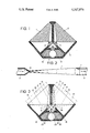
- FIG. 1 is an elevation of the prismatic solar beam concentrator with the prisms shown in section.
- FIG. 2 is a longitudinal section of the expansion flow tube.
- FIG. 3 is an elevation of the prismatic solar beam concentrator with a ray diagram.
- FIG. 1 is an elevation of the prismatic solar beam concentrator showing equilateral double prisms No. One 1 and 2 mounted above equilateral double prisms No. Two 3, 4 and 5 inside housing 6, with the expansion flow tube 7 mounted below prism 5 and packed in insulation 8.
- FIG. 2 is a longitudinal section of the expansion flow tube comprising a straight elongate conical tube 7 with inlet orifice 10 of minimum diameter (5 mm), outlet orifice 11 of maximum diameter (25 mm) and copper tubing 12.
- a short tube with an exaggerated angle of deflection off the interior wall is shown in order to better illustrate the mechanics of flow (horizontal arrows), expansion (vertical arrows) and deflection in the direction of flow.
- the beam concentrator and flow tube will be 6 meters (20 feet) or more in length.
- FIG. 3 is an elevation of the prismatic solar beam concentrator with a ray diagram.
- Two convergent rectangular incipient beams 13 of diffused sunlight are received and transmitted by planar faces 14 and refracted by angular wedge faces 15 of prisms 1 and 2, forming two concentrated convergent rectangular beams 16.
- Beams 16 are transmitted by angular wedge faces 17 and refracted by angular V-groove faces 18 of prisms 3 and 4, forming two concentrated convergent sheet beams 19.
- the prismatic planes of prisms 1, 2, 3 and 4 are inclined 42.5° from the vertical plane.
- Beams 19 are transmitted by angular wedge faces 20 and refracted by angular V-groove faces 21 of prism 5, forming concentrated sheet beam 22 which is emitted in the vertical prismatic plane onto the exterior wall of expansion tube 7.
- each refraction reduces the beam width by a factor of 0.1414.
- the factor of total reduction of width of incipient beams 13 is 0.0028, as follows;
Landscapes
- Engineering & Computer Science (AREA)
- Physics & Mathematics (AREA)
- Life Sciences & Earth Sciences (AREA)
- Sustainable Development (AREA)
- Sustainable Energy (AREA)
- Thermal Sciences (AREA)
- Chemical & Material Sciences (AREA)
- Combustion & Propulsion (AREA)
- Mechanical Engineering (AREA)
- General Engineering & Computer Science (AREA)
- Cyclones (AREA)
Abstract
A prismatic beam concentrator comprising two equilateral double prisms No. 1 and three equilateral double prisms No. 2 mounted above an expansion flow tube. The prisms receive two convergent incipient beams of diffused sunlight and emit a concentrated sheet beam onto the exterior wall of the expansion flow tube. An expansion flow tube is a straight elongate conical tube with an inlet orifice of minimum diameter (5 mm) and an outlet orifice of maximum diameter (25 mm). Water circulating through the tube is heated by the concentrated sheet beam. The warm water expands outward against the interior wall of the tube and deflects toward the outlet orifice, which is the direction of flow. The deflection of water in the direction of flow increases the rate of flow and decreases the pressure that need be applied by the pump.
Description
Prior art includes the Prismatic Wall Heater, U.S. Pat. No. 4,527,546 dated 7/9/85 by this inventor. This heater has an equilateral double prism No. 1 and equilateral double prism No. 2 mounted on a roof and projecting a concentrated sheet beam through a cavity in a wall to a metal baseboard plate at the bottom of the wall.
Concurrent art includes the Prismatic Beam Concentrator, Ser. No. 661,988 dated 10/18/84 by this inventor. This concentrator is identical to the concentrator disclosed in this application.
Concurrent art also includes the Expansion Flow Tube, Ser. No. 730,919 filed 5/6/85 by this inventor. This tube is much shorter than the tube which will be used in practice.
FIG. 1 is an elevation of the prismatic solar beam concentrator with the prisms shown in section.
FIG. 2 is a longitudinal section of the expansion flow tube.
FIG. 3 is an elevation of the prismatic solar beam concentrator with a ray diagram.
FIG. 1 is an elevation of the prismatic solar beam concentrator showing equilateral double prisms No. One 1 and 2 mounted above equilateral double prisms No. Two 3, 4 and 5 inside housing 6, with the expansion flow tube 7 mounted below prism 5 and packed in insulation 8.
FIG. 2 is a longitudinal section of the expansion flow tube comprising a straight elongate conical tube 7 with inlet orifice 10 of minimum diameter (5 mm), outlet orifice 11 of maximum diameter (25 mm) and copper tubing 12. A short tube with an exaggerated angle of deflection off the interior wall is shown in order to better illustrate the mechanics of flow (horizontal arrows), expansion (vertical arrows) and deflection in the direction of flow. In practice the beam concentrator and flow tube will be 6 meters (20 feet) or more in length.
FIG. 3 is an elevation of the prismatic solar beam concentrator with a ray diagram. Two convergent rectangular incipient beams 13 of diffused sunlight are received and transmitted by planar faces 14 and refracted by angular wedge faces 15 of prisms 1 and 2, forming two concentrated convergent rectangular beams 16.
Beams 16 are transmitted by angular wedge faces 17 and refracted by angular V-groove faces 18 of prisms 3 and 4, forming two concentrated convergent sheet beams 19.
The prismatic planes of prisms 1, 2, 3 and 4 are inclined 42.5° from the vertical plane.
Each refraction reduces the beam width by a factor of 0.1414. There are three refractions, so the factor of total reduction of width of incipient beams 13 is 0.0028, as follows;
Incipient beam width ×0.0028 =concentrated beam width 200 mm×0.0028 =0.56 mm
Claims (1)
1. A prismatic solar beam concentrator comprising;
a. two equilateral double prisms (1,2), each having a planar face (14) and two angular wedge faces (15), with the prismatic plane bisecting the planar face (14) and the edge formed by the junction of the two angular wedge faces (15) being inclined 42.5° from the vertical plane,
b. two equilateral double prisms (3,4) mounted below prisms (1,2), each having two angular wedge faces (17) and two angular V-groove faces (18), with the prismatic plane bisecting the edges formed by the junction of the two angular wedge faces (17) and the junction of the two angular V-groove faces (18) being inclined 42.5° from the vertical plane,
c. an equilateral double prism (5) mounted below prisms (3,4) and having two angular wedge faces (20) and two angular V-groove faces (21), with the prismatic plane bisecting the edges formed by the junction of the two angular wedge faces (20) and the junction of the two angular V-groove faces (21) occupying the vertical plane, and
d. an expansion flow tube mounted below the equilateral double prism (5) and comprising a straight elongate conical tube (7) with an inlet orifice (10) of minimum diameter and an outlet orifice (11) of maximum diameter.
Priority Applications (1)
| Application Number | Priority Date | Filing Date | Title |
|---|---|---|---|
| US06/718,667 US4567879A (en) | 1985-04-01 | 1985-04-01 | Prismatic solar beam concentrator |
Applications Claiming Priority (1)
| Application Number | Priority Date | Filing Date | Title |
|---|---|---|---|
| US06/718,667 US4567879A (en) | 1985-04-01 | 1985-04-01 | Prismatic solar beam concentrator |
Publications (1)
| Publication Number | Publication Date |
|---|---|
| US4567879A true US4567879A (en) | 1986-02-04 |
Family
ID=24886993
Family Applications (1)
| Application Number | Title | Priority Date | Filing Date |
|---|---|---|---|
| US06/718,667 Expired - Fee Related US4567879A (en) | 1985-04-01 | 1985-04-01 | Prismatic solar beam concentrator |
Country Status (1)
| Country | Link |
|---|---|
| US (1) | US4567879A (en) |
Cited By (4)
| Publication number | Priority date | Publication date | Assignee | Title |
|---|---|---|---|---|
| US4610518A (en) * | 1984-12-14 | 1986-09-09 | Clegg John E | Involute beam concentrator |
| US4632092A (en) * | 1986-05-08 | 1986-12-30 | Clegg John E | Inset solar prism |
| US4967730A (en) * | 1989-11-16 | 1990-11-06 | Ventus, Inc. | Constant absorption solar furnace |
| US5159188A (en) * | 1990-08-14 | 1992-10-27 | Sony Corporation | Optical reception apparatus using prism having caldera-shaped concave portion |
Citations (8)
| Publication number | Priority date | Publication date | Assignee | Title |
|---|---|---|---|---|
| FR696M (en) * | 1960-10-05 | 1961-07-24 | ||
| US3547526A (en) * | 1967-10-26 | 1970-12-15 | Kollsman Instr Corp | Optical beam cross-section converter |
| GB2041506A (en) * | 1979-02-06 | 1980-09-10 | Wu Shing Hsiung | Solar lighting system |
| US4267826A (en) * | 1978-06-20 | 1981-05-19 | Dale C. Miller | Solar collector for heating and cooling |
| JPS5721749A (en) * | 1980-07-14 | 1982-02-04 | Hitachi Ltd | Solar heat collector |
| US4337759A (en) * | 1979-10-10 | 1982-07-06 | John M. Popovich | Radiant energy concentration by optical total internal reflection |
| GB2100415A (en) * | 1981-06-15 | 1982-12-22 | Subryan Neville Anthony | Solar heaters |
| US4492439A (en) * | 1982-03-15 | 1985-01-08 | Clegg John E | Monochromatic beam concentrator |
-
1985
- 1985-04-01 US US06/718,667 patent/US4567879A/en not_active Expired - Fee Related
Patent Citations (8)
| Publication number | Priority date | Publication date | Assignee | Title |
|---|---|---|---|---|
| FR696M (en) * | 1960-10-05 | 1961-07-24 | ||
| US3547526A (en) * | 1967-10-26 | 1970-12-15 | Kollsman Instr Corp | Optical beam cross-section converter |
| US4267826A (en) * | 1978-06-20 | 1981-05-19 | Dale C. Miller | Solar collector for heating and cooling |
| GB2041506A (en) * | 1979-02-06 | 1980-09-10 | Wu Shing Hsiung | Solar lighting system |
| US4337759A (en) * | 1979-10-10 | 1982-07-06 | John M. Popovich | Radiant energy concentration by optical total internal reflection |
| JPS5721749A (en) * | 1980-07-14 | 1982-02-04 | Hitachi Ltd | Solar heat collector |
| GB2100415A (en) * | 1981-06-15 | 1982-12-22 | Subryan Neville Anthony | Solar heaters |
| US4492439A (en) * | 1982-03-15 | 1985-01-08 | Clegg John E | Monochromatic beam concentrator |
Cited By (4)
| Publication number | Priority date | Publication date | Assignee | Title |
|---|---|---|---|---|
| US4610518A (en) * | 1984-12-14 | 1986-09-09 | Clegg John E | Involute beam concentrator |
| US4632092A (en) * | 1986-05-08 | 1986-12-30 | Clegg John E | Inset solar prism |
| US4967730A (en) * | 1989-11-16 | 1990-11-06 | Ventus, Inc. | Constant absorption solar furnace |
| US5159188A (en) * | 1990-08-14 | 1992-10-27 | Sony Corporation | Optical reception apparatus using prism having caldera-shaped concave portion |
Similar Documents
| Publication | Publication Date | Title |
|---|---|---|
| US4723535A (en) | Solar trap | |
| US4505264A (en) | Electromagnetic wave concentrator | |
| DE69519480T2 (en) | SUBMERSIBLE PIPE | |
| US4567879A (en) | Prismatic solar beam concentrator | |
| US4162824A (en) | Nonimaging radiant energy collector and concentrator | |
| US4142510A (en) | Solar heater | |
| US4215676A (en) | Frame arms for solar collector | |
| GB910266A (en) | Flow cell | |
| US4201194A (en) | Solar heat collector with channeled panel | |
| GB1492916A (en) | Fluid conduit | |
| US4598696A (en) | Black-water solar panel | |
| GB1138015A (en) | Improvements in expansion joints for piping systems | |
| FR2269038A1 (en) | Solar heating system using modular blocks - has compartment for pipe connections next to reflector and tube compartment | |
| US4527546A (en) | Prismatic wall heater | |
| US4610518A (en) | Involute beam concentrator | |
| RU2154778C1 (en) | Solar photoelectric module with concentrator | |
| FR2312742A1 (en) | Dwelling house heating system utilising solar energy - has southerly aligned angled roof section to allow passage of radiation | |
| US4141340A (en) | Solar energy collector | |
| US4632092A (en) | Inset solar prism | |
| SU1571371A1 (en) | Panel of building for use of solar energy | |
| KR810001084Y1 (en) | Solar heat absorption plate for heating water | |
| US4621908A (en) | Monochromatic beam concentrator | |
| RU2085683C1 (en) | Building | |
| SU1032231A1 (en) | Diffusion pump | |
| SU1474393A1 (en) | Solar energy collector |
Legal Events
| Date | Code | Title | Description |
|---|---|---|---|
| REMI | Maintenance fee reminder mailed | ||
| LAPS | Lapse for failure to pay maintenance fees | ||
| STCH | Information on status: patent discontinuation |
Free format text: PATENT EXPIRED DUE TO NONPAYMENT OF MAINTENANCE FEES UNDER 37 CFR 1.362 |
|
| FP | Lapsed due to failure to pay maintenance fee |
Effective date: 19900204 |