US4563702A - Video signal scrambling and descrambling systems - Google Patents
Video signal scrambling and descrambling systems Download PDFInfo
- Publication number
- US4563702A US4563702A US06/498,875 US49887583A US4563702A US 4563702 A US4563702 A US 4563702A US 49887583 A US49887583 A US 49887583A US 4563702 A US4563702 A US 4563702A
- Authority
- US
- United States
- Prior art keywords
- video information
- lines
- scrambled
- stored
- line
- Prior art date
- Legal status (The legal status is an assumption and is not a legal conclusion. Google has not performed a legal analysis and makes no representation as to the accuracy of the status listed.)
- Expired - Lifetime
Links
Images


Classifications
-
- H—ELECTRICITY
- H04—ELECTRIC COMMUNICATION TECHNIQUE
- H04N—PICTORIAL COMMUNICATION, e.g. TELEVISION
- H04N7/00—Television systems
- H04N7/16—Analogue secrecy systems; Analogue subscription systems
- H04N7/167—Systems rendering the television signal unintelligible and subsequently intelligible
- H04N7/169—Systems operating in the time domain of the television signal
- H04N7/1696—Systems operating in the time domain of the television signal by changing or reversing the order of active picture signal portions
-
- H—ELECTRICITY
- H04—ELECTRIC COMMUNICATION TECHNIQUE
- H04N—PICTORIAL COMMUNICATION, e.g. TELEVISION
- H04N7/00—Television systems
- H04N7/16—Analogue secrecy systems; Analogue subscription systems
- H04N7/167—Systems rendering the television signal unintelligible and subsequently intelligible
- H04N7/1675—Providing digital key or authorisation information for generation or regeneration of the scrambling sequence
-
- H—ELECTRICITY
- H04—ELECTRIC COMMUNICATION TECHNIQUE
- H04N—PICTORIAL COMMUNICATION, e.g. TELEVISION
- H04N7/00—Television systems
- H04N7/16—Analogue secrecy systems; Analogue subscription systems
- H04N7/167—Systems rendering the television signal unintelligible and subsequently intelligible
- H04N7/169—Systems operating in the time domain of the television signal
Definitions
- the present invention generally pertains to video signal processing and is particularly directed to improved video signal scrambling and descrambling systems.
- video information is scrambled by storing a video information line in a memory and then forming a scrambled video information line by retrieving the video information from the memory in a sequence different from the sequence within the line in which the information was stored.
- the portion at the beginning position of the stored video information line is retrieved at the last position of the scrambled video information line and the portion at the last position of the stored video information line is retrieved at the beginning position of the scrambled video information line.
- the respective lengths of the retrieved portions are varied from one line to the next in response to a randomly generated coded control signal.
- the present invention provides more complex scrambled video signal line formation and thereby better scrambles the video signal.
- the present invention provides a system for scrambling video information lines.
- the scrambling system includes a memory; a storage system for sequentially storing groups of a plural predetermined number of the video information lines in the memory; and a retrieval system for forming a corresponding number of scrambled video information lines by retrieving the stored video information from the memory in a sequence different from the sequence within the stored group in which the information was stored.
- the retrieval system forms the scrambled video information lines by retrieving a portion of a first stored video information line from a first position therein to form a portion of a first scrambled video information line occupying a second position therein; retrieving a portion of the first stored video information line from the corresponding second position therein to form a portion of a second scrambled video information line occupying a position therein other than the corresponding second position; and forming the portion of the first scrambled video information line occupying the corresponding first position therein by retrieving a portion of a stored video information line other than the first stored video information line from a position therein other than the corresponding first position.
- the retrieval system varies the sequence of formation of the scrambled lines from one retrieved group to the next; and the retrieval system also varies the combinations of stored video information lines within the stored groups for forming the first and second scrambled video information lines from one group to the next.
- the retrieval system controls the formation of the scrambled lines in response to a keystream.
- Each frame of the keystream includes a first set of control bits for designating combinations of stored video information lines as sources for corresponding combinations of scrambled video information lines in the formed group, and a second set of control bits for designating the sequence of formation of the scrambled video information lines in the formed group.
- the keystream further includes a third set of control bits for designating the respective lengths of the retrieved portions in each combination of stored video information lines in response to which, the respective lengths are varied from one combination to the next by the retrieval system.
- the present invention provides a system for descrambling scrambled video information lines.
- the system includes a memory; a storage system for sequentially storing groups of a plural predetermined number of the scrambled video information lines in the memory; and a retrieval system for sequentially forming groups of a corresponding number of descrambled video information lines by retrieving the stored video information from the memory in a sequence different from the sequence within the stored group in which the information was stored.
- the retrieval system forms the descrambled video information lines by retrieving a portion of a first scrambled video information line from a first position therein to form a portion of a first descrambled video information line occupying a second position therein; retrieving a portion of the first scrambled video information line from the corresponding second position therein to form a portion of a second descrambled video information line occupying a position therein other than the corresponding second position, and forming the portion of the first descrambled video information line occupying the corresponding first position therein by retrieving a portion of a scrambled video information line other than the first scrambled video information line from a position therein other than the corresponding first position.
- the retrieval system controls the formation of the descrambled lines in response to a keystream.
- Each frame of the keystream includes a first set of control bits for designating combinations of descrambled video information lines as destinations for information stored in corresponding combinations of scrambled video information lines in the stored group.
- the keystream that is used for descrambling the scrambled video information signal is identical to the keystream that is used for scrambling the original video information signal. Accordingly, the keystream preferably further includes a second set of control bits for designating the sequence of retrieval of information from the scrambled video information lines in the stored group and a third set of control bits for designating the respective lengths of the retrieved portions in the combinations of descrambled video information lines.
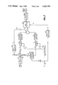
- FIG. 1 is a block diagram of a video signal scrambling system in accordance with the present invention.
- FIG. 2 is a diagram showing an explemplary relationship between stored video signal lines, scrambled video signal lines and descrambled video signal lines.
- FIG. 3 is a block diagram of the waveshaping filler included in the video processor of FIG. 2.
- FIGS. 4a, 4b and 4c illustrates the waveforms of various lines of the unscrambled and scrambled video signals.
- FIG. 5 is a block diagram of a video signal descrambling system in accordance with the present invention.
- FIG. 6 is a block diagram of the sync detection circuit included in the system of FIG. 5.
- the preferred embodiment of the video scrambling system includes a control processor 48, an audio processor 49, a video amplifier 50, a sync detection circuit 51, an analog-to-digital (A/D) converter 52, a video line buffer memory 53, address counters 54, an address FIFO (first-in/first-out) queue 55, a line buffer controller 56, a wave shaping filter 57, a burst generator 58, a sync generator 59, a reference pattern generator 60, a multiplier (MUX) 61 and a digital-to-analog (D/A) converter 62.
- the operation of the control processor 48 is controlled by control signals provided on line 20 by a control computer (not shown).
- a video signal on line 45 is scrambled by the video scrambling system of FIG. 2 in accordance with one portion of each frame of a unique received keystream on line 44 from a scrambler key distribution system (not shown).
- the scrambler key distribution system is described in the aforementioned patent application by Gilhousen et al, the entire disclosure of which is incorporated herein by reference thereto.
- the video amplifier 50 amplifies the video signal on line 45 and filters the same to remove any extraneous or harmonic signals.
- the amplified and filtered video signal is provided on line 63 to the A/D converter 52 and the sync detection circuit 51.
- the sync detection circuit 51 detects the vertical and horizontal synchronization signals in the video signal on line 63 and responds thereto by providing synchronization control and clocking signals on lines 64 to the control processor 48.
- Among these clocking signals is a 14.32 MHz signal, which is at four times the color subcarrier frequency of an NTSC video signal, and which is also provided by the sync detection circuit 51 on line 64a to clock the A/D converter 52.
- the A/D converter 52 converts the amplified video signal on line 63 into a digital video information signal on line 65 at the sampling rate of 14.32 MHz to provide 910 8-bit samples per video line.
- the active video information corresponds to the 744 samples in each line.
- the video line buffer memory 53 stores the digital video signal on line 65 in four groups of four video information lines each. Each stored video information line includes 744 8-bit samples of active video information. A first group includes four consecutive odd-numbered lines from the same video field. A second group includes the next four consecutive odd numbered lines from the same video field. A third group includes four consecutive even-numbered lines from the same video field, and the fourth group includes the next four consecutive even-numbered lines from the same video field. One group of odd-numbered lines is stored in the memory 53 while the information from the previously-stored group of odd-numbered lines is retrieved from the memory 53 to form a four-line group of odd-numbered scrambled video information lines on line 66.
- one group of even-numbered lines is stored in the memory 53 while the information from the previously stored group of even-numbered lines is retrieved from the memory to form a four-line group of even-numbered scrambled video information lines on line 66.
- Video scrambling is accomplished by retrieving the active video information from the memory in a sequence different from that in which it was stored.
- the address counters 54 provide the respective addresses on line 67 to the memory 53 for storing and retrieving video information. These addresses are provided to the address counters 54 on line 68 via the address FIFO queue 55 and line 69 from the control processor 48 in accordance with the unique keystream provided to the control processor 48 on line 44.
- the line buffer controller 56 provides clocking and control signals on lines 70 for synchronizing the operations of the address FIFO queue 55, the address counters 54 and the memory 53 in accordance with clocking and synchronization control signals provided on line 71 by the control processor 48.
- the control processor 48 provides the clocking and synchronization control signals on lines 71 in response to the clocking and synchronization control signals received on lines 64 from the sync detection circuit 51.
- FIG. 2 illustrates an exemplary embodiment of scrambling video information in accordance with the present invention. Scrambling is accomplished within four-line groups. Two control bits of the keystream on line 44 designate which lines within a given, stored four-line group are to be paired for forming a corresponding pair of scrambled video information lines. In the embodiment of FIG. 2, lines 1 and 4 make up one pair in the stored group and the other pair in the stored group is made up of lines 2 and 3. Although each stored active video information line actually contains sixty-two twelve-sample segments, in FIG. 2 each stored line is shown as having only eight segments for simplicity of illustration. In the example of FIG. 2, the segments of stored line 1 are designated "a" through “h”, and the segments of stored line 4 are designated "m” through “t”. The relative lengths of the retrieved portions in each pair of scrambled lines is designated by six control bits in the keystream, which indicate a cutpoint "X" as being after a given number of segments from the beginning of the line.
- control processor 48 is programmed to provide retrieval addresses on line 69 to the address FIFO queue 55 in such a sequence that (a) the left portion on one line of a corresponding scrambled pair is retrieved from the right portion of one line of a designated stored pair; (b) the right portion of the one line of the corresponding scrambled pair is retrieved from the left portion of the other line of the designated stored pair; (c) the left portion of the other line of the corresponding scrambled pair is retrieved from the right portion of the other line of the designated stored pair; and (d) the right portion of the other line of the corresponding scrambled pair is retrieved from the left portion of the one line of the designated stored pair.
- the control processor may be programmed to effect alternative retrieval combinations between the designated stored line pairs and the corresponding scrambled line pairs.
- scrambled lines 2 and 4 are formed by (a) retrieving a portion consisting of segments a, b and c from the left end of stored line 1 to form the right end of scrambled line 2; (b) retrieving a portion consisting of segments c, d, e, f, g and h from the right end of stored line 1 to form the left end of scrambled line 4; (c) retrieving a portion consisting of segments m, n and o from the left end of stored line 4 to form the right end of scrambled line 4; and (d) retrieving a portion consisting of segments o, p, q, r, s and t from the right end of stored line 4 to form the left end of scrambled line 2.
- the combinations of scrambled lines are formed to include overlapping segments from the stored lines, i.e. segment c from stored line 1 and segment o from stored line 4. This procedure reduces the possibility of overshoot and makes it more difficult for a pirate attempting to descramble the scrambled signal to be able to determine the location of the cutpoint X.
- the waveshaping filter 57 adjusts the values of the adjacent extremities of the retrieved portions of each scrambled line to smooth over any fast rise-time edges. For example, in scrambled line 2 shown in FIG. 2, the values of the adjacent extremities of segments t and a are adjusted.
- the waveshaping filter 57 includes an input register 72, an X-address register 73, a counter 74, a Y PROM (programmable read only memory) 75, an X PROM 76, a Y output register 77, an X output register 78, a binary adder 79, a first delay register 80, a second delay register 81, a multiplexer 82 and an output register 83.
- a Y PROM programmable read only memory
- the waveshaping filter of FIG. 3 provides a smooth transition between two eight-bit samples in a digital data stream separated by six clock periods.
- the process involves generating a plurality of interpolated values I n between the two samples X and Y in different adjacent retrieved portions of each scrambled line and inserting samples having the interpolated values in the stream of data between the X and Y samples.
- T is the total number of clock cycles between start and stop samples; and N is the positional number of the inserted interpolated sample.
- the total number of inserted samples is T-1.
- the waveshaping filter of FIG. 3 implements a special case of Equation 1, wherein
- the resulting I n value is a linearly interpolated value based on the difference between the selected X and Y sample values.
- Equation 2 is a special case of the basic linear series of values (Equation 1) resulting from taking a fractional part of the difference between the X+Y sample values, and adding n times this fractional part successively to the X sample value to obtain each interpolated sample value I n .
- the waveshaping filter 57 inserts the interpolated values I n to smooth out the scrambled video signal on line 66 only during a five-sample period overlapping the transition between adjacent retrieved portions of each scrambled line in response to a control signal provided on line 84 by the control processor during the five-cycle period.
- each eight-bit sample on line 66 is clocked into the input register 72.
- the eight bits are output from the input register 72 onto line 85, from which they are routed in through different three channels on lines 86, 87 and 88. All eight bits are routed over channel 1 (line 86) through the first delay register 80, whereby they are delayed by one sample clock period and provided on lines 89 to the multiplexer 82.
- the six most significant bits are routed over channel 2 (line 87) to address the six most-significant-bit positions of the address of the Y PROM 75.
- the three least-significant-bit positions of the address of the Y PROM 75 are addressed by a count signal provided on line 90 from the counter 74.
- the counter 74 is a 0-4 counter which is advanced at the sampling rate of 14.32 MHz during the five-sample period indicated by the control signal on line 84.
- the Y PROM provides to the Y output register 77 an 8-bit signal having a value of one-sixth the value of Y 1 as determined by the six bits on line 87.
- the output values from the Y-PROM during the subsequent sample periods are two-sixths Y 2 , three-sixths Y 3 , four-sixths Y 4 and five-sixths Y 5 , respectively.
- the six most significant bits of the signal on line 85 from the output register 72 are provided over channel 3 (line 88) to the X-address register 73.
- the six most significant bits of start sample X are stored in the X-address register 73 in response to the leading edge of the five-sample duration control signal on line 84 and remain stored therein until the trailing edge of the control signal on line 84 clears the register 73.
- the contents of the X-address register 73 address the six most-significant-bit positions of the X PROM 76, and the count signal on line 90 provides the address for the three least-significant-bit positions of the X PROM 76.
- the values of the output signals provided by the X PROM to the X output register 78 are five-sixths X, four-sixths X, three-sixths X, two-sixths X, and one-sixth X.
- the binary adder 79 adds the values of the contents of the Y output register 77 and the X output register 78.
- the second delay register 81 delays the control signal on line 84 to provide a one-sample-period-delayed control signal on line 91.
- the multiplexer 82 provides the output from the first delay register 80 to the output register 83 at all times except during the one-sample-period-delayed control signal on line 91, when the multiplexer 82 provides the output from the binary adder 79 to the output register 83.
- the waveshaping filter output signal is provided from the output register 83 on line 92.
- the scrambled video information lines on line 92 are multiplexed by the multiplexer 61 with a six-cycle sync burst data signal on line 93 from the burst generator 58, a horizontal sync pulse data signal on line 94 from the sync generator 59 and scrambled digital audio signals and control signals on line 95 from the audio processor 49.
- the operation of the multiplexer 61 is controlled by the control processor 48.
- the output of the multiplexer 61 is converted to an analog signal by the D/A converter 62 to provide a scrambled TV signal on line 47.
- the burst generator 58 provides the six-cycle sync burst data signal on line 93 in response to a control signal on line 96 from the control processor 48.
- the sync burst component of the signal on line 47 is locked to and at the same frequency and phase as the color burst component of the video signal on line 63 detected by the sync detection circuit 51. If the video program source is monochrome, data for the phase and frequency of the six-cycle burst is provided from a memory in the control processor 48.
- the sync generator 59 provides the horizontal sync pulse data signal on line 94 in response to a control signal on line 97 from the control processor 48.
- a shortened horizontal sync pulse is retained so that the scrambled signal can pass through telephone company equipment, which contains circuitry which clamps on this pulse. Without any horizontal pulse, the telephone company equipment would distort the signal in an unrecoverable manner.
- the control processor 48 causes the components of the scrambled TV signal on line 47 to occur during the intervals shown in FIG. 4b with reference to the beginning of the scrambled video line as determined in response to the synchronization control signals received on lines 64 from the sync detection circuit 51.
- the sequence of the components in an NTSC video signal line are shown in FIG. 4a.
- the front porch occupies the first 21 sample periods; the horizontal sync pulse occupies sample periods 22 through 79; the breezeway occupies sample periods 80 through 97; the nine-cycle color burst occupies sample periods 98 through 133; the back porch occupies sample periods 134 through 156; and the active video information occupies sample periods 162 through 905.
- the front build-up occupies sample periods 157 through 161 and the back fall-off occupies sample periods 906 through 910.
- the horizontal sync pulse occupies sample periods 1 through 18; the 6-cycle sync burst occupies sample periods 19 through 42; the scrambled audio signal and control signals occupy sample periods 43 through 134 and the scrambled video information lines occupy the remaining sample periods.
- the location of the six-sample period waveshaping interval WS depends upon the location of the cutpoint X in the stored video information line.
- the front build-up occupies approximately 21 sample periods and the back fall-off occupies approximately five sample periods, with there being variation for a two-sample period shift for scrambling embodiments in which an odd-numbered video signal line is paired with an even-numbered video signal line.
- Such a scrambling scheme requires less capacity in the buffer memory 53 in that four consecutive odd and even lines can be retrieved while the following four consecutive odd and even lines are stored.
- such scheme results in a two-cycle phase shift which is compensated for to achieve alignment by a two-sample period shift in retrieving the video information from the memory 53.
- the length of the front build-up interval will depend in the amount of overlap in the stored video signal line portions retrieved from a single stored line (as shown in FIG. 2).
- the multiplexer 61 causes IRE reference level data signals and a synchronization sequence data signal to be inserted in the scrambled video signal during the sample periods otherwise occupied by the active video information.
- Video line 1 is illustrated in FIG. 4c.
- the reference level data and synchronization sequence data signals are provided on line 98 by the reference pattern generator 60 in response to control signals on line 99 from the control processor 48.
- the signals on lines 93, 94 and 98 all are digital signals.
- the synchronization sequence signal is a 24-bit signal referenced to an IRE reference level of 0 for binary "0" and to an IRE reference level of 60 for binary 1.
- the synchronization sequence signal occupies sample period 179 through 236.
- An IRE reference level signal of 40 occupies sample periods 135 through 178; and an IRE reference level signal of 100 occupies sample periods 237 through 284.
- Sample periods 285 through 910 are at an IRE reference level of 0.
- One volt equals 140 IRE units.
- the synchronization sequence signal is used by the descrambler for frame and sample synchronization as well as for control of AGC (automatic gain control) amplifier gain.
- AGC automatic gain control
- Sample periods 135 through 910 of lines 2 through 9 of field one and of lines 1 through 9 of field two are referenced to an IRE reference level of zero.
- the audio signal on line 46 is digitized and scrambled by the audio processor 49 in accordance with an audio encryption portion of the keystream received on line 44 by the control processor 48 and passed through to the audio processor on line 100.
- a group of control signals including the IV frame count signal on line 19, the encrypted channel key signal on line 40, the category address signal on line 16, the encrypted category key signals on line 39, the subscriber key generation number on line 17 and certain of the process control signals on line 20 intended for the descrambler are provided on line 101 to the audio processor 49, which multiplexes the group of control signals on line 101 with the scrambled audio signals.
- the audio processor time-compresses each interval of the scrambled audio signal corresponding to the duration of a video signal line into an interval corresponding to an NTSC video signal horizontal sync pulse.
- the audio processor 49 provides the multiplexed control signals and time-compressed scrambled audio signal on line 95 to the multiplexer 95 only during sample periods 43 through 134.
- This interval corresponds to the interval of the horizontal sync pulse in an NTSC video signal line (FIG. 4a).
- the time-compression and timing functions of the audio processor 49 are synchronized and clocked in response to synchronization control and timing signals provided by the control processor on line 102 in response to synchronization control and timing signals received by the control processor 48 on lines 64 from the sync detection circuit 51 upon detecting the color burst in the video signal on line 63. If the video signal on line 63 is derived from a monochrome program source, the control processor 48 derives the synchronization and control signals provided on line 102 from internally stored phase and frequency data and from the detection of the horizontal sync pulses by the sync detection circuit 51.
- the scrambled TV signal on line 47 is broadcast to the descrambling system in the subscription television system.
- the preferred embodiment of the descrambling system descrambles the scrambled video signal in accordance with the unique encryption keystream to provide a descrambled video signal.
- the preferred embodiment of the video descrambling system includes a buffer amplifier and clamper circuit 200, a sync detection and control circuit 201, a control processor 202, a demodulator and demultiplexer circuit 203, an audio processor 204, an A/D converter 205, a video line buffer memory 206, address counters 207, an address FIFO queue 208, a line buffer controller 209, a burst generator 210, a sync restore generator 211, a multiplexer 212 and a D/A converter 213.
- the buffer amplifier and clamper circuit 200 provides an interface for receiving the incoming scrambled video signal on line 152.
- the buffer amplifier and clamper circuit 200 includes an automatic gain control (AGC) amplifier, a low pass filter, a first operational amplifier, a sample and hold amplifier, and a second operational amplifier.
- AGC automatic gain control
- the range of the composite video output level of cable video receivers is between 100 mV and 1 volt peak-to-peak, and the AGC amplifier is used to accommodate the wide range of the incoming video level.
- the gain of the AGC amplifier is automatically adjusted by a gain control signal (not shown) from the control processor 202.
- the lowpass filter provides anti-aliasing filtering by passing only useful video components and rejecting any subcarrier components.
- the lowpass filter is a 5-pole, elliptic-function lowpass filter with one stage of delay equalization. This filter provides adequate filtering with a minimal amount of degradation inside the video passband.
- the clamper portion of the circuit 200 includes the sample and hold amplifier and the first and second operational amplifiers.
- the output of the low pass filter is connected to the non-inverting input of the first operational amplifier.
- the sample-and-hold amplifier samples the output signal from the first operational amplifier at every color burst interval (approximately 2 microsec.).
- the sample and hold amplifier is gated by a gate signal on line 214 from the synchronization and control circuit 201, which is described below with reference to FIG. 6.
- the sampled signal is provided to the inverting input of the second operational amplifier which has a capacitor connected between its inverting input and output so as to function as an integrator.
- the second operational amplifier compares the sampled signal with a fixed DC level reference signal provided to its noninverting input and integrates the error components.
- the output of the second operational amplifier is connected to the inverting input of the first operational amplifier to clamp the output signal of the first operational amplifier to maintain the baseline of the first operational amplifier output signal on line 215.
- the filtered and clamped scrambled television signal from the output of the first operational amplifier is provided on line 215 to the sync detection and control circuit 201 and the A/D converter 205.
- the sync detection and control circuit 201 in the descrambling system of FIG. 5 includes a sync burst gate 216, a phase detector 217, a loop filter 218, a voltage controlled crystal oscillator (VCXO) 219, a first divide-by-two counter 220, a second divide-by-two counter 221, a synchronization sequence detector 222, an "unprocessed video" detector 223 and a one shot pulse generator 224.
- VCXO voltage controlled crystal oscillator
- the phase detector 217, loop filter 218, VCXO 219 and counters 220, 221 form a phase-locked loop that locks onto the 3.58 MHz 6-cycle sync burst component in the scrambled television signal received on line 215 to synchronize the operation of the descrambler with the scrambled TV signal on line 215.
- the VCXO 219 is tuned to 14.32 MHz. Generation of the sync burst component in the scrambled television signal is described above with reference to FIGS. 1 and 4b.
- the synchronization sequence detector 222 provides a frame sync signal on line 225a to the control processor 202 in response to detection of a predetermined synchronization sequence in the scrambled TV signal on line 215.
- the predetermined synchronization sequence is present in line 1 of field 1 of the scrambled TV signal received on line 215, as described above with reference to FIG. 4c.
- detection of the first synchronization sequence in the signal on line 215 resets a divide-by-910 horizontal line sample counter in the control processor 202.
- the line sample counter controls circuitry in the control processor 202 that provides a control signal to the one shot pulse generator 224 on line 226, which in turn provides a gate signal pulse on line 214 to the sync burst gate 216.
- the gate signal pulse on line 214 rises at the beginning of the 6-cycle sync burst and enables the sync burst gate to provide the sync burst portion of the scrambled television signal on line 215 to the phase-locked loop.
- the gate pulse signal on line 214 from the one shot pulse generator 224 is also provided to the sample and hold circuit in the buffer amplifier and clamper circuit 200.
- a lock signal is provided on line 225b to the control processor 202.
- the control processor 202 inhibits the reset to its internal line sample counter and monitors the frame sync signal on line 225a for loss of synchronization. If synchronization is lost the control processor 202 runs an algorithm to reacquire synchronization.
- a horizontal line sync interrupt (HLSYNC) signal is provided within the control processor 202, which uses the HLSYNC signal to count horizontal lines, to time events, and to synchronize hardware and firmware events.
- HLSYNC horizontal line sync interrupt
- the phase-locked loop provides a 14.32 MHz sampling clock signal on line 225c to the control processor 220 from the output of the VCXO 219, and further provides a 7.16 MHz bit clock signal on line 225d to the control processor 202 from the output of the first divide-by-two counter 220.
- the "unprocessed video" detector 223 provides a signal on line 225e to the control processor 220 when a scrambled video signal is detected on line 215.
- the demodulator and demultiplexer circuit 203 separates from the scrambled television signal on line 215 those audio and control signals that were pulse amplitude modulated and inserted into the portion of the scrambled television signal normally occupied by the horizontal sync pulse, as shown in FIG. 4b, and described above with reference to FIGS. 1 and 4b.
- the audio signals are provided on line 227 to the audio processor 204 and the control signals are demodulated and provided on line 228 to the control processor 202.
- the control signals provided to the control processor on line 228 include the IV frame count signal, the encrypted channel key signal, the category address signal, the unique category key signal addressed to the particular descrambler and the subscriber key generation number, which are passed through the control processor 202 to a descrambler key distribution system (not shown) on lines 153, 154, 155, 156 and 157, respectively.
- the control signals provided on line 228 also include process control signals for controlling the operation of both the control processor 202 and the descrambler key distribution system, with the latter being passed to the scrambler key distribution system on line 159.
- the descrambler key distribution system is described by the aforementioned U.S. patent application by Gilhousen et al.
- the control processor 202 detects message frame synchronization characters in the process control signal bit stream received on line 228, detects when address bytes are present within the message frame, and performs error checking by on each message. If the current byte is an address byte an address present bit will be set.
- the control processor 202 uses the three address bytes and the control byte to determine whether the incoming message is a message meant for the control processor 202 in the particular descrambler unit and determines whether the message is a control message or a data message.
- Control messages are used to send specific authorization and keying information to an individual descrambler unit.
- Data messages are messages that contain broadcast information, such as the count, key address and number signals on lines 153, 154, 155, 156 and 157.
- the control processor 202 regulates the transfer of signals on line 228 from the demodulator circuit 203 by control signals provided to the demodulator circuit on line 229.
- the A/D converter 205 converts the scrambled television signal on line 215 into a digital video information signal on line 230 at the sampling rate of 14.32 MHz to provide 910 9-bit samples per video line.
- a 14.32 MHz sampling clock signal is provided to the A/D converter 205 on line 225c from the synchronization and control circuit 201.
- the video line buffer memory 206 stores the digital scrambled video information signal on line 230 in four groups of four scrambled video information lines each.
- Each scrambled video information line includes up to 776 8-bit samples of active video information.
- a first stored group includes information derived from four consecutive odd-numbered lines from the same video field.
- a second stored group includes information derived from the next four consecutive odd numbered lines from the same video field.
- a third stored group includes information derived from four consecutive even-numbered lines from the same video field, and the fourth stored group includes information derived from the next four consecutive even-numbered lines from the same video field.
- One group of scrambled video information lines derived from the odd-numbered lines is stored in the memory 206 while the information from the previously-stored group of scrambled lines derived from the odd-numbered lines is retrieved from the memory 206 to form a four-line group of odd-numbered descrambled video information lines on line 231.
- one group of scrambled lines derived from the even-numbered lines is stored in the memory 206 while the information from the previously stored group of scrambled lines derived from the even-numbered lines is retrieved from the memory to form a four-line group of even-numbered descrambled video information lines on line 231.
- Video descrambling is accomplished by retrieving the active video information from the memory 206 in a sequence that is generally the reverse of the storage sequence in the video line buffer memory 53 in the scrambling system shown in FIG. 1.
- the address counters 207 provide the respective addresses on line 232 to the memory 206 for storing and retrieving video information. These addresses are provided to the address counters 207 on line 233 via the address FIFO queue 208 and line 234 from the control processor 202 in accordance with the unique keystream provided to the control processor 202 on line 159.
- the line buffer controller 209 provides clocking and control signals on lines 235 for synchronizing the operations of the address FIFO queue 208, the address counters 207, and the memory 206 in accordance with clocking and synchronization control signals provided on line 236 by the control processor 202.
- the control processor 202 provides the clocking and synchronization control signals on lines 236 in response to the clocking and synchronization control signals received on lines 225 from the sync detection and control circuit 201.
- FIG. 2 An exemplary embodiment of descrambling video information in accordance with the present invention is illustrated in FIG. 2.
- Descrambling also is accomplished within four-line groups.
- Two control bits of the keystream on line 159 designate a pair of lines within a given, descrambled four-line group as destinations for information stored in a corresponding pair of scrambled video information lines.
- lines 1 and 4 make up one pair in the descrambled group and the other pair in the descrambled group is made up of lines 2 and 3.
- each descrambled active video information line actually contains sixty-two twelve-sample segments, in FIG. 2 each descrambled line is shown as having only eight segments for simplicity of illustration. In the example of FIG.
- the segments of descrambled line 1 are designated “a” through “h”
- the segments of descrambled line 4 are designated “m” through “t”.
- the descrambled lines retrieved from the memory 206 are identical to the lines of video information stored in the memory 53 in the scrambling system shown in FIG. 1.
- the relative lengths of the retrieved portions in each pair of descrambled lines is designated by six control bits in the keystream, which indicate a cutpoint "X" as being after a given number of segments from the beginning of the line.
- the descrambling pattern is defined by the unique keystream provided on line 159.
- the unique keystream provided on line 159 in the descrambler is a reproduction of the unique keystream provided on line 44 in the scrambling system of FIG.
- control processor 202 is programmed to provide retrieval addresses on line 234 to the address FIFO queue 55 in such a sequence that (a) the left portion of one line of a designated descrambled pair is retrieved from the right portion of one line of a corresponding scrambled pair; (b) the right portion of the one line of the designated descrambled pair is retrieved from the left portion of the other line of the corresponding scrambled pair; (c) the left portion of the other line of the designated descrambled pair is retrieved from the right portion of the other line of the corresponding scrambled pair; and (d) the right portion of the other line of the designated descrambled pair is retrieved from the left portion of the one line of the corresponding scrambled pair.
- the control processor may be programmed to effect alternative retrieval combinations between the corresponding scrambled line pairs and the designated descrambled line pairs.
- descrambled lines 1 and 4 are formed by (a) retrieving a portion consisting of segments a, b and c from the right end of scrambled line 2 to form the left end of descrambled line 1; (b) retrieving a portion consisting of segments d, e, f, g and h from the left end of scrambled line 4 to form the right end of descrambled line 1; (c) retrieving a portion consisting of segments m, n and o from the right end of scrambled line 4 to form the left end of descrambled line 4; and (d) retrieving a portion consisting of segments p, q, r, s and t from the left end of scrambled line 2 to form the left end of scrambled line 4. It is noted that the overlapping segment c from the left end of scrambled line 4 and the overlapping segment o from the left end of scrambled line 2 are discarded upon forming
- the descrambled video information lines on line 231 are multiplexed by the multiplexer 212 with a nine-cycle color burst data signal on line 238 from the burst generator 210, and vertical and horizontal sync pulse data signals on line 239 from the sync restore generator 211.
- the operation of the multiplexer 212 is controlled by the control processor 202.
- the output of the multiplexer 61 is converted to an analog signal by the D/A converter 213 to provide a descrambled video signal on line 160.
- the descrambled video signal is a typical NTSC video signal as shown in FIG. 4a.
- the burst generator 210 provides the nine-cycle color burst data signal on line 239 in response to a control signal on line 240 from the control processor 202.
- the color burst component of the descrambled video signal on line 160 is locked to and at the same frequency and phase as the sync burst component of the scrambled video signal on line 152 detected by the sync detection and control circuit 201.
- the sync restore generator 211 provides the vertical and horizontal sync pulse data signal on line 239 in response to a control signal on line 241 from the control processor 202.
- the control processor 202 causes the components of the descrambled TV signal on line 160 to occur during the intervals shown in FIG. 4a with reference to the beginning of the scrambled video line as determined in response to the synchronization control signals received on lines 225 from the sync detection and control circuit 201.
- the sequence of the components in the NTSC video signal shown in FIG. 4a is described above with reference to the description of the scrambling system shown in FIG. 1.
- the scrambled audio signal in line 229 is digitized and descrambled by the audio processor 204 in accordance with an audio encryption portion of the keystream received on line 159 by the control processor 202 and passed through to the audio processor line 242.
- the audio processor 204 provides the descrambled audio signal on line 161.
- the audio processor 204 time-expands each interval of the scrambled audio signal on line 227 corresponding to the duration of an NTSC video signal horizontal/sync pulse to an interval corresponding to the duration of a video signal line, and thereby reverses the time compression performed by the audio processor 49 in the scrambling system shown in FIG. 1.
- the audio processor 204 also descrambles the scrambled audio signal received on line 227 and provides a descrambled audio signal on line 161.
- the time-expansion and timing functions of the audio processor 204 are synchronized and clocked in response to synchronization control and timing signals provided by the control processor on line 243 in response to synchronization control and timing signals received by the control processor 202 on lines 225 from the sync detection circuit 201 upon detecting the sync burst in the scrambled video signal on line 215.
Abstract
Description
I.sub.n =[(T-n)/T]X+(n/T)Y (Eq. 1)
I.sub.n =a.sub.n X+b.sub.n Y.sub.n (Eq. 2)
a.sub.n =(6-n)/6, and
b.sub.n =n/6
              TABLE 1
______________________________________
CONTROL    SAMPLE
SIGNAL     PERIOD       OUTPUT REGISTER
______________________________________
0          --           X.sub.0-1
1          000          X
1          001          Y.sub.1 /6 + 5X/6
1          010          Y.sub.2 /3 + 2X/3
1          011          Y.sub.3 /2 + X/3
1          100          2Y.sub.4 /3 + X/3
0          --           5Y.sub.5 /6 + X/6
0          --           Y
______________________________________
Claims (25)
Priority Applications (8)
| Application Number | Priority Date | Filing Date | Title |
|---|---|---|---|
| US06/498,875 US4563702A (en) | 1983-05-27 | 1983-05-27 | Video signal scrambling and descrambling systems |
| AU27871/84A AU561591B2 (en) | 1983-05-27 | 1984-05-10 | line |
| EP84303322A EP0127383B1 (en) | 1983-05-27 | 1984-05-16 | Video signal scrambling and descrambling systems |
| DE8484303322T DE3474625D1 (en) | 1983-05-27 | 1984-05-16 | Video signal scrambling and descrambling systems |
| CA000454443A CA1256554A (en) | 1983-05-27 | 1984-05-16 | Video signal scrambling and descrambling systems |
| DK198402552A DK174799B1 (en) | 1983-05-27 | 1984-05-24 | Encoding and decoding system to make video signals incomprehensible and understandable, respectively |
| NO842066A NO164750C (en) | 1983-05-27 | 1984-05-24 | REVERSION AND RECOVERY OF VIDEO SIGNALS. |
| JP59107366A JPH0789670B2 (en) | 1983-05-27 | 1984-05-26 | Video signal scrambler and descrambler |
Applications Claiming Priority (1)
| Application Number | Priority Date | Filing Date | Title |
|---|---|---|---|
| US06/498,875 US4563702A (en) | 1983-05-27 | 1983-05-27 | Video signal scrambling and descrambling systems |
Publications (1)
| Publication Number | Publication Date |
|---|---|
| US4563702A true US4563702A (en) | 1986-01-07 |
Family
ID=23982860
Family Applications (1)
| Application Number | Title | Priority Date | Filing Date |
|---|---|---|---|
| US06/498,875 Expired - Lifetime US4563702A (en) | 1983-05-27 | 1983-05-27 | Video signal scrambling and descrambling systems |
Country Status (8)
| Country | Link |
|---|---|
| US (1) | US4563702A (en) |
| EP (1) | EP0127383B1 (en) |
| JP (1) | JPH0789670B2 (en) |
| AU (1) | AU561591B2 (en) |
| CA (1) | CA1256554A (en) |
| DE (1) | DE3474625D1 (en) |
| DK (1) | DK174799B1 (en) |
| NO (1) | NO164750C (en) |
Cited By (37)
| Publication number | Priority date | Publication date | Assignee | Title |
|---|---|---|---|---|
| US4736420A (en) * | 1986-09-19 | 1988-04-05 | M/A-Com Government Systems, Inc. | Video scrambling by segmenting video information lines |
| US4757531A (en) * | 1983-03-28 | 1988-07-12 | Independent Broadcasting Authority | Encryption of television signals |
| US4796299A (en) * | 1985-08-22 | 1989-01-03 | Itt Corporation | Video encoder apparatus |
| DE3832611A1 (en) * | 1987-09-30 | 1989-04-13 | Thomson Brandt Gmbh | Interleaving of a video signal |
| US4864614A (en) * | 1983-07-15 | 1989-09-05 | U.S. Philips Corporation | Authorising coded signals |
| US5014310A (en) * | 1989-12-18 | 1991-05-07 | General Instrument Corporation | Video scrambling and descrambling by varying sequence of segments in adjacent video information lines |
| WO1991014341A1 (en) * | 1990-03-05 | 1991-09-19 | Space Communications (Sat-Tel) Ltd. | Television scrambler |
| US5058157A (en) * | 1989-09-06 | 1991-10-15 | Macrovision Corporation | Method and apparatus for encrypting and decrypting time domain signals |
| US5091936A (en) * | 1991-01-30 | 1992-02-25 | General Instrument Corporation | System for communicating television signals or a plurality of digital audio signals in a standard television line allocation |
| US5113440A (en) * | 1989-07-21 | 1992-05-12 | Oci Communcations, Inc. | Universal decoder |
| US5177485A (en) * | 1988-12-23 | 1993-01-05 | Laboratoire Europeen De Recherches Electroniques Avancees | Method of scrambling pal, secam and ntsc composite video signals and decoder of signals scrambled by this method |
| US5208857A (en) * | 1990-04-25 | 1993-05-04 | Telediffusion De France | Method and device for scrambling-unscrambling digital image data |
| WO1993009638A1 (en) * | 1991-11-08 | 1993-05-13 | Macrovision Corporation | Ramp generation for preventing transitions with infinite short rise time in a video scrambling system |
| US5262874A (en) * | 1990-06-06 | 1993-11-16 | Macrovision Corporation | Method and apparatus for recording and replaying field-length-modulated video signals |
| US5321748A (en) * | 1992-07-02 | 1994-06-14 | General Instrument Corporation, Jerrold Communications | Method and apparatus for television signal scrambling using block shuffling |
| US5475498A (en) * | 1991-11-13 | 1995-12-12 | General Instrument Corporation | Recording random data having a first data rate on a digital video recorder at an independent second data rate |
| US5555305A (en) * | 1991-09-30 | 1996-09-10 | British Broadcasting Corporation | Method and apparatus for secure transmission of video signals |
| US5606612A (en) * | 1994-07-25 | 1997-02-25 | General Instrument Corporation, Jerrold Communications Division | Method and apparatus for television signal scrambling using a line expansion technique |
| US5617475A (en) * | 1994-11-18 | 1997-04-01 | General Instrument Corporation, G.I. Communications Division | Scrambling and descrambling of video signals using horizontal line combinations |
| US5717899A (en) * | 1994-02-16 | 1998-02-10 | Sgs-Thomson Microelectronics S.A. | System for writing words into memory in first order and concurrently reading words from memory in second order based on input output ranks of words |
| US5815572A (en) * | 1995-08-31 | 1998-09-29 | Lucent Technologies Inc. | Video scrambling |
| US5887243A (en) | 1981-11-03 | 1999-03-23 | Personalized Media Communications, L.L.C. | Signal processing apparatus and methods |
| US6021307A (en) * | 1994-04-07 | 2000-02-01 | Chan; Hark C. | Information distribution and processing system |
| US6072873A (en) * | 1997-03-06 | 2000-06-06 | Lsi Logic Corporation | Digital video broadcasting |
| WO2001008412A1 (en) * | 1999-07-23 | 2001-02-01 | Sarnoff Corporation | A method and system for deterring electronic video piracy through image rearrangement |
| US6188869B1 (en) | 1994-04-07 | 2001-02-13 | Hark C. Chan | Information distribution and processing system |
| US6314574B1 (en) | 1994-06-08 | 2001-11-06 | Hark Chan | Information distribution system |
| US6347215B1 (en) | 1994-07-25 | 2002-02-12 | Hark C. Chan | Information distribution and processing system |
| US6473860B1 (en) | 1994-04-07 | 2002-10-29 | Hark C. Chan | Information distribution and processing system |
| US20030118186A1 (en) * | 1997-10-30 | 2003-06-26 | Gilley James E. | Apparatus for and method for cipher check of an analog scrambler |
| US20060143478A1 (en) * | 2004-12-27 | 2006-06-29 | Hitachi, Ltd. | Controller to move contents and control method thereof |
| US7181758B1 (en) | 1994-07-25 | 2007-02-20 | Data Innovation, L.L.C. | Information distribution and processing system |
| US20070258430A1 (en) * | 1994-04-07 | 2007-11-08 | Chan Hark C | Internet-based information distribution and processing system |
| US7769344B1 (en) | 1981-11-03 | 2010-08-03 | Personalized Media Communications, Llc | Signal processing apparatus and methods |
| TWI392363B (en) * | 2004-09-17 | 2013-04-01 | That Corp | Direct digital encoding and radio frequency modulation for broadcast television application |
| US20150312507A1 (en) * | 2012-11-15 | 2015-10-29 | Zhejiang Dahua Technology Co., Ltd. | Method and apparatus for sending and receiving audio data |
| USRE47642E1 (en) | 1981-11-03 | 2019-10-08 | Personalized Media Communications LLC | Signal processing apparatus and methods |
Families Citing this family (10)
| Publication number | Priority date | Publication date | Assignee | Title |
|---|---|---|---|---|
| AU583131B2 (en) * | 1983-12-22 | 1989-04-20 | Frederiksen & Shu Laboratories Inc. | Video transmission system using time-warp scrambling |
| EP0186056B1 (en) * | 1984-12-17 | 1991-10-16 | Itt Industries, Inc. | Video decoder apparatus |
| BE901468A (en) * | 1985-01-09 | 1985-05-02 | Belge Radio Television | INFORMATION ENCODING AND DECODING METHOD AND APPARATUS FOR IMPLEMENTING IT. |
| GB8605014D0 (en) * | 1986-02-28 | 1986-10-01 | Int Computers Ltd | Video display unit |
| US4719505A (en) * | 1986-09-19 | 1988-01-12 | M/A-Com Government Systems, Inc. | Color burst regeneration |
| JP2769150B2 (en) * | 1987-03-30 | 1998-06-25 | 松下電器産業株式会社 | Signal processing device |
| IL83549A (en) * | 1987-08-16 | 1992-08-18 | Yossi Matias | Video scrambling apparatus and method based on space filling curves |
| FR2638045A1 (en) * | 1989-10-31 | 1990-04-20 | Belloli Pascal | Video and/or audio encoder/decoder |
| CH682614A5 (en) * | 1990-02-21 | 1993-10-15 | Kudelski Sa | Method for scrambling and unscrambling a video signal. |
| CH683580A5 (en) * | 1990-02-21 | 1994-03-31 | Kudelski Sa | Method and device for scrambling and descrambling a video signal. |
Citations (6)
| Publication number | Priority date | Publication date | Assignee | Title |
|---|---|---|---|---|
| US3872503A (en) * | 1974-01-23 | 1975-03-18 | Westinghouse Electric Corp | Elimination of transients in processing segments of audio information |
| US4022972A (en) * | 1975-05-13 | 1977-05-10 | Teleglobe Pay Tv System Inc. | Transient suppression and grey level coincidence in a subscription television system |
| US4070693A (en) * | 1975-08-08 | 1978-01-24 | Westinghouse Electric Corporation | Secure television transmission system |
| US4221931A (en) * | 1977-10-17 | 1980-09-09 | Harris Corporation | Time division multiplied speech scrambler |
| US4266243A (en) * | 1979-04-25 | 1981-05-05 | Westinghouse Electric Corp. | Scrambling system for television sound signals |
| US4405942A (en) * | 1981-02-25 | 1983-09-20 | Telease, Inc. | Method and system for secure transmission and reception of video information, particularly for television |
Family Cites Families (2)
| Publication number | Priority date | Publication date | Assignee | Title |
|---|---|---|---|---|
| GB1602119A (en) * | 1977-11-18 | 1981-11-04 | Shiu Hung Cheung | Pay-tv system |
| CA1182555A (en) * | 1980-02-25 | 1985-02-12 | Robert S. Block | Method and system for secure transmission and reception of video information, particularly for television |
-
1983
- 1983-05-27 US US06/498,875 patent/US4563702A/en not_active Expired - Lifetime
-
1984
- 1984-05-10 AU AU27871/84A patent/AU561591B2/en not_active Expired
- 1984-05-16 DE DE8484303322T patent/DE3474625D1/en not_active Expired
- 1984-05-16 EP EP84303322A patent/EP0127383B1/en not_active Expired
- 1984-05-16 CA CA000454443A patent/CA1256554A/en not_active Expired
- 1984-05-24 NO NO842066A patent/NO164750C/en not_active IP Right Cessation
- 1984-05-24 DK DK198402552A patent/DK174799B1/en not_active IP Right Cessation
- 1984-05-26 JP JP59107366A patent/JPH0789670B2/en not_active Expired - Lifetime
Patent Citations (6)
| Publication number | Priority date | Publication date | Assignee | Title |
|---|---|---|---|---|
| US3872503A (en) * | 1974-01-23 | 1975-03-18 | Westinghouse Electric Corp | Elimination of transients in processing segments of audio information |
| US4022972A (en) * | 1975-05-13 | 1977-05-10 | Teleglobe Pay Tv System Inc. | Transient suppression and grey level coincidence in a subscription television system |
| US4070693A (en) * | 1975-08-08 | 1978-01-24 | Westinghouse Electric Corporation | Secure television transmission system |
| US4221931A (en) * | 1977-10-17 | 1980-09-09 | Harris Corporation | Time division multiplied speech scrambler |
| US4266243A (en) * | 1979-04-25 | 1981-05-05 | Westinghouse Electric Corp. | Scrambling system for television sound signals |
| US4405942A (en) * | 1981-02-25 | 1983-09-20 | Telease, Inc. | Method and system for secure transmission and reception of video information, particularly for television |
Cited By (162)
| Publication number | Priority date | Publication date | Assignee | Title |
|---|---|---|---|---|
| US9043859B1 (en) | 1981-11-02 | 2015-05-26 | Personalized Media Communications, Llc | Signal processing apparatus and methods |
| US8572671B1 (en) | 1981-11-03 | 2013-10-29 | Personalized Media Communications LLC | Signal processing apparatus and methods |
| US8587720B1 (en) | 1981-11-03 | 2013-11-19 | Personalized Media Communications LLC | Signal processing apparatus and methods |
| USRE48682E1 (en) | 1981-11-03 | 2021-08-10 | Personalized Media Communications LLC | Providing subscriber specific content in a network |
| USRE48633E1 (en) | 1981-11-03 | 2021-07-06 | Personalized Media Communications LLC | Reprogramming of a programmable device of a specific version |
| USRE48565E1 (en) | 1981-11-03 | 2021-05-18 | Personalized Media Communications LLC | Providing a subscriber specific solution in a computer network |
| USRE48484E1 (en) | 1981-11-03 | 2021-03-23 | Personalized Media Communications, Llc | Signal processing apparatus and methods |
| US10715835B1 (en) | 1981-11-03 | 2020-07-14 | John Christopher Harvey | Signal processing apparatus and methods |
| USRE47968E1 (en) | 1981-11-03 | 2020-04-28 | Personalized Media Communications LLC | Signal processing apparatus and methods |
| US10616638B1 (en) | 1981-11-03 | 2020-04-07 | Personalized Media Communications LLC | Signal processing apparatus and methods |
| US10609425B1 (en) | 1981-11-03 | 2020-03-31 | Personalized Media Communications, L.L.C. | Signal processing apparatus and methods |
| USRE47867E1 (en) | 1981-11-03 | 2020-02-18 | Personalized Media Communications LLC | Signal processing apparatus and methods |
| US10523350B1 (en) | 1981-11-03 | 2019-12-31 | Personalized Media Communications LLC | Signal processing apparatus and methods |
| USRE47642E1 (en) | 1981-11-03 | 2019-10-08 | Personalized Media Communications LLC | Signal processing apparatus and methods |
| US10334292B1 (en) | 1981-11-03 | 2019-06-25 | Personalized Media Communications LLC | Signal processing apparatus and methods |
| US9674560B1 (en) | 1981-11-03 | 2017-06-06 | Personalized Media Communications LLC | Signal processing apparatus and methods |
| US9294205B1 (en) | 1981-11-03 | 2016-03-22 | Personalized Media Communications LLC | Signal processing apparatus and methods |
| US9210370B1 (en) | 1981-11-03 | 2015-12-08 | Personalized Media Communications LLC | Signal processing apparatus and methods |
| US9038124B1 (en) | 1981-11-03 | 2015-05-19 | Personalized Media Communications, Llc | Signal processing apparatus and methods |
| US8973034B1 (en) | 1981-11-03 | 2015-03-03 | Personalized Media Communications LLC | Signal processing apparatus and methods |
| US8914825B1 (en) | 1981-11-03 | 2014-12-16 | Personalized Media Communications LLC | Signal processing apparatus and methods |
| US8893177B1 (en) | 1981-11-03 | 2014-11-18 | {Personalized Media Communications, LLC | Signal processing apparatus and methods |
| US8869229B1 (en) | 1981-11-03 | 2014-10-21 | Personalized Media Communications, Llc | Signal processing apparatus and methods |
| US8869228B1 (en) | 1981-11-03 | 2014-10-21 | Personalized Media Communications, Llc | Signal processing apparatus and methods |
| US8839293B1 (en) | 1981-11-03 | 2014-09-16 | Personalized Media Communications, Llc | Signal processing apparatus and methods |
| US5887243A (en) | 1981-11-03 | 1999-03-23 | Personalized Media Communications, L.L.C. | Signal processing apparatus and methods |
| US8804727B1 (en) | 1981-11-03 | 2014-08-12 | Personalized Media Communications, Llc | Signal processing apparatus and methods |
| US8752088B1 (en) | 1981-11-03 | 2014-06-10 | Personalized Media Communications LLC | Signal processing apparatus and methods |
| US8739241B1 (en) | 1981-11-03 | 2014-05-27 | Personalized Media Communications LLC | Signal processing apparatus and methods |
| US8711885B1 (en) | 1981-11-03 | 2014-04-29 | Personalized Media Communications LLC | Signal processing apparatus and methods |
| US7836480B1 (en) | 1981-11-03 | 2010-11-16 | Personalized Media Communications, Llc | Signal processing apparatus and methods |
| US8713624B1 (en) | 1981-11-03 | 2014-04-29 | Personalized Media Communications LLC | Signal processing apparatus and methods |
| US8683539B1 (en) | 1981-11-03 | 2014-03-25 | Personalized Media Communications, Llc | Signal processing apparatus and methods |
| US8675775B1 (en) | 1981-11-03 | 2014-03-18 | Personalized Media Communications, Llc | Signal processing apparatus and methods |
| US8646001B1 (en) | 1981-11-03 | 2014-02-04 | Personalized Media Communications, Llc | Signal processing apparatus and methods |
| US8640184B1 (en) | 1981-11-03 | 2014-01-28 | Personalized Media Communications, Llc | Signal processing apparatus and methods |
| US8635644B1 (en) | 1981-11-03 | 2014-01-21 | Personalized Media Communications LLC | Signal processing apparatus and methods |
| US8621547B1 (en) | 1981-11-03 | 2013-12-31 | Personalized Media Communications, Llc | Signal processing apparatus and methods |
| US8613034B1 (en) | 1981-11-03 | 2013-12-17 | Personalized Media Communications, Llc | Signal processing apparatus and methods |
| US8607296B1 (en) | 1981-11-03 | 2013-12-10 | Personalized Media Communications LLC | Signal processing apparatus and methods |
| US8601528B1 (en) | 1981-11-03 | 2013-12-03 | Personalized Media Communications, L.L.C. | Signal processing apparatus and methods |
| US8584162B1 (en) | 1981-11-03 | 2013-11-12 | Personalized Media Communications LLC | Signal processing apparatus and methods |
| US8566868B1 (en) | 1981-11-03 | 2013-10-22 | Personalized Media Communications, L.L.C. | Signal processing apparatus and methods |
| US8558950B1 (en) | 1981-11-03 | 2013-10-15 | Personalized Media Communications LLC | Signal processing apparatus and methods |
| US8559635B1 (en) | 1981-11-03 | 2013-10-15 | Personalized Media Communications, L.L.C. | Signal processing apparatus and methods |
| US8555310B1 (en) | 1981-11-03 | 2013-10-08 | Personalized Media Communications, Llc | Signal processing apparatus and methods |
| US8395707B1 (en) | 1981-11-03 | 2013-03-12 | Personalized Media Communications LLC | Signal processing apparatus and methods |
| US8191091B1 (en) | 1981-11-03 | 2012-05-29 | Personalized Media Communications, Llc | Signal processing apparatus and methods |
| US8112782B1 (en) | 1981-11-03 | 2012-02-07 | Personalized Media Communications, Llc | Signal processing apparatus and methods |
| US8060903B1 (en) | 1981-11-03 | 2011-11-15 | Personalized Media PMC Communications, L.L.C. | Signal processing apparatus and methods |
| US8046791B1 (en) | 1981-11-03 | 2011-10-25 | Personalized Media Communications, Llc | Signal processing apparatus and methods |
| US7992169B1 (en) | 1981-11-03 | 2011-08-02 | Personalized Media Communications LLC | Signal processing apparatus and methods |
| US7734251B1 (en) | 1981-11-03 | 2010-06-08 | Personalized Media Communications, Llc | Signal processing apparatus and methods |
| US7747217B1 (en) | 1981-11-03 | 2010-06-29 | Personalized Media Communications, Llc | Signal processing apparatus and methods |
| US7752650B1 (en) | 1981-11-03 | 2010-07-06 | Personalized Media Communications, Llc | Signal processing apparatus and methods |
| US7752649B1 (en) | 1981-11-03 | 2010-07-06 | Personalized Media Communications, Llc | Signal processing apparatus and methods |
| US7761890B1 (en) | 1981-11-03 | 2010-07-20 | Personalized Media Communications, Llc | Signal processing apparatus and methods |
| US7764685B1 (en) | 1981-11-03 | 2010-07-27 | Personalized Media Communications, L.L.C. | Signal processing apparatus and methods |
| US7769344B1 (en) | 1981-11-03 | 2010-08-03 | Personalized Media Communications, Llc | Signal processing apparatus and methods |
| US7769170B1 (en) | 1981-11-03 | 2010-08-03 | Personalized Media Communications, Llc | Signal processing apparatus and methods |
| US7774809B1 (en) | 1981-11-03 | 2010-08-10 | Personalized Media Communications, Llc | Signal processing apparatus and method |
| US7953223B1 (en) | 1981-11-03 | 2011-05-31 | Personalized Media Communications, L.L.C. | Signal processing apparatus and methods |
| US7784082B1 (en) | 1981-11-03 | 2010-08-24 | Personalized Media Communications, Llc | Signal processing apparatus and methods |
| US7783252B1 (en) | 1981-11-03 | 2010-08-24 | Personalized Media Communications, Llc | Signal processing apparatus and methods |
| US7831204B1 (en) | 1981-11-03 | 2010-11-09 | Personalized Media Communications, Llc | Signal processing apparatus and methods |
| US7797717B1 (en) | 1981-11-03 | 2010-09-14 | Personalized Media Communications, Llc | Signal processing apparatus and methods |
| US7801304B1 (en) | 1981-11-03 | 2010-09-21 | Personalized Media Communications, Llc | Signal processing apparatus and methods |
| US7805738B1 (en) | 1981-11-03 | 2010-09-28 | Personalized Media Communications, Llc | Signal processing apparatus and methods |
| US7805748B1 (en) | 1981-11-03 | 2010-09-28 | Personalized Media Communications, Llc | Signal processing apparatus and methods |
| US7805749B1 (en) | 1981-11-03 | 2010-09-28 | Personalized Media Communications, Llc | Signal processing apparatus and methods |
| US7810115B1 (en) | 1981-11-03 | 2010-10-05 | Personalized Media Communications, Llc | Signal processing apparatus and methods |
| US7814526B1 (en) | 1981-11-03 | 2010-10-12 | Personalized Media Communications, Llc | Signal processing apparatus and methods |
| US7818761B1 (en) | 1981-11-03 | 2010-10-19 | Personalized Media Communications, Llc | Signal processing apparatus and methods |
| US7818777B1 (en) | 1981-11-03 | 2010-10-19 | Personalized Media Communications, Llc | Signal processing apparatus and methods |
| US7818778B1 (en) | 1981-11-03 | 2010-10-19 | Personalized Media Communications, Llc | Signal processing apparatus and methods |
| US7818776B1 (en) | 1981-11-03 | 2010-10-19 | Personalized Media Communications, Llc | Signal processing apparatus and methods |
| US7830925B1 (en) | 1981-11-03 | 2010-11-09 | Personalized Media Communications, Llc | Signal processing apparatus and methods |
| US7823175B1 (en) | 1981-11-03 | 2010-10-26 | Personalized Media Communications LLC | Signal processing apparatus and methods |
| US7827587B1 (en) | 1981-11-03 | 2010-11-02 | Personalized Media Communications, Llc | Signal processing apparatus and methods |
| US7827586B1 (en) | 1981-11-03 | 2010-11-02 | Personalized Media Communications, Llc | Signal processing apparatus and methods |
| US7940931B1 (en) | 1981-11-03 | 2011-05-10 | Personalized Media Communications LLC | Signal processing apparatus and methods |
| US7817208B1 (en) | 1981-11-03 | 2010-10-19 | Personalized Media Communications, Llc | Signal processing apparatus and methods |
| US7793332B1 (en) | 1981-11-03 | 2010-09-07 | Personalized Media Communications, Llc | Signal processing apparatus and methods |
| US7926084B1 (en) | 1981-11-03 | 2011-04-12 | Personalized Media Communications LLC | Signal processing apparatus and methods |
| US7840976B1 (en) | 1981-11-03 | 2010-11-23 | Personalized Media Communications, Llc | Signal processing apparatus and methods |
| US7908638B1 (en) | 1981-11-03 | 2011-03-15 | Personalized Media Communications LLC | Signal processing apparatus and methods |
| US7844995B1 (en) | 1981-11-03 | 2010-11-30 | Personalized Media Communications, Llc | Signal processing apparatus and methods |
| US7849493B1 (en) | 1981-11-03 | 2010-12-07 | Personalized Media Communications, Llc | Signal processing apparatus and methods |
| US7849480B1 (en) | 1981-11-03 | 2010-12-07 | Personalized Media Communications LLC | Signal processing apparatus and methods |
| US7849479B1 (en) | 1981-11-03 | 2010-12-07 | Personalized Media Communications, Llc | Signal processing apparatus and methods |
| US7856650B1 (en) | 1981-11-03 | 2010-12-21 | Personalized Media Communications, Llc | Signal processing apparatus and methods |
| US7856649B1 (en) | 1981-11-03 | 2010-12-21 | Personalized Media Communications, Llc | Signal processing apparatus and methods |
| US7860131B1 (en) | 1981-11-03 | 2010-12-28 | Personalized Media Communications, Llc | Signal processing apparatus and methods |
| US7861278B1 (en) | 1981-11-03 | 2010-12-28 | Personalized Media Communications, Llc | Signal processing apparatus and methods |
| US7861263B1 (en) | 1981-11-03 | 2010-12-28 | Personalized Media Communications, Llc | Signal processing apparatus and methods |
| US7860249B1 (en) | 1981-11-03 | 2010-12-28 | Personalized Media Communications LLC | Signal processing apparatus and methods |
| US7865920B1 (en) | 1981-11-03 | 2011-01-04 | Personalized Media Communications LLC | Signal processing apparatus and methods |
| US7864248B1 (en) | 1981-11-03 | 2011-01-04 | Personalized Media Communications, Llc | Signal processing apparatus and methods |
| US7864956B1 (en) | 1981-11-03 | 2011-01-04 | Personalized Media Communications, Llc | Signal processing apparatus and methods |
| US7870581B1 (en) | 1981-11-03 | 2011-01-11 | Personalized Media Communications, Llc | Signal processing apparatus and methods |
| US7889865B1 (en) | 1981-11-03 | 2011-02-15 | Personalized Media Communications, L.L.C. | Signal processing apparatus and methods |
| US4757531A (en) * | 1983-03-28 | 1988-07-12 | Independent Broadcasting Authority | Encryption of television signals |
| US4864614A (en) * | 1983-07-15 | 1989-09-05 | U.S. Philips Corporation | Authorising coded signals |
| US4796299A (en) * | 1985-08-22 | 1989-01-03 | Itt Corporation | Video encoder apparatus |
| US4736420A (en) * | 1986-09-19 | 1988-04-05 | M/A-Com Government Systems, Inc. | Video scrambling by segmenting video information lines |
| US7958527B1 (en) | 1987-09-11 | 2011-06-07 | Personalized Media Communications, Llc | Signal processing apparatus and methods |
| US7966640B1 (en) | 1987-09-11 | 2011-06-21 | Personalized Media Communications, Llc | Signal processing apparatus and methods |
| DE3832611A1 (en) * | 1987-09-30 | 1989-04-13 | Thomson Brandt Gmbh | Interleaving of a video signal |
| DE3832611C2 (en) * | 1987-09-30 | 1998-05-14 | Thomson Brandt Gmbh | Interlacing a video signal |
| US5177485A (en) * | 1988-12-23 | 1993-01-05 | Laboratoire Europeen De Recherches Electroniques Avancees | Method of scrambling pal, secam and ntsc composite video signals and decoder of signals scrambled by this method |
| US5113440A (en) * | 1989-07-21 | 1992-05-12 | Oci Communcations, Inc. | Universal decoder |
| US5058157A (en) * | 1989-09-06 | 1991-10-15 | Macrovision Corporation | Method and apparatus for encrypting and decrypting time domain signals |
| USRE35078E (en) * | 1989-09-06 | 1995-10-31 | Macrovision Corporation | Method and apparatus for encrypting and decrypting time domain signals |
| US5014310A (en) * | 1989-12-18 | 1991-05-07 | General Instrument Corporation | Video scrambling and descrambling by varying sequence of segments in adjacent video information lines |
| WO1991014341A1 (en) * | 1990-03-05 | 1991-09-19 | Space Communications (Sat-Tel) Ltd. | Television scrambler |
| US5335275A (en) * | 1990-03-05 | 1994-08-02 | Dce Voice Processing Limited | Television scrambler |
| US5208857A (en) * | 1990-04-25 | 1993-05-04 | Telediffusion De France | Method and device for scrambling-unscrambling digital image data |
| US5262874A (en) * | 1990-06-06 | 1993-11-16 | Macrovision Corporation | Method and apparatus for recording and replaying field-length-modulated video signals |
| US5091936A (en) * | 1991-01-30 | 1992-02-25 | General Instrument Corporation | System for communicating television signals or a plurality of digital audio signals in a standard television line allocation |
| US5555305A (en) * | 1991-09-30 | 1996-09-10 | British Broadcasting Corporation | Method and apparatus for secure transmission of video signals |
| US5239582A (en) * | 1991-11-08 | 1993-08-24 | Macrovision Corporation | Ramp generation for preventing transitions with infinite short rise time in a video scrambling system |
| WO1993009638A1 (en) * | 1991-11-08 | 1993-05-13 | Macrovision Corporation | Ramp generation for preventing transitions with infinite short rise time in a video scrambling system |
| US5475498A (en) * | 1991-11-13 | 1995-12-12 | General Instrument Corporation | Recording random data having a first data rate on a digital video recorder at an independent second data rate |
| US5321748A (en) * | 1992-07-02 | 1994-06-14 | General Instrument Corporation, Jerrold Communications | Method and apparatus for television signal scrambling using block shuffling |
| US5717899A (en) * | 1994-02-16 | 1998-02-10 | Sgs-Thomson Microelectronics S.A. | System for writing words into memory in first order and concurrently reading words from memory in second order based on input output ranks of words |
| US6253059B1 (en) | 1994-04-07 | 2001-06-26 | Hark C. Chan | Information distribution and processing system |
| US20070271581A1 (en) * | 1994-04-07 | 2007-11-22 | Chan Hark C | Information distribution and processing system |
| US6349409B1 (en) | 1994-04-07 | 2002-02-19 | Hark C. Chan | Information distribution and processing apparatus being connected to a local display |
| US6339693B1 (en) | 1994-04-07 | 2002-01-15 | Hark C. Chan | Information distribution and processing system |
| US6343380B1 (en) | 1994-04-07 | 2002-01-29 | Hark C. Chan | Information distribution and processing system |
| US7830830B2 (en) | 1994-04-07 | 2010-11-09 | Data Innovation Llc | Information distribution and processing system |
| US7991347B1 (en) | 1994-04-07 | 2011-08-02 | Data Innovation Llc | System and method for accessing set of digital data at a remote site |
| US6317785B1 (en) | 1994-04-07 | 2001-11-13 | Hark C. Chan | Information processing apparatuses for extracting first linkage reference if a second set of displayable set is selected |
| US6188869B1 (en) | 1994-04-07 | 2001-02-13 | Hark C. Chan | Information distribution and processing system |
| US7627750B1 (en) | 1994-04-07 | 2009-12-01 | Data Innovation, Llc | Information distribution and processing system |
| US7522554B2 (en) | 1994-04-07 | 2009-04-21 | Data Innovation Llc | Information distribution and processing system |
| US6021307A (en) * | 1994-04-07 | 2000-02-01 | Chan; Hark C. | Information distribution and processing system |
| US7508789B2 (en) | 1994-04-07 | 2009-03-24 | Data Innovation Llc | Information distribution and processing system |
| US6473860B1 (en) | 1994-04-07 | 2002-10-29 | Hark C. Chan | Information distribution and processing system |
| US6609202B1 (en) | 1994-04-07 | 2003-08-19 | Hark C. Chan | Information distribution and processing system |
| US20070258430A1 (en) * | 1994-04-07 | 2007-11-08 | Chan Hark C | Internet-based information distribution and processing system |
| US8457545B2 (en) | 1994-04-07 | 2013-06-04 | Online News Link Llc | Information distribution and processing system |
| US6789198B1 (en) | 1994-04-07 | 2004-09-07 | Hark Chan | Information distribution and processing system |
| US6772344B1 (en) | 1994-04-07 | 2004-08-03 | Hark C. Chan | Information distribution and processing system |
| US6314574B1 (en) | 1994-06-08 | 2001-11-06 | Hark Chan | Information distribution system |
| US6347215B1 (en) | 1994-07-25 | 2002-02-12 | Hark C. Chan | Information distribution and processing system |
| US7840176B2 (en) | 1994-07-25 | 2010-11-23 | Email Link Corporation | Information distribution and processing system |
| US7181758B1 (en) | 1994-07-25 | 2007-02-20 | Data Innovation, L.L.C. | Information distribution and processing system |
| US5606612A (en) * | 1994-07-25 | 1997-02-25 | General Instrument Corporation, Jerrold Communications Division | Method and apparatus for television signal scrambling using a line expansion technique |
| US6766140B1 (en) | 1994-07-25 | 2004-07-20 | Hark C. Chan | Information distribution and processing system |
| US20070107031A1 (en) * | 1994-07-25 | 2007-05-10 | Techsearch, L.L.C. | Information distribution and processing system |
| US5617475A (en) * | 1994-11-18 | 1997-04-01 | General Instrument Corporation, G.I. Communications Division | Scrambling and descrambling of video signals using horizontal line combinations |
| US5815572A (en) * | 1995-08-31 | 1998-09-29 | Lucent Technologies Inc. | Video scrambling |
| US6072873A (en) * | 1997-03-06 | 2000-06-06 | Lsi Logic Corporation | Digital video broadcasting |
| US20030118186A1 (en) * | 1997-10-30 | 2003-06-26 | Gilley James E. | Apparatus for and method for cipher check of an analog scrambler |
| WO2001008412A1 (en) * | 1999-07-23 | 2001-02-01 | Sarnoff Corporation | A method and system for deterring electronic video piracy through image rearrangement |
| US6535687B1 (en) | 1999-07-23 | 2003-03-18 | Sarnoff Corporation | Method and system for deterring electronic video piracy through image rearrangement |
| TWI392363B (en) * | 2004-09-17 | 2013-04-01 | That Corp | Direct digital encoding and radio frequency modulation for broadcast television application |
| US7774621B2 (en) * | 2004-12-27 | 2010-08-10 | Hitachi, Ltd. | Controller to move contents and control method thereof |
| US20060143478A1 (en) * | 2004-12-27 | 2006-06-29 | Hitachi, Ltd. | Controller to move contents and control method thereof |
| US9531980B2 (en) * | 2012-11-15 | 2016-12-27 | Zhejiang Dahua Technology Co., Ltd. | Method and apparatus for sending and receiving audio data |
| US20150312507A1 (en) * | 2012-11-15 | 2015-10-29 | Zhejiang Dahua Technology Co., Ltd. | Method and apparatus for sending and receiving audio data |
Also Published As
| Publication number | Publication date |
|---|---|
| DK174799B1 (en) | 2003-11-24 |
| CA1256554A (en) | 1989-06-27 |
| EP0127383A1 (en) | 1984-12-05 |
| AU2787184A (en) | 1984-11-29 |
| NO842066L (en) | 1984-11-28 |
| AU561591B2 (en) | 1987-05-14 |
| EP0127383B1 (en) | 1988-10-12 |
| DK255284D0 (en) | 1984-05-24 |
| NO164750B (en) | 1990-07-30 |
| DK255284A (en) | 1984-11-28 |
| DE3474625D1 (en) | 1988-11-17 |
| NO164750C (en) | 1990-11-07 |
| JPS59228493A (en) | 1984-12-21 |
| JPH0789670B2 (en) | 1995-09-27 |
Similar Documents
| Publication | Publication Date | Title |
|---|---|---|
| US4563702A (en) | Video signal scrambling and descrambling systems | |
| US4605961A (en) | Video transmission system using time-warp scrambling | |
| US4694489A (en) | Video transmission system | |
| US4682360A (en) | Video transmission system | |
| US4742543A (en) | Video transmission system | |
| US4742544A (en) | Television transmission network with scrambling and descrambling | |
| US4390898A (en) | Scrambling and unscrambling video signals in a pay TV system | |
| US4318125A (en) | Solid state digital audio scrambler system for teletransmission of audio intelligence through a television system | |
| US4613901A (en) | Signal encryption and distribution system for controlling scrambling and selective remote descrambling of television signals | |
| US5091936A (en) | System for communicating television signals or a plurality of digital audio signals in a standard television line allocation | |
| US4070693A (en) | Secure television transmission system | |
| US5553141A (en) | Encryption and decryption (scrambling and unscrambling) of video signals | |
| US5058157A (en) | Method and apparatus for encrypting and decrypting time domain signals | |
| EP0223781B1 (en) | Method and apparatus for creating encrypted and decrypted television signals | |
| WO1993007718A1 (en) | Method and apparatus for secure transmission of video signals | |
| EP0137847B1 (en) | Encryption of television signals | |
| US5014310A (en) | Video scrambling and descrambling by varying sequence of segments in adjacent video information lines | |
| US5598472A (en) | Charge-coupled-device based all-analog wave form scrambling with applications in audio, video, video-on-demand, and TV systems | |
| US5177485A (en) | Method of scrambling pal, secam and ntsc composite video signals and decoder of signals scrambled by this method | |
| EP0250661A1 (en) | Video transmission system using time-warp scrambling | |
| JPH0652946B2 (en) | Descrambler | |
| JPH0143514B2 (en) |
Legal Events
| Date | Code | Title | Description |
|---|---|---|---|
| AS | Assignment |
Owner name: M/A-COM LINKABIT, INC., 3033 SCIENCE PARK ROAD, SA Free format text: ASSIGNMENT OF ASSIGNORS INTEREST.;ASSIGNORS:HELLER, JERROLD A.;PAIK, WOO H.;REEL/FRAME:004189/0910 Effective date: 19830711 |
|
| STCF | Information on status: patent grant |
Free format text: PATENTED CASE |
|
| CC | Certificate of correction | ||
| AS | Assignment |
Owner name: M/A-COM GOVERNMENT SYSTEMS, INC., A CORP. OF CA. Free format text: CHANGE OF NAME;ASSIGNOR:M/A-COM LINKABIT, INC.;REEL/FRAME:004555/0903 Effective date: 19860307 |
|
| AS | Assignment |
Owner name: CABLE/HOME COMMUNICATION CORP., 6262 LUSK BLVD., S Free format text: ASSIGNMENT OF 1/2 OF ASSIGNORS INTEREST;ASSIGNOR:M/A- CON GOVERNMENT SYSTEMS, INC.;REEL/FRAME:004764/0550 Effective date: 19870924 Owner name: CABLE/HOME COMMUNICATION CORP.,CALIFORNIA Free format text: ASSIGNMENT OF 1/2 OF ASSIGNORS INTEREST;ASSIGNOR:M/A- CON GOVERNMENT SYSTEMS, INC.;REEL/FRAME:004764/0550 Effective date: 19870924 |
|
| FEPP | Fee payment procedure |
Free format text: PAYOR NUMBER ASSIGNED (ORIGINAL EVENT CODE: ASPN); ENTITY STATUS OF PATENT OWNER: LARGE ENTITY |
|
| FPAY | Fee payment |
Year of fee payment: 4 |
|
| AS | Assignment |
Owner name: TITAN LINKABIT CORPORATION, A CORP. OF CA., CALIFO Free format text: CHANGE OF NAME;ASSIGNOR:M/A-COM GOVERNMENT SYSTEMS, INC., A CORP. OF CA;REEL/FRAME:005450/0595 Effective date: 19900709 |
|
| AS | Assignment |
Owner name: TITAN CORPORATION, THE Free format text: MERGER;ASSIGNOR:TITAN LINKABIT CORPORATION, A CORP. OF CA;REEL/FRAME:006021/0268 Effective date: 19910812 |
|
| FPAY | Fee payment |
Year of fee payment: 8 |
|
| FEPP | Fee payment procedure |
Free format text: PAYER NUMBER DE-ASSIGNED (ORIGINAL EVENT CODE: RMPN); ENTITY STATUS OF PATENT OWNER: LARGE ENTITY |
|
| FEPP | Fee payment procedure |
Free format text: PAYOR NUMBER ASSIGNED (ORIGINAL EVENT CODE: ASPN); ENTITY STATUS OF PATENT OWNER: LARGE ENTITY |
|
| FPAY | Fee payment |
Year of fee payment: 12 |
|
| AS | Assignment |
Owner name: GENERAL INSTRUMENT CORPORATION, PENNSYLVANIA Free format text: MERGER;ASSIGNOR:NEXTLEVEL SYSTEMS, INC.;REEL/FRAME:009638/0135 Effective date: 19980130 Owner name: NEXTLEVEL SYSTEMS, INC. (NLS-1), CALIFORNIA Free format text: CHANGE OF NAME;ASSIGNOR:CABLE/HOME COMMUNICATIONS CORP.;REEL/FRAME:009605/0197 Effective date: 19961223 Owner name: NEXTLEVEL SYSTEMS OF DELAWARE (NLSD-1), CALIFORNIA Free format text: CHANGE OF NAME;ASSIGNOR:NEXTLEVEL SYSTEMS, INC.;REEL/FRAME:009605/0749 Effective date: 19970116 Owner name: NEXTLEVEL SYSTEMS, INC., ILLINOIS Free format text: MERGER;ASSIGNOR:NEXTLEVEL SYSTEMS OF DELAWARE, INC.;REEL/FRAME:009624/0883 Effective date: 19970725 Owner name: NEXTLEVEL SYSTEMS, INC., CALIFORNIA Free format text: CHANGE OF NAME;ASSIGNOR:NEXTLEVEL SYSTEMS OF DELAWARE, INC.;REEL/FRAME:009624/0077 Effective date: 19970116 |
|
| AS | Assignment |
Owner name: TITAN CORPORATION, THE, CALIFORNIA Free format text: TERMINATION OF INTEREST;ASSIGNOR:BANK OF NOVA SCOTIA, THE;REEL/FRAME:010832/0759 Effective date: 20000223 |
|
| AS | Assignment |
Owner name: CREDIT SUISSE FIRST BOSTON, NEW YORK Free format text: SECURITY AGREEMENT;ASSIGNOR:THE TITAN CORPORATION;REEL/FRAME:010859/0353 Effective date: 20000223 |
|
| AS | Assignment |
Owner name: WACHOVIA BANK, N.A., AS ADMINISTRATIVE AGENT, NORT Free format text: PATENT SECURITY AGREEMENT;ASSIGNOR:TITAN CORPORATION, THE;REEL/FRAME:013438/0928 Effective date: 20020523 |