US4561114A - Cochannel interference measurement system - Google Patents
Cochannel interference measurement system Download PDFInfo
- Publication number
- US4561114A US4561114A US06/541,842 US54184283A US4561114A US 4561114 A US4561114 A US 4561114A US 54184283 A US54184283 A US 54184283A US 4561114 A US4561114 A US 4561114A
- Authority
- US
- United States
- Prior art keywords
- signal
- detection means
- frequency spectrum
- component
- high frequency
- Prior art date
- Legal status (The legal status is an assumption and is not a legal conclusion. Google has not performed a legal analysis and makes no representation as to the accuracy of the status listed.)
- Expired - Lifetime
Links
Images


Classifications
-
- H—ELECTRICITY
- H04—ELECTRIC COMMUNICATION TECHNIQUE
- H04B—TRANSMISSION
- H04B1/00—Details of transmission systems, not covered by a single one of groups H04B3/00 - H04B13/00; Details of transmission systems not characterised by the medium used for transmission
- H04B1/06—Receivers
- H04B1/10—Means associated with receiver for limiting or suppressing noise or interference
- H04B1/1027—Means associated with receiver for limiting or suppressing noise or interference assessing signal quality or detecting noise/interference for the received signal
Definitions
- the present invention relates to a cochannel interference detection system in radio communicatins.
- the present invention is applicable to a mobile communication, and/or cordless telephone and other radio communication systems.
- the present invention is applicable to the radio communication system using an angle modulation system (FM or PM).
- FM or PM angle modulation system
- One of the prior systems for detecting cochannel interference uses a pilot signal for detecting interference.
- a transmitter transmits power modulated by a pilot frequency which is set outside of the baseband, and the frequency of the pilot is different for each zone.
- a receiver receives a pilot signal which is assigned to another zone, it is judged that there is an interference.
- D/U ratio of desired signal to undesired signal
- prior interference detection systems have the disadvantage that they can merely detect the presence of interference, they can not measure the quantity of interference. Therefore, when communication quality becomes poor becouse of interference, the automatic switching has been almost impossible.
- a cochannel interference measurement system in radio communication using angular modulation comprising; envelope detection means for envelope detection of both first signal and second signal; low frequency spectrum component detection means for detecting a low frequency spectrum component having the similar spectrum as that of fading spectrum frequency, and said low frequency spectrum component relating to sum of first signal and second signal; high frequency spectrum component detection means for detecting a high frequency spectrum component higher than a fading spectrum frequency, said high frequency spectrum component relating to product of first signal and second signal; means for providing ratio of said low frequency spectrum component to said high frequency spectrum component; and indication means for indicating interference by ratio of first signal to second signal according to said ratio of said low frequency spectrum component to said high frequency spectrum component.
- FIG. 1 shows waveforms of output of an envelope detector
- FIG. 2 shows curves of the relation between f m ⁇ t and Z 2 /Y
- FIG. 3 shows curves of the error of the measured interference when the delay time ⁇ t is large
- FIG. 4 shows curves between the delay time ⁇ t and the average of cos( ⁇ )cos( ⁇ .sub. ⁇ ),
- FIG. 5 shows curves of the error of the measured interference when the delay time ⁇ t is small
- FIG. 6 shows the block diagram of an embodiment of the interference detection system according to the present invention
- FIG. 7A is a flow chart showing the operation of the apparatus of FIG. 6,
- FIG. 7B is a detailed block diagram of the calculator 15 of FIG. 6,
- FIG. 8 is a block diagram of another embodiment of the interference detection system according to the present invention.
- FIG. 9 is a block diagram of still another embodiment of the interference detection system according to the present invention.
- FIG. 10 shows waveforms of the apparatus of FIG. 9,
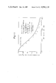
- FIG. 11 shows the experimental result of the apparatus of FIG. 9.
- E 1 (t) and E 2 (t) are the amplitudes of the desired signal and the undesired signal, respectively, and it is assumed that they are in Rayleigh distribution.
- the ⁇ 1 and ⁇ 2 are the angular velocity of the desired wave and the undesired wave, respectively, and ⁇ 1 and ⁇ 2 are the frequency shifts of the desired wave and the undesired wave by a modulation signal, respectively.
- P 1 and the P 2 are the frequencies of the modulation signals of the desired signal and the undesired signal, respectively.
- ⁇ is the phase difference between the desired wave and the undesired wave
- ⁇ is the phase difference between the desired modulation signal and the undesired modulation signal.
- the envelope output of the square-detector of e is expressed by the equation (6).
- FIG. 1 shows an example of the envelope output R(t), in which the curve (1) shows the envelope R(t), and the curve (2) shows the value E 1 2 (t)+E 2 2 (t) which is the low frequency spectrum component of the envelope output R(t). It nearly equals to the fading frequency which depends upon the velocity of a mobile, and the wavelength of electromagnetic wave. When a mobile moves at 40 Km/hour, and the carrier frequency is 900 MHz, said low frequency component is about 30 Hz.
- the 2E 1 (t)E 2 (t)cos( ⁇ (t)) in the equation (6) has the high frequency spectrum higher than Rayleigh fading frequency. That high frequency component is generated by the angular modulation, or the small difference of the carrier frequencies between the desired signal and the undesired signal.
- the average of the low frequency component ⁇ E 1 2 (t)+E 2 2 (t)> and the average of the high frequency spectrum component ⁇ E 1 (t)E 2 (t)> are measured by using an analog-digital converter, and then, the D/U is calculated by using said two average values.
- the analog-digital converter samples the input signal at the time (t) and the time (t+ ⁇ t) as shown in FIG. 1.
- the sampled values R(t) and R(t+ ⁇ t) at the time (t) and (t+ ⁇ t) are expressed by the equation (7).
- the sampling delay time ⁇ t is selected so that the equation (10) is satisfied for E 1 and E 2 which vary according to Rayleigh fading, and the equation (11) is satisfied for cos( ⁇ ), and cos( ⁇ .sub. ⁇ ) which varies quickly.
- the equation (11) means that cos( ⁇ ) has no correlation with cos( ⁇ .sub. ⁇ ). Then, the equation (9) is changed to the equation (12).
- the equation (14) is derived from the equations (8), (12) and (13).
- the value of the equation (15) is a real number, from which may be calculated the interference value ( ⁇ ).
- Equation (21) shows that Y is influenced by the product of ⁇ t and f m .
- FIG. 2 shows the curves of ⁇ Z 2 >/Y.
- the influence of f m ⁇ t depends upon the value ( ⁇ ), and the larger the value ( ⁇ ) is, the larger the influence is.
- the solid lines in FIG. 3 are theoretically calculated value, and the dots show the measured values. It should be noted that the ideal line in FIG. 3 is the 45° line which has no error.
- the value ( ⁇ M ) becomes theoretically and experimentally smaller than the value ( ⁇ t ) when f m ⁇ t is large, and the error is large when ( ⁇ t ) is large.
- the value f m ⁇ t must be less than 0.03 because the error becomes less than 1 dB when ( ⁇ t ) is smaller than 15 dB.
- ⁇ 1 1000 Hz
- ⁇ 2 1010 Hz
- the modulation signal is a sine wave signal
- P 1 200 Hz
- P 2 is in the range between 195 Hz and 205 Hz.
- 2 ⁇ cos( ⁇ )cos( ⁇ .sub. ⁇ )> is substantially zero when ⁇ t is larger than 0.4 msec, therefore, it is preferably that ⁇ t is larger than 0.4 msec.
- FIG. 5 shows the influence of ⁇ t to the value ( ⁇ M ) under the conditions of FIG. 4.
- the value ( ⁇ M ) becomes large, and thus the influence is large when ( ⁇ t ) is large.
- the reason why ( ⁇ M ) becomes large, is that Y becomes small when ⁇ t is small.
- FIG. 6 shows a block diagram of an embodiment of the present invention, in which the upper portion shows the experimental unit for testing the present apparatus, and the lower portion 90 enclosed by a dotted line is the present interference detector.
- reference numeral 3 is an oscillator for the generating a desired signal (D), which is angular-modulated by the modulation signal on the terminal 3a.
- Oscillator 6 generates undesired signal (U), which is also angular-modulated by the modulation signal on the terminal 6a.
- Fading simulators 4 and 7 provide artificial fading to both the desired signal (D) and the undesired signal (U), and 5 and 8 are variable attenuators.
- Combiner 9 combines both the desired signal (D) and the undesired signal (U), and 10 is a receiver which provides the intermediate frequency output (IF OUT).
- the IF OUT signal is applied to the present interference detector 90, which has an amplifier 11, an envelope detector 12, a pair of analog-digital converters 13 and 14, a processor 15 and a delay circuit 22.
- the amplifier 11 is a logarithmic amplifier, and the corresponding logarithmic expander 15a is inserted at the input portion of the processor 15 so that signal processed by the envelope detector 12 and converter 13 and/or 14 has a small dynamic range.
- FIG. 7A shows a flow-chart of the processor 15 when the processor 15 is implemented by a programmed computer
- FIG. 7B shows a block diagram of the processor 15 when the processor is implemented by hardware.
- the sampling number N is set in the counter 15b (FIG. 7B, box 100 in FIG. 7A).
- the number N is usually 500-1000 in case of Rayleigh fading.
- the delay time ⁇ t is also set and the value ⁇ t is applied to the delay circuit 22 which delays the sampling trigger signal by ⁇ t.
- the first A/D converter 13 provides the signal value R i (t) sampled at the time (t)
- the second converter 14 provides the signal value R i (t+ ⁇ t) sampled at the time (t+ ⁇ t).
- the calculator 15g in FIG. 7B or the box 116 in FIG. 7A calculates the value (k 2 -1) in order to assure that said value (k 2 -1) is positive. If that value (k 2 -1) is negative, the present system is reinitialized, and the above operation is carried out again.
- the calculator 15h in FIG. 7B or the box 120 in FIG. 7A calculates the value ##EQU9## which is the resultant interference.
- FIG. 8 shows another embodiment of the present invention, in which the calculation is accomplished by hardware without using a programmed means.
- the reference numeral 20 is an antenna
- 10 is a receiver
- 12 is an envelope detector
- 23 is a smoother circuit
- 24 is a squaring circuit
- 25 is a divider circuit
- 26 is a level meter
- 27 is a delay circuit
- 28 is a differential amplifier
- 29 is a square circuit
- 30 is a smoother circuit.
- both the desired signal (D) and the undesired signal (U) enter into the receiver 10 through the antenna 20.
- the intermediate frequency output (IF out ) is applied to the envelope detector 12.
- the output of the detector 12 is applied to the smoother 23, which, then, flattens the high frequency component of the envelope detected signal, therefore, that smoother 23 provides the low frequency component X expressed by the equation (8).
- the squaring circuit 24 provides the square X 2 , as follows. ##EQU10##
- the output of the detector 12 is also applied to the delay circuit 27, which delays the signal by the time ⁇ t.
- the delayed signal and the non-delayed signal are applied to the differential amplifier 28, the output of which is applied to the squaring circuit 29.
- the output of the squaring circuit 29 is smoothed by the smoother 30. Accordingly, the output of the smoother 30 is the high frequency component Y of the equation (12).
- FIG. 9 shows still another embodiment of the present invention, in which the reference numeral 20 is an antenna, 10 is a receiver, 43 is an AGC (Automatic Gain Control) circuit, 44 is an envelope detector, 45 is an amplifier, 46 is a high-pass filter, 47 is a detector, 48 is a low-pass filter, 49 is a smoother circuit, 50 is another smoother circuit, and 51 is a level meter.
- FIG. 10 shows the waveforms of the apparatus of FIG. 9, and 62 is the waveform of the output of the detector 44, 63 is the waveform of the high-pass filter 46, 64 is the waveform of the detector 47, and 65 is the waveform of the smoother circuit 50.
- both the desired signal D and the undesired signal U are applied to the receiver 10 through the antenna 20.
- the intermediate frequency output IF OUT of the receiver 10 is applied to the envelope detector 44 through the AGC amplifier 43.
- the time constant of the loop circuits of 43, 44 and 49 is very large so that that loop circuit removes only the variation of the median value level which is usually 0.1-1.0 Hz.
- the output of the envelope detector 44 is shown in the equation (6) and the waveform 62 in FIG. 10.
- the output of the detector 44 is applied to the high-pass filter 46 through the amplifier 45.
- the high-pass filter 46 removes the low frequency component (E 1 2 +E 2 2 ), and then the output of the high-pass filter 46 is the waveform 63 of FIG. 10.
- the waveform 63 is processed by the envelope detector 47 and the low-pass filter 48, then, the product of the desired signal E 1 and the undesired signal E 2 is obtained as shown in the following formula.
- the value Y" is an instantaneous value and varies by fading. Therefore, the waveform is processed as shown by the waveform 65 in FIG. 10 by the smoother 50, and the square root of the square average of Y" is indicated by the level meter 51.
- the indicated value W by the meter 51 is;
- FIG. 11 shows the experimental curve of the apparatus of FIG. 9.
- the horizontal axis shows the set value D/U ratio
- the vertical axis shows the measured value W
- the solid line shows the theoretical curve
- the dots show the measured value. The measured value coincides well with the theoretical solid curve.
- an envelope detection may be not only a square detection, but also a 4'th order detection, or any order detection.
- pilot signal outside of the signal band for the easy detection of the beat between the desired signal and the undesired signal.
- That pilot signal is preferably modulated in angular modulation.
- the carrier frequency of the first transmitter may be a little different from that of the second transmitter so that the beat frequency between the two carriers is easily detected.
- the present invention detects a cochannel interference very easily, and can be used for instance in a mobile communication, or cordless telephone.
Abstract
Description
e.sub.1 =E.sub.1 (t) sin(ω.sub.1 t+(Δω.sub.1)/(P.sub.1) sin P.sub.1 t) (1)
e.sub.2 =E.sub.2 (t) sin(ω.sub.2 t+φ+((Δω.sub.2)/(P.sub.2))sin(P.sub.2 t+θ)) (2)
R(t)=E.sub.1.sup.2 (t)+E.sub.2.sup.2 (t)+2E.sub.1 (t)E.sub.2 (t)cos(ψ(t)) (6)
R(t)=E.sub.1.sup.2 +E.sub.2.sup.2 +2E.sub.1 E.sub.2 cos(ψ) R(t+Δt)=E.sub.1.sup.2.sub.Δ +E.sub.2.sup.2.sub.Δ +2E.sub.2Δ E.sub.2Δ cos(ψ.sub.Δ) (7)
E.sub.1 ≈E.sub.1Δ, E.sub.2 ≈E.sub.2Δ(10)
<cos(ψ)cos(ψ.sub.Δ)>≈0 (11)
<[R(t)-R(t+Δt)].sup.2 >=4<E.sub.1.sup.2 ><E.sub.2.sup.2 >=Y (12)
(Γ)=(D/U)=<E.sub.1.sup.2 >/<E.sub.2.sup.2 > (13)
(Γ).sup.2 -2K(Γ)+1=0 (14)
K=(2X.sup.2 /Y)-1=(<E.sub.1.sup.2 >+<E.sub.2.sup.2 >)/(2<E.sub.1.sup.2 ><E.sub.2.sup.2 >) (16)
Y'=<Z.sup.2 >+4<E.sub.1.sup.2 ><E.sub.2.sup.2 > (19)
<Z.sup.2 >=8b.sub.2.sup.2 [Γ.sup.2 (1-ρ.sub.1.sup.2)+(1-ρ.sub.2.sup.2)] (20)
(ρ)=J.sub.0 (2πf.sub.m Δt) (21)
Y'=4<E.sub.2.sup.2 ><E.sub.2.sup.2 >(1-2<cos(ψ)cos(ψ.sub.66)>) (22)
Y"=2E.sub.1 E.sub.2
W=2(<E.sub.1.sup.2 ><E.sub.2.sup.2 >).sup.1/2 (26)
X=<E.sub.1.sup.2 >+<E.sub.2.sup.2 >=C (constant) (27)
Claims (6)
Applications Claiming Priority (4)
| Application Number | Priority Date | Filing Date | Title |
|---|---|---|---|
| JP58018102A JPS59144232A (en) | 1983-02-08 | 1983-02-08 | Detection system for identifical frequency interference amount |
| JP58-18102 | 1983-02-08 | ||
| JP58-68428 | 1983-04-20 | ||
| JP58068428A JPS59194542A (en) | 1983-04-20 | 1983-04-20 | Method for detecting interference quantity of same frequency |
Publications (1)
| Publication Number | Publication Date |
|---|---|
| US4561114A true US4561114A (en) | 1985-12-24 |
Family
ID=26354724
Family Applications (1)
| Application Number | Title | Priority Date | Filing Date |
|---|---|---|---|
| US06/541,842 Expired - Lifetime US4561114A (en) | 1983-02-08 | 1983-10-14 | Cochannel interference measurement system |
Country Status (3)
| Country | Link |
|---|---|
| US (1) | US4561114A (en) |
| EP (1) | EP0117946B1 (en) |
| DE (1) | DE3379252D1 (en) |
Cited By (10)
| Publication number | Priority date | Publication date | Assignee | Title |
|---|---|---|---|---|
| US4861385A (en) * | 1986-10-02 | 1989-08-29 | Aisaburo Yagishita | Article washing method |
| US4998289A (en) * | 1988-06-02 | 1991-03-05 | Motorola, Inc. | Signal integrity control technique for an RF communication system |
| WO1992020165A1 (en) * | 1991-04-29 | 1992-11-12 | Motorola, Inc. | Interference detection technique |
| US5203008A (en) * | 1989-11-28 | 1993-04-13 | Nippon Telegraph & Telephone Corporation | Method of assigning radio communication channels to each of a plurality of mobile stations |
| EP0673129A2 (en) * | 1994-03-18 | 1995-09-20 | DeTeMobil Deutsche Telekom MobilNet GmbH | Method and apparatus for determining the C/I ratio for co-channel or adjacent channel interferene in digital mobile radio networks |
| US5533055A (en) * | 1993-01-22 | 1996-07-02 | Motorola, Inc. | Carrier to interference ratio measurement |
| US6567646B1 (en) | 1998-12-23 | 2003-05-20 | Telefonaktiebolaget Lm Ericsson (Publ) | Method and apparatus in a radio communication system |
| US20050239406A1 (en) * | 1997-05-23 | 2005-10-27 | Shattil Steve J | Cancellation system for frequency reuse in microwave communications |
| US20060229751A1 (en) * | 2005-04-04 | 2006-10-12 | Barnhill Matthew S | Signal quality estimation and control system |
| US20060269021A1 (en) * | 2005-05-26 | 2006-11-30 | Brima Ibrahim | Method and system for FM interference detection and mitigation |
Families Citing this family (2)
| Publication number | Priority date | Publication date | Assignee | Title |
|---|---|---|---|---|
| IL89961A (en) * | 1988-06-02 | 1992-12-01 | Motorola Inc | Interference detecting circuit for high frequency angular modulated system |
| DE3925629A1 (en) * | 1989-08-03 | 1991-02-07 | Grundig Emv | METHOD FOR DETECTING MULTIPLE-WAY DISTORTIONS IN FM BROADCAST RECEIVING AND CIRCUIT ARRANGEMENT FOR IMPLEMENTING THE METHOD |
Citations (2)
| Publication number | Priority date | Publication date | Assignee | Title |
|---|---|---|---|---|
| US4085370A (en) * | 1975-02-10 | 1978-04-18 | U.S. Philips Corporation | Radio receiver having co-channel interference operated squelch |
| US4124818A (en) * | 1977-10-04 | 1978-11-07 | Bell Telephone Laboratories, Incorporated | Arrangement for monitoring signal-to-interference ratio in a radio transmission system |
Family Cites Families (4)
| Publication number | Priority date | Publication date | Assignee | Title |
|---|---|---|---|---|
| US3925732A (en) * | 1974-01-14 | 1975-12-09 | Furuno Electric Co | Signal detecting device |
| US4038604A (en) * | 1975-12-15 | 1977-07-26 | Cincinnati Electronics Corporation | Signal to noise ratio indicating circuit |
| JPS5428669A (en) * | 1977-08-08 | 1979-03-03 | Nec Corp | Noise measuring circuit |
| US4317214A (en) * | 1980-07-14 | 1982-02-23 | Attinello John S | Apparatus for simulating interference transmissions |
-
1983
- 1983-10-14 US US06/541,842 patent/US4561114A/en not_active Expired - Lifetime
- 1983-11-24 EP EP83307195A patent/EP0117946B1/en not_active Expired
- 1983-11-24 DE DE8383307195T patent/DE3379252D1/en not_active Expired
Patent Citations (2)
| Publication number | Priority date | Publication date | Assignee | Title |
|---|---|---|---|---|
| US4085370A (en) * | 1975-02-10 | 1978-04-18 | U.S. Philips Corporation | Radio receiver having co-channel interference operated squelch |
| US4124818A (en) * | 1977-10-04 | 1978-11-07 | Bell Telephone Laboratories, Incorporated | Arrangement for monitoring signal-to-interference ratio in a radio transmission system |
Cited By (19)
| Publication number | Priority date | Publication date | Assignee | Title |
|---|---|---|---|---|
| US4861385A (en) * | 1986-10-02 | 1989-08-29 | Aisaburo Yagishita | Article washing method |
| US4998289A (en) * | 1988-06-02 | 1991-03-05 | Motorola, Inc. | Signal integrity control technique for an RF communication system |
| US5203008A (en) * | 1989-11-28 | 1993-04-13 | Nippon Telegraph & Telephone Corporation | Method of assigning radio communication channels to each of a plurality of mobile stations |
| US5603087A (en) * | 1991-04-29 | 1997-02-11 | Motorola, Inc. | Interference detection technique |
| GB2262017B (en) * | 1991-04-29 | 1995-06-14 | Motorola Inc | Interference detection technique |
| WO1992020165A1 (en) * | 1991-04-29 | 1992-11-12 | Motorola, Inc. | Interference detection technique |
| GB2262017A (en) * | 1991-04-29 | 1993-06-02 | Motorola Inc | Interference detection technique |
| US5533055A (en) * | 1993-01-22 | 1996-07-02 | Motorola, Inc. | Carrier to interference ratio measurement |
| EP0673129A2 (en) * | 1994-03-18 | 1995-09-20 | DeTeMobil Deutsche Telekom MobilNet GmbH | Method and apparatus for determining the C/I ratio for co-channel or adjacent channel interferene in digital mobile radio networks |
| EP0673129A3 (en) * | 1994-03-18 | 1999-09-08 | DeTeMobil Deutsche Telekom MobilNet GmbH | Method and apparatus for determining the C/I ratio for co-channel or adjacent channel interferene in digital mobile radio networks |
| US7283799B2 (en) * | 1997-05-23 | 2007-10-16 | Lot 41 Acquisition Foundation, Llc | Cancellation system for frequency reuse in microwave communications |
| US20050239406A1 (en) * | 1997-05-23 | 2005-10-27 | Shattil Steve J | Cancellation system for frequency reuse in microwave communications |
| US7477921B2 (en) | 1997-05-23 | 2009-01-13 | Lot 42 Acquisition Foundation, Llc | Cancellation system for frequency reuse in microwave communications |
| US20080039147A1 (en) * | 1997-05-23 | 2008-02-14 | Shattil Steve J | Cancellation System for Frequency Reuse in Microwave Communications |
| US6567646B1 (en) | 1998-12-23 | 2003-05-20 | Telefonaktiebolaget Lm Ericsson (Publ) | Method and apparatus in a radio communication system |
| US20060229751A1 (en) * | 2005-04-04 | 2006-10-12 | Barnhill Matthew S | Signal quality estimation and control system |
| US8014741B2 (en) * | 2005-04-04 | 2011-09-06 | That Corporation | Signal quality estimation and control system |
| US20060269021A1 (en) * | 2005-05-26 | 2006-11-30 | Brima Ibrahim | Method and system for FM interference detection and mitigation |
| US8811468B2 (en) * | 2005-05-26 | 2014-08-19 | Broadcom Corporation | Method and system for FM interference detection and mitigation |
Also Published As
| Publication number | Publication date |
|---|---|
| EP0117946B1 (en) | 1989-02-22 |
| EP0117946A3 (en) | 1986-01-15 |
| DE3379252D1 (en) | 1989-03-30 |
| EP0117946A2 (en) | 1984-09-12 |
Similar Documents
| Publication | Publication Date | Title |
|---|---|---|
| US4561114A (en) | Cochannel interference measurement system | |
| US5677695A (en) | Radar apparatus for detecting a distance/velocity | |
| US4315260A (en) | Method and apparatus for measuring the distance between a primary station and a secondary station | |
| US4323899A (en) | Polarization detector | |
| US5303262A (en) | Method and apparatus for triggering measurements from a TDMA signal | |
| CA2231147C (en) | Apparatus for distance measurement | |
| US4599618A (en) | Nearest return tracking in an FMCW system | |
| KR960009925B1 (en) | Rapid received signal strength indication | |
| US5603087A (en) | Interference detection technique | |
| US4211979A (en) | Circuit arrangement for eliminating waveform distortion of an angle-modulated signal transmitted over multipaths | |
| EP0664009A1 (en) | Burst tone range processing system and method | |
| US6977611B1 (en) | FM-CW altimeter detector | |
| JPH0626331B2 (en) | Signal processing method | |
| US4208659A (en) | System for use in an aircraft for obstacle detection | |
| EP0048170B1 (en) | Radar ranging system | |
| US4888787A (en) | Receiver apparatus for spread spectrum communication systems | |
| US5455845A (en) | Microwave receiver having coherent threshold detection | |
| US6567646B1 (en) | Method and apparatus in a radio communication system | |
| EP0042730A1 (en) | Radar polarisation detector and method of radar target detection | |
| US4608568A (en) | Speed detecting device employing a Doppler radar | |
| US4109250A (en) | Circuit for the comparative vector measurement of radio signal pulses which arrive approximately simultaneously in a plurality of receivers | |
| Sue | Block 4 receiver tracking loop performance in the presence of a CW RFI | |
| US3324401A (en) | Direct indicating frequency determining circuit employing peak detecting combined delayed and undelayed signals of unknown frequency | |
| US3090044A (en) | Radio direction finding systems | |
| JPH0119779B2 (en) |
Legal Events
| Date | Code | Title | Description |
|---|---|---|---|
| AS | Assignment |
Owner name: NIPPON ELGRAPH & TELEPHONE PUBLIC CORPORATION 1-6 Free format text: ASSIGNMENT OF ASSIGNORS INTEREST.;ASSIGNORS:KOZONO, SHIGERU;ISHIKAWA, KEIICHI;REEL/FRAME:004185/0392 Effective date: 19830926 |
|
| AS | Assignment |
Owner name: NIPPON TELEGRAPH & TELEPHONE CORPORATION Free format text: CHANGE OF NAME;ASSIGNOR:NIPPON TELEGRAPH AND TELEPHONE PUBLIC CORPORATION;REEL/FRAME:004454/0001 Effective date: 19850718 |
|
| STCF | Information on status: patent grant |
Free format text: PATENTED CASE |
|
| FEPP | Fee payment procedure |
Free format text: PAYOR NUMBER ASSIGNED (ORIGINAL EVENT CODE: ASPN); ENTITY STATUS OF PATENT OWNER: LARGE ENTITY |
|
| FPAY | Fee payment |
Year of fee payment: 4 |
|
| FPAY | Fee payment |
Year of fee payment: 8 |
|
| AS | Assignment |
Owner name: NTT MOBILE COMMUNICATIONS NETWORK INC., JAPAN Free format text: ASSIGNOR ASSIGNS AN UNDIVIDED FIFTY PERCENT (50%) INTEREST TO THE ASSIGNEE.;ASSIGNOR:NIPPON TELEGRAPH AND TELEPHONE CORPORATION;REEL/FRAME:006806/0881 Effective date: 19931130 |
|
| AS | Assignment |
Owner name: NIPPON TELEGRAPH AND TELEPHONE CORPORATION, JAPAN Free format text: CHANGE OF ADDRESS;ASSIGNOR:NIPPON TELEGRAPH AND TELEPHONE CORPORATION;REEL/FRAME:008048/0086 Effective date: 19950918 |
|
| FPAY | Fee payment |
Year of fee payment: 12 |