US4542344A - Detecting buried pipeline depth and location with electromagnetic triangulation - Google Patents
Detecting buried pipeline depth and location with electromagnetic triangulation Download PDFInfo
- Publication number
- US4542344A US4542344A US06/528,892 US52889283A US4542344A US 4542344 A US4542344 A US 4542344A US 52889283 A US52889283 A US 52889283A US 4542344 A US4542344 A US 4542344A
- Authority
- US
- United States
- Prior art keywords
- pipeline
- detectors
- signals
- depth
- sets
- Prior art date
- Legal status (The legal status is an assumption and is not a legal conclusion. Google has not performed a legal analysis and makes no representation as to the accuracy of the status listed.)
- Expired - Fee Related
Links
Images


Classifications
-
- G—PHYSICS
- G01—MEASURING; TESTING
- G01V—GEOPHYSICS; GRAVITATIONAL MEASUREMENTS; DETECTING MASSES OR OBJECTS; TAGS
- G01V3/00—Electric or magnetic prospecting or detecting; Measuring magnetic field characteristics of the earth, e.g. declination, deviation
- G01V3/02—Electric or magnetic prospecting or detecting; Measuring magnetic field characteristics of the earth, e.g. declination, deviation operating with propagation of electric current
- G01V3/06—Electric or magnetic prospecting or detecting; Measuring magnetic field characteristics of the earth, e.g. declination, deviation operating with propagation of electric current using ac
-
- G—PHYSICS
- G01—MEASURING; TESTING
- G01V—GEOPHYSICS; GRAVITATIONAL MEASUREMENTS; DETECTING MASSES OR OBJECTS; TAGS
- G01V3/00—Electric or magnetic prospecting or detecting; Measuring magnetic field characteristics of the earth, e.g. declination, deviation
- G01V3/15—Electric or magnetic prospecting or detecting; Measuring magnetic field characteristics of the earth, e.g. declination, deviation specially adapted for use during transport, e.g. by a person, vehicle or boat
Definitions
- This invention relates to means for finding underground conductors and more particularly it relates to pipeline finders capable of surveying underground pipeline location and depth.
- signal amplitude variation may be used in a simple accurate system for direct readout of both depth and orientation distances.
- This may be achieved by employing a mount bar of fixed length between two reception locations supported a known distance from the surface in a triangulation computation method characterized by two orthogonally disposed antennas in corresponding sets at each reception location, to receive electromagnetic signals radiated from the pipeline at some desired frequency, preferably 640 Hz.
- Each antenna in each set preferably comprises a ferrite rod with a solenoid coil wound thereon, thereby providing four detected signals, which are multiplexed into a single amplification channel with automatic gain control for maintaining output signals within a preferred range of amplitudes for digitizing the respective signal amplitudes.
- the desired depth and offset location of the pipeline are calculated therefrom in an electronic calculator for digital readout.
- the instrument may be used continuously to survey a pipeline providing the two sets of antennas are located on opposite sides thereof.
- the signals may be automatically recorded upon a medium advanced by distance measuring instrumentation.
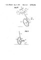
- FIG. 1 is a diagrammatic sketch looking into a pipeline of the system in operation on the surface at the location of an underground pipeline;
- FIG. 2 is a general block diagram of the system for calculating from four particular detected signals the depth and offset distances of the pipeline from the location of the instrumentation;
- FIG. 3 is a system block diagram of the preferred embodiment of the invention.
- FIGS. 4-5 show instrumentation for advancing a recorder medium to relate readings with particular locations along the pipeline.
- FIG. 1 it is seen that two sets A,B and C,D of orthogonally oriented antennas A, B, C and D are separated a space of several feet by a rod 15. They are also supported by post 16 a known distance from the ground surface 17 in which pipeline 18 is buried. If the unit is carried on the back of a person, it is supported the known distance from the ground in this alternative manner. To wit, a portable receiver-indicator unit 19 is manually moved along the pipeline 18 with only one operating criterion, namely that the orthogonal antenna sets A,B and C,D straddle the pipeline 18.
- Transmitter 20 radiates electromagnetic energy at 640 Hz underground with enough power to induce electromagnetic energy along underground pipeline 18 for producing detectable radiation at the site of the receiver unit 19 and antenna sets A,B and C,D.
- a conductive connection pair to earth and the pipeline 18 may be used from transmitter 20.
- Each antenna unit preferable comprises a ferrite rod 21 with a solenoid winding 22 thereon.
- One such rod 21 of each set (B,C) is vertically disposed and the other (A,D) is horizontally disposed.
- a marker such as flag 23 may be introduced in the ground surface as a survey marker post directly over the pipeline location and the flag may carry a notation of the distance below the surface to the pipeline.
- the portable receiver-indicator unit 19 preferably processes the signals from the four antennas A, B, C, D to provide both depth and offset distance readings in visible form for reading of the surveyor in situ without calculation. These may be recorded if desired or stored in the computer 24 which controls the multiplexing-gating-demultiplexing operation by way of lead 25.
- the four detected signals A, B, C, D of various amplitudes depending upon pipeline location and depth are multiplexed by multiplexer 26 into a single channel 27 feeding AGC amplifier 28.
- the AGC amplifier 28 serves the important purpose of making certain that a set of variable amplitude signals A, B, C, D is available all within a range of amplitude (1 to 3 volts) which is compatible with processing circuits such as demultiplexer 29 and the calculating circuits in computer 24. Then the computer 24 is programmed to work out the triangulation results and to provide readout entries for the depth at 30 and offset distance at 31.
- the AGC amplifier 28 is of the gated type and thus the AGC is turned off during the sampling period to permit the individual signals A, B, C or D to find their own level and be a true representation of their instantaneous amplitude unaltered by the AGC action.
- Other means may be used to achieve this function as will be described hereinafter.
- the control computer 24 provides a periodic sampling in sequence of the signals A, B, C and D in a repetitive cyclic pattern. For 640 Hz square wave radiated electromagnetic signals, 25 m.s. samples are taken 40 times per second under control of computer 24.
- the preferred computer embodiment of FIG. 3 generally follows the general format described and uses like reference characters where applicable with primes indicating general functional similarity but different details. It is noted that in this case the computer 24' is a digital microprocessor, such as available from the Synapse Corp., Model CP06805. This is primarily a Motorola 1.4-6805E2 digital computer having a National ADC0831 analog to digital conversion unit 35.
- the microprocessor 24' has register means 36 for storing digital output readings on the depth 30 and offset 31 indicators, or for alternatively or simultaneously recording into a memory bank or on a strip recorder, if desired also for the offset signals 31 an audible tone is derived at 37, to enable an operator to keep the survey unit antenna sets A,B and C,D astraddle the pipeline during the course of a survey.
- This signal is not critical but it greatly enhances the speed and agility with which the instrument may be used to trace the course of a pipeline on a survey mission.
- Each channel has an adjustable gain tuned (at 640 Hz) amplifier channel 38A, 38B, etc. These have gain set only for calibrating the instrument, and typically provide a 50 DB signal gain. Thereafter the output level gain at lead 44 is held within a preferred range (0-5v) for digital processing at the digital converter 35 by means of AGC amplifier 28, which is compensated to permit individual signal sampling of instantaneous voltage levels while maintaining the system gain at an optimum level.
- AGC amplifier 28 is compensated to permit individual signal sampling of instantaneous voltage levels while maintaining the system gain at an optimum level.
- the amplifier 39 has a feedback loop comprising detector 41, a first low pass (100 Hz) filter 42 and a second low pass (0.2 Hz) filter 43. This provides an output signal at lead 44 for the A-D converter 35 and a feedback gain control signal at lead 45.
- this system functions to establish the desired overall gain control while passing the appropriate instantaneous levels (1 to 3v) of the signal samples to the A-D converter 35 along lead 44.
- These samples are processed by programming the microprocessor 24' to average each signal amplitude against the prior four amplitude samples to serve as a digital filter, and the averaged signal amplitude for each channel A, B, C and D is used in the triangulation calculations programmed in the microprocessor 24' to derive the depth (30) and offset (31) distances.
- the signals from the coils are connected to adjustable-gain amplifiers 38 tuned to the transmitter unit frequency of 640 hertz.
- the gains of these amplifiers are preset to compensate for minor variations in antenna A, B, C, D sensitivities.
- the outputs of the amplifiers are connected to analog signal multiplexer 26 which provides an output signal which is a time multiplexed sequence of the four inputs A, B, C, D. This multiplexing is controlled synchronously by the microprocessor 24' switching and timing circuitry.
- AGC automatic gain control
- This AGC amplifier is designed so that relative signal level variations between sensors A, B, C, D are not equalized, but overall variations due to equivalent decreases in all four antenna sensors are compensated for. Therefore, the output of the AGC amplifier has a constant average amplitude, but relative amplitudes between the four sensor signals are preserved.
- the AGC amplifier is comprised of a gain controlled amplifier 39, detector 41, low-pass filter 42 and loop filter 43 of lower frequency, all connected in a gain control feedback loop.
- the output of the first low-pass filter is a signal of constant average amplitude with variations in instantaneous DC amplitude level corresponding to the sampled sensor signals.
- the output amplitude of the AGC amplifier is connected to analog-to-digital (A/D) converter 35 which converts the instantaneous DC levels to digital outputs corresponding to the input signals.
- A/D analog-to-digital
- the microprocessor 24' controls the conversion timing and inputs the digitized data and retains them for calculations.
- the microprocessor 24' accepts the digitized data, computes the depth 30 and offset 31 distances using the equations derived hereinafter. It provides digital readouts of the depth and offset, and controls the synchronous timing of the analog signal multiplexer 26, A/D converter 35 (demultiplexer) and the digital output register 36.
- the digital output register 36 multiplexes the output of the microprocessor 24' to the proper digital-to-analog (D/A) converter.
- the outputs of the D/A converters are DC voltages proportional to the depth and offset. These voltages are suitable for recording on a strip chart recorder.
- an audible offset indicator 37 connected to the offset indication output is used to aid the instrument operator in maintaining the sensor assembly sets A,B and C,D on opposite sides of the buried pipeline 18 structure.
- FIG. 3 The preferred implementation of the invention in FIG. 3 is referenced for illustrative purposes. Other methods and variations of implementing this invention are possible, including the use of alternate magnetic field sensors containing semiconductor devices or coils without ferrite material, the use of alternate signal processing and calculation means such as an analog implementation of the multiplication and division operations or the use of digital multiplication and division units, the use of other displays of the calculated parameters, such as recorders on magnetic or semiconductor media.
- the sensor configuration shown in FIG. 1 has an orthogonal pair of sensors A and B spaced a distance R from another pair of orthogonal sensors C and D.
- the conductor being located is any location l offset from sensor pair A,B and depth d beneath the sensors as shown in the figure.
- ⁇ o is the free-space permeability.
- the sensor voltages are ##EQU2## where k is a sensor sensitivity factor. Taking the ratios of these voltages yields ##EQU3## Solving these two equations for d and l yields: Alternately, if the offset of the pipe is measured from the center of the sensor array, then: ##EQU4##
- both the detector hereinbefore described with detector coils 21 and a built-in recorder with a paper or magnetic tape medium as desired designated as unit 49 may be mounted on shaft 50 for manual advancing with handle 51 on wheel 52.
- an optical code disc 53, or the like is rotated by wheel 52 of known calibrated circumference in contact with the earth as the conveyance is pushed along the pipeline course.
- pulses are produced for advancing the recorder medium proportionally to the distance travelled.
- FIG. 5 The embodiment of FIG. 5 is similar in purpose, but employs a slack chain principal of measurement. That is the slack plastic cord 60, or the like, laid out along the course of the pipeline is wrapped around drum 61 of known calibrated circumference to turn the encoding disc assembly 53 and measure the course distance as the instrument is moved along the pipeline. In both cases a predetermined number of electrical pulses per wheel revolution may be generated for appropriate recording medium advancement rates.
- This slack chain principle is particularly appropriate if the unit is carried on the back of a person and the chain is manually manipulated.
- the instrumentation is well adapted for one person surveys to move a manual transport conveyance such as shown along the pipeline course to record the depth and offset data.
- a temporary marker such as chalk line can be deposited from the transport conveyance to utilize the offset data on the recorded medium.
- the slack line 60 may be left in place for the same purpose. Therefore the instrumentation may produce recorded data located as a function of the movement of the conveyance for identifying signals at specific pipeline locations from a single person surveyor.
- the operating procedure for surveying the position of a buried pipeline is as follows:
- the output of the transmitter unit 20 (FIG. 1) is connected to a cathodic protection test point and a distant grounded metal electrode (or alternately radiating in the vicinity of the pipeline 18) at a position where the pipeline 18 radiates the signals receivable by the antenna sets A,B - C,D straddling the pipeline 18.
- the sensor assembly is then positioned over the pipe and oriented perpendicular to the pipe axis by use of the audible signal 37 (FIG. 3).
- the operator positions the sensor assembly to obtain a minimum tone indication from the receiver unit audible tone output.
- a chart recorder is attached to the depth and location outputs from the receiver unit.
- a continuous recording of pipe depth and location is obtained. If only depth information is required, the operator need not maintain the minimum tone indication as long as the sensor array is kept within a reasonable lateral orientation re1ative to the pipe.
Abstract
Description
Claims (4)
Priority Applications (1)
| Application Number | Priority Date | Filing Date | Title |
|---|---|---|---|
| US06/528,892 US4542344A (en) | 1983-09-02 | 1983-09-02 | Detecting buried pipeline depth and location with electromagnetic triangulation |
Applications Claiming Priority (1)
| Application Number | Priority Date | Filing Date | Title |
|---|---|---|---|
| US06/528,892 US4542344A (en) | 1983-09-02 | 1983-09-02 | Detecting buried pipeline depth and location with electromagnetic triangulation |
Publications (1)
| Publication Number | Publication Date |
|---|---|
| US4542344A true US4542344A (en) | 1985-09-17 |
Family
ID=24107635
Family Applications (1)
| Application Number | Title | Priority Date | Filing Date |
|---|---|---|---|
| US06/528,892 Expired - Fee Related US4542344A (en) | 1983-09-02 | 1983-09-02 | Detecting buried pipeline depth and location with electromagnetic triangulation |
Country Status (1)
| Country | Link |
|---|---|
| US (1) | US4542344A (en) |
Cited By (56)
| Publication number | Priority date | Publication date | Assignee | Title |
|---|---|---|---|---|
| US4642786A (en) * | 1984-05-25 | 1987-02-10 | Position Orientation Systems, Ltd. | Method and apparatus for position and orientation measurement using a magnetic field and retransmission |
| DE3737146A1 (en) * | 1986-11-06 | 1988-05-11 | Ansaldo Spa | DEVICE FOR LOCATING ROUND IRON IN HIGH-STRENGTH STEEL CONCRETE |
| EP0388041A2 (en) * | 1989-03-17 | 1990-09-19 | Minnesota Mining And Manufacturing Company | Apparatus for determining direction to and position of an underground conductor |
| US4994747A (en) * | 1988-01-14 | 1991-02-19 | Stolar, Inc. | Method and apparatus for detecting underground electrically conductive objects |
| US5065098A (en) * | 1990-06-18 | 1991-11-12 | The Charles Machine Works, Inc. | System for locating concealed underground objects using digital filtering |
| US5066917A (en) * | 1990-01-17 | 1991-11-19 | Stolar, Inc. | Long feature vertical or horizontal electrical conductor detection methodology using phase coherent electromagnetic instrumentation |
| WO1991020002A1 (en) * | 1990-06-18 | 1991-12-26 | The Charles Machine Works, Inc. | An improved system for locating concealed underground objects |
| US5084710A (en) * | 1989-07-28 | 1992-01-28 | Minnesota Mining And Manufacturing Company | Electronic means for switching antennas to a common bus |
| US5151649A (en) * | 1990-01-23 | 1992-09-29 | Paul Heroux | Pair of electrically shielded triaxial magnetic sensors for determination of electric currents in conductors in air with distance and angle compensation |
| US5185578A (en) * | 1990-01-17 | 1993-02-09 | Stolar, Inc. | Method for detecting anomalous geological zones by transmitting electromagnetic energy between spaced drillholes using different frequency ranges |
| US5231355A (en) * | 1990-06-18 | 1993-07-27 | The Charles Machine Works, Inc. | Locator transmitter having an automatically tuned antenna |
| US5260660A (en) * | 1990-01-17 | 1993-11-09 | Stolar, Inc. | Method for calibrating a downhole receiver used in electromagnetic instrumentation for detecting an underground conductor |
| US5365163A (en) * | 1992-09-29 | 1994-11-15 | Minnesota Mining And Manufacturing Company | Sensor array for circuit tracer |
| US5430379A (en) * | 1993-08-27 | 1995-07-04 | Minnesota Mining And Manufacturing Company | Conductor locator adapter for electronic markers |
| WO1995030913A1 (en) * | 1994-05-06 | 1995-11-16 | Radiodetection Limited | Locator |
| US5471143A (en) * | 1993-01-29 | 1995-11-28 | Minnesota Mining And Manufacturing Co. | Apparatus for locating buried conductors using phase-shifted signals |
| US5479729A (en) * | 1994-04-04 | 1996-01-02 | At&T Corp. | Method and apparatus for controlling excavation eqiupment |
| DE19502935A1 (en) * | 1995-01-31 | 1996-08-01 | Ego Elektro Blanc & Fischer | Method and device for transmitting data from a cooking vessel to a cooking device |
| DE19646102C1 (en) * | 1996-11-08 | 1998-05-20 | Fraunhofer Ges Forschung | Device for contactless detection of objects |
| US5790476A (en) * | 1995-09-12 | 1998-08-04 | Motorola Inc. | Methods and systems for locating an underground sewer using a buoy |
| WO1998040764A1 (en) * | 1997-03-07 | 1998-09-17 | Radiodetection Limited | Locator of electrically conductive objects |
| FR2781059A1 (en) * | 1998-07-10 | 2000-01-14 | Electricite De France | Mapping a buried electrical earthing network for dispersion of lightning or electrical fault currents, injects voltage signals measures simultaneously the induced electric and magnetic fields in two different planes |
| US6130539A (en) * | 1998-08-19 | 2000-10-10 | Metrotech Corporation | Automatic gain control for a line locator |
| EP1058124A2 (en) * | 1999-06-05 | 2000-12-06 | Hagenuk KMT Kabelmesstechnik GmbH | Method and apparatus to determine the direction of arrival of electromagnetic waves |
| DE19933911A1 (en) * | 1999-07-20 | 2001-02-08 | Braas Flachdachsysteme Gmbh & | Measuring device for the detection of hidden ferromagnetic structures, in particular trapezoidal sheets in the lower layers of a roof structure |
| US6211807B1 (en) | 1999-05-26 | 2001-04-03 | Geometrics | System using spread spectrum modulation for locating underground objects |
| US6407550B1 (en) | 1998-08-19 | 2002-06-18 | Metrotech Corporation | Line locator with accurate horizontal displacement detection |
| US6411094B1 (en) | 1997-12-30 | 2002-06-25 | The Charles Machine Works, Inc. | System and method for determining orientation to an underground object |
| US6529006B1 (en) | 2001-10-31 | 2003-03-04 | Paul Hayes | Method and apparatus for resolving the position and identity of buried conductive bodies |
| US6617855B2 (en) * | 2000-03-24 | 2003-09-09 | Radiodetection Limited | Pipeline mapping and interrupter therefor |
| US6717410B2 (en) * | 2000-09-08 | 2004-04-06 | Merlin Technology, Inc. | Bore location system |
| US20040070399A1 (en) * | 2002-10-09 | 2004-04-15 | Olsson Mark S. | Omnidirectional sonde and line locator |
| US20040070535A1 (en) * | 2002-10-09 | 2004-04-15 | Olsson Mark S. | Single and multi-trace omnidirectional sonde and line locators and transmitter used therewith |
| US6776246B1 (en) | 2002-12-11 | 2004-08-17 | The Charles Machine Works, Inc. | Apparatus and method for simultaneously locating a fixed object and tracking a beacon |
| DE19917926B4 (en) * | 1998-04-23 | 2004-10-07 | Delphi Automotive Systems Deutschland Gmbh | antenna array |
| US20050062475A1 (en) * | 2003-09-22 | 2005-03-24 | Shinsuke Nakanishi | Cable location continuously determining apparatus, cable location continuously determining method, and cable location continuously determining program |
| US20050156601A1 (en) * | 2003-11-25 | 2005-07-21 | Dupuis Jerome C. | Induction magnetometer |
| US7201236B1 (en) | 2002-12-11 | 2007-04-10 | The Charles Machine Works, Inc. | Apparatus and method for tracking multiple signal emitting objects |
| US20080228072A1 (en) * | 2007-03-16 | 2008-09-18 | Warsaw Orthopedic, Inc. | Foreign Body Identifier |
| GB2453199A (en) * | 2007-09-28 | 2009-04-01 | Charles Machine Works | Magnetic field locator with two tri-axial antennas |
| US20100002938A1 (en) * | 2005-02-16 | 2010-01-07 | Mulcahey Butch Aka Donald M | Method of displaying digital image for digital locating system and device for underground object detection |
| US20100001714A1 (en) * | 2008-03-03 | 2010-01-07 | Radiodetection Limited | Detector for Calculating the Depth of a Buried Conductor |
| US20100253513A1 (en) * | 2008-10-02 | 2010-10-07 | Certusview Technologies, Llc | Locate transmitter having enhanced features for underground facility locate operations, and associated methods and systems |
| US20100289496A1 (en) * | 2005-05-13 | 2010-11-18 | The Charles Machine Works, Inc. | Dipole Locator Using Multiple Measurement Points |
| US8298382B2 (en) | 2010-12-15 | 2012-10-30 | Abriox Limited | Apparatus for use with metallic structures |
| US9329297B2 (en) | 2005-05-13 | 2016-05-03 | The Charles Machine Works, Inc. | Dipole locator using multiple measurement points |
| US9547101B2 (en) | 2007-09-28 | 2017-01-17 | The Charles Machine Works, Inc. | System for tracking a downhole tool assembly using dual above-ground receiver assemblies |
| WO2017164765A1 (en) * | 2016-03-22 | 2017-09-28 | Общество С Ограниченной Ответственностью " Техноас-Ск" | Determining depth of and distance to communications lines |
| WO2018046947A1 (en) * | 2016-09-09 | 2018-03-15 | Speir Hunter Ltd | Pipeline mapping system |
| DE102017210672A1 (en) * | 2017-06-23 | 2018-12-27 | Heinrich Hirdes Gmbh | Method for measuring a coverage of a line and device |
| WO2019245487A1 (en) | 2018-06-21 | 2019-12-26 | Nokta Muhendislik Ins. Elekt. Plas. Gida Ve Reklam San. Tic. Ltd. Sti. | Operating method of a metal detector capable of measuring target depth |
| CN111221046A (en) * | 2020-01-21 | 2020-06-02 | 清华大学 | Three-dimensional tracking method and device for in-pipeline detector |
| CN113418444A (en) * | 2021-07-05 | 2021-09-21 | 新余学院 | Method and device for deeply detecting non-excavation deeply-buried underground pipeline |
| US11204437B2 (en) | 2018-11-05 | 2021-12-21 | The Charles Machine Works, Inc. | Dipole locator using balanced antenna signals |
| US11397266B2 (en) | 2018-08-29 | 2022-07-26 | Subsite, Llc | GPS assisted walkover locating system and method |
| US11711104B2 (en) | 2019-10-21 | 2023-07-25 | The Charles Machine Works, Inc. | Noise minimization to communicate with a beacon |
Citations (14)
| Publication number | Priority date | Publication date | Assignee | Title |
|---|---|---|---|---|
| US2105247A (en) * | 1936-11-25 | 1938-01-11 | Jakosky John Jay | Method and apparatus for electrical exploration of the subsurface |
| US2974276A (en) * | 1957-08-16 | 1961-03-07 | Superior Oil Co | Method of and apparatus for use in measuring earth potentials |
| US3617865A (en) * | 1968-05-25 | 1971-11-02 | Goroku Hakata | Method and apparatus for locating a buried metallic line employing magnetic field gradient measurements |
| SU526838A1 (en) * | 1974-07-03 | 1976-08-30 | Физико-Механический Институт Ан Украинской Сср | The method of determining the location of the cable |
| US4021725A (en) * | 1976-03-05 | 1977-05-03 | The United States Of America As Represented By The Secretary Of The Navy | Mobile mine detection system having plural color display |
| US4112349A (en) * | 1977-05-09 | 1978-09-05 | Harold James Weber | Apparatus including bivolumetric tone subaudition means for positionally spotting and tracing subjacently concealed conductive structures |
| US4134061A (en) * | 1977-02-02 | 1979-01-09 | Gudgel Howard S | Pipe current detector with plural magnetic flux detectors |
| US4151458A (en) * | 1977-07-29 | 1979-04-24 | Harco Corporation | Closely spaced pipe-to-soil electrical survey method and apparatus |
| JPS5466170A (en) * | 1977-11-07 | 1979-05-28 | Nippon Telegr & Teleph Corp <Ntt> | Measuring instrument of buried positions of underground cables |
| US4220913A (en) * | 1978-05-23 | 1980-09-02 | Electrolocation Limited | Apparatus for and methods of electromagnetic surveying of elongated underground conductors |
| US4258323A (en) * | 1979-08-02 | 1981-03-24 | Panhandle Eastern Pipe Line Company | Cathodic survey apparatus |
| US4295095A (en) * | 1979-01-29 | 1981-10-13 | British Gas Corporation | Apparatus and method for detecting the location of metallic objects having alternating current passing therethrough |
| US4387340A (en) * | 1980-07-31 | 1983-06-07 | Metrotech, Inc. | Apparatus for determining the distance to a concealed conductive object which is radiating an alternating current signal |
| US4390836A (en) * | 1980-08-11 | 1983-06-28 | Marathon Oil Company | Method and apparatus for the detection of pipeline holidays |
-
1983
- 1983-09-02 US US06/528,892 patent/US4542344A/en not_active Expired - Fee Related
Patent Citations (14)
| Publication number | Priority date | Publication date | Assignee | Title |
|---|---|---|---|---|
| US2105247A (en) * | 1936-11-25 | 1938-01-11 | Jakosky John Jay | Method and apparatus for electrical exploration of the subsurface |
| US2974276A (en) * | 1957-08-16 | 1961-03-07 | Superior Oil Co | Method of and apparatus for use in measuring earth potentials |
| US3617865A (en) * | 1968-05-25 | 1971-11-02 | Goroku Hakata | Method and apparatus for locating a buried metallic line employing magnetic field gradient measurements |
| SU526838A1 (en) * | 1974-07-03 | 1976-08-30 | Физико-Механический Институт Ан Украинской Сср | The method of determining the location of the cable |
| US4021725A (en) * | 1976-03-05 | 1977-05-03 | The United States Of America As Represented By The Secretary Of The Navy | Mobile mine detection system having plural color display |
| US4134061A (en) * | 1977-02-02 | 1979-01-09 | Gudgel Howard S | Pipe current detector with plural magnetic flux detectors |
| US4112349A (en) * | 1977-05-09 | 1978-09-05 | Harold James Weber | Apparatus including bivolumetric tone subaudition means for positionally spotting and tracing subjacently concealed conductive structures |
| US4151458A (en) * | 1977-07-29 | 1979-04-24 | Harco Corporation | Closely spaced pipe-to-soil electrical survey method and apparatus |
| JPS5466170A (en) * | 1977-11-07 | 1979-05-28 | Nippon Telegr & Teleph Corp <Ntt> | Measuring instrument of buried positions of underground cables |
| US4220913A (en) * | 1978-05-23 | 1980-09-02 | Electrolocation Limited | Apparatus for and methods of electromagnetic surveying of elongated underground conductors |
| US4295095A (en) * | 1979-01-29 | 1981-10-13 | British Gas Corporation | Apparatus and method for detecting the location of metallic objects having alternating current passing therethrough |
| US4258323A (en) * | 1979-08-02 | 1981-03-24 | Panhandle Eastern Pipe Line Company | Cathodic survey apparatus |
| US4387340A (en) * | 1980-07-31 | 1983-06-07 | Metrotech, Inc. | Apparatus for determining the distance to a concealed conductive object which is radiating an alternating current signal |
| US4390836A (en) * | 1980-08-11 | 1983-06-28 | Marathon Oil Company | Method and apparatus for the detection of pipeline holidays |
Cited By (104)
| Publication number | Priority date | Publication date | Assignee | Title |
|---|---|---|---|---|
| US4642786A (en) * | 1984-05-25 | 1987-02-10 | Position Orientation Systems, Ltd. | Method and apparatus for position and orientation measurement using a magnetic field and retransmission |
| DE3737146A1 (en) * | 1986-11-06 | 1988-05-11 | Ansaldo Spa | DEVICE FOR LOCATING ROUND IRON IN HIGH-STRENGTH STEEL CONCRETE |
| US4994747A (en) * | 1988-01-14 | 1991-02-19 | Stolar, Inc. | Method and apparatus for detecting underground electrically conductive objects |
| EP0388041A2 (en) * | 1989-03-17 | 1990-09-19 | Minnesota Mining And Manufacturing Company | Apparatus for determining direction to and position of an underground conductor |
| EP0388041A3 (en) * | 1989-03-17 | 1992-10-07 | Minnesota Mining And Manufacturing Company | Apparatus for determining direction to and position of an underground conductor |
| US5093622A (en) * | 1989-03-17 | 1992-03-03 | Minnesota Mining And Manufacturing Company | Method and apparatus for determining direction to and position of an underground conductor |
| US5084710A (en) * | 1989-07-28 | 1992-01-28 | Minnesota Mining And Manufacturing Company | Electronic means for switching antennas to a common bus |
| US5185578A (en) * | 1990-01-17 | 1993-02-09 | Stolar, Inc. | Method for detecting anomalous geological zones by transmitting electromagnetic energy between spaced drillholes using different frequency ranges |
| US5066917A (en) * | 1990-01-17 | 1991-11-19 | Stolar, Inc. | Long feature vertical or horizontal electrical conductor detection methodology using phase coherent electromagnetic instrumentation |
| US5260660A (en) * | 1990-01-17 | 1993-11-09 | Stolar, Inc. | Method for calibrating a downhole receiver used in electromagnetic instrumentation for detecting an underground conductor |
| US5151649A (en) * | 1990-01-23 | 1992-09-29 | Paul Heroux | Pair of electrically shielded triaxial magnetic sensors for determination of electric currents in conductors in air with distance and angle compensation |
| WO1991020003A1 (en) * | 1990-06-18 | 1991-12-26 | The Charles Machine Works, Inc. | An improved system for locating concealed underground objects using digital filtering |
| WO1991020002A1 (en) * | 1990-06-18 | 1991-12-26 | The Charles Machine Works, Inc. | An improved system for locating concealed underground objects |
| US5231355A (en) * | 1990-06-18 | 1993-07-27 | The Charles Machine Works, Inc. | Locator transmitter having an automatically tuned antenna |
| US5264795A (en) * | 1990-06-18 | 1993-11-23 | The Charles Machine Works, Inc. | System transmitting and receiving digital and analog information for use in locating concealed conductors |
| US5065098A (en) * | 1990-06-18 | 1991-11-12 | The Charles Machine Works, Inc. | System for locating concealed underground objects using digital filtering |
| US5365163A (en) * | 1992-09-29 | 1994-11-15 | Minnesota Mining And Manufacturing Company | Sensor array for circuit tracer |
| US5471143A (en) * | 1993-01-29 | 1995-11-28 | Minnesota Mining And Manufacturing Co. | Apparatus for locating buried conductors using phase-shifted signals |
| US5430379A (en) * | 1993-08-27 | 1995-07-04 | Minnesota Mining And Manufacturing Company | Conductor locator adapter for electronic markers |
| US5479729A (en) * | 1994-04-04 | 1996-01-02 | At&T Corp. | Method and apparatus for controlling excavation eqiupment |
| US5920194A (en) * | 1994-05-06 | 1999-07-06 | Radiodetection Limited | Device for locating objects that emit electromagnetic signals |
| WO1995030913A1 (en) * | 1994-05-06 | 1995-11-16 | Radiodetection Limited | Locator |
| DE19502935A1 (en) * | 1995-01-31 | 1996-08-01 | Ego Elektro Blanc & Fischer | Method and device for transmitting data from a cooking vessel to a cooking device |
| US5790476A (en) * | 1995-09-12 | 1998-08-04 | Motorola Inc. | Methods and systems for locating an underground sewer using a buoy |
| DE19646102C1 (en) * | 1996-11-08 | 1998-05-20 | Fraunhofer Ges Forschung | Device for contactless detection of objects |
| US6268731B1 (en) | 1997-03-07 | 2001-07-31 | Radiodetection Ltd | Locator of electrically conductive objects |
| WO1998040764A1 (en) * | 1997-03-07 | 1998-09-17 | Radiodetection Limited | Locator of electrically conductive objects |
| US7759824B2 (en) | 1997-12-30 | 2010-07-20 | The Charles Machine Works, Inc. | System and method for detecting an underground object using magnetic field sensing |
| US6411094B1 (en) | 1997-12-30 | 2002-06-25 | The Charles Machine Works, Inc. | System and method for determining orientation to an underground object |
| US20060244454A1 (en) * | 1997-12-30 | 2006-11-02 | The Charles Machine Works, Inc. | System and method for detecting an underground object using magnetic field sensing |
| DE19917926B4 (en) * | 1998-04-23 | 2004-10-07 | Delphi Automotive Systems Deutschland Gmbh | antenna array |
| FR2781059A1 (en) * | 1998-07-10 | 2000-01-14 | Electricite De France | Mapping a buried electrical earthing network for dispersion of lightning or electrical fault currents, injects voltage signals measures simultaneously the induced electric and magnetic fields in two different planes |
| US6130539A (en) * | 1998-08-19 | 2000-10-10 | Metrotech Corporation | Automatic gain control for a line locator |
| US6407550B1 (en) | 1998-08-19 | 2002-06-18 | Metrotech Corporation | Line locator with accurate horizontal displacement detection |
| US6211807B1 (en) | 1999-05-26 | 2001-04-03 | Geometrics | System using spread spectrum modulation for locating underground objects |
| EP1058124A2 (en) * | 1999-06-05 | 2000-12-06 | Hagenuk KMT Kabelmesstechnik GmbH | Method and apparatus to determine the direction of arrival of electromagnetic waves |
| EP1058124A3 (en) * | 1999-06-05 | 2003-08-27 | Hagenuk KMT Kabelmesstechnik GmbH | Method and apparatus to determine the direction of arrival of electromagnetic waves |
| DE19933911C2 (en) * | 1999-07-20 | 2002-05-29 | Fdt Flachdach Technologie Gmbh | Measuring device for the detection of hidden ferromagnetic structures, namely trapezoidal sheets in the lower layers of a roof structure |
| DE19933911A1 (en) * | 1999-07-20 | 2001-02-08 | Braas Flachdachsysteme Gmbh & | Measuring device for the detection of hidden ferromagnetic structures, in particular trapezoidal sheets in the lower layers of a roof structure |
| US6617855B2 (en) * | 2000-03-24 | 2003-09-09 | Radiodetection Limited | Pipeline mapping and interrupter therefor |
| US20040004479A1 (en) * | 2000-03-24 | 2004-01-08 | Radiodetection Limited, | Pipeline mapping and interrupter therefor |
| US6954071B2 (en) | 2000-03-24 | 2005-10-11 | Radiodetection Limited | Pipeline mapping and interrupter therefor |
| US7078905B2 (en) | 2000-09-08 | 2006-07-18 | Merlin Technology, Inc. | Bore location system |
| US6717410B2 (en) * | 2000-09-08 | 2004-04-06 | Merlin Technology, Inc. | Bore location system |
| US20040164740A1 (en) * | 2000-09-08 | 2004-08-26 | Morio Mizuno | Bore location system |
| US7151376B2 (en) | 2000-09-08 | 2006-12-19 | Merlin Technology, Inc. | Bore location system |
| US20060132136A1 (en) * | 2000-09-08 | 2006-06-22 | Morio Mizuno | Bore location system |
| US6922056B2 (en) | 2000-09-08 | 2005-07-26 | Merlin Technology, Inc. | Bore location system |
| US20050242818A1 (en) * | 2000-09-08 | 2005-11-03 | Morio Mizuno | Bore location system |
| US6529006B1 (en) | 2001-10-31 | 2003-03-04 | Paul Hayes | Method and apparatus for resolving the position and identity of buried conductive bodies |
| US20110043211A1 (en) * | 2002-10-09 | 2011-02-24 | Seektech, Inc. | Single and Multi-Trace Omnidirectional Sonde and Line Locators and Transmitter Used Therewith |
| US20110037472A1 (en) * | 2002-10-09 | 2011-02-17 | Seektech, Inc. | Omnidirectional Sonde and Line Locator |
| US20040070399A1 (en) * | 2002-10-09 | 2004-04-15 | Olsson Mark S. | Omnidirectional sonde and line locator |
| US20040070535A1 (en) * | 2002-10-09 | 2004-04-15 | Olsson Mark S. | Single and multi-trace omnidirectional sonde and line locators and transmitter used therewith |
| US9696447B1 (en) | 2002-10-09 | 2017-07-04 | SeeScan, Inc. | Buried object locating methods and apparatus using multiple electromagnetic signals |
| US8035390B2 (en) | 2002-10-09 | 2011-10-11 | Seektech, Inc. | Omnidirectional sonde and line locator |
| US8564295B2 (en) | 2002-10-09 | 2013-10-22 | SeeScan, Inc. | Method for simultaneously determining a plurality of different locations of the buried objects and simultaneously indicating the different locations to a user |
| US7498816B1 (en) | 2002-10-09 | 2009-03-03 | Seektech, Inc. | Omnidirectional sonde and line locator |
| US9989662B1 (en) | 2002-10-09 | 2018-06-05 | SeeScan, Inc. | Buried object locating device with a plurality of spherical sensor balls that include a plurality of orthogonal antennae |
| US7009399B2 (en) | 2002-10-09 | 2006-03-07 | Deepsea Power & Light | Omnidirectional sonde and line locator |
| US7013990B1 (en) | 2002-12-11 | 2006-03-21 | The Charles Machine Works, Inc. | Apparatus and method for simultaneously locating a fixed object and tracking a beacon |
| US6776246B1 (en) | 2002-12-11 | 2004-08-17 | The Charles Machine Works, Inc. | Apparatus and method for simultaneously locating a fixed object and tracking a beacon |
| US7201236B1 (en) | 2002-12-11 | 2007-04-10 | The Charles Machine Works, Inc. | Apparatus and method for tracking multiple signal emitting objects |
| US7081744B2 (en) * | 2003-09-22 | 2006-07-25 | Ntt Infrastructure Network Corporation | Cable location continuously determining apparatus, cable location continuously determining method, and cable location continuously determining program |
| US20050062475A1 (en) * | 2003-09-22 | 2005-03-24 | Shinsuke Nakanishi | Cable location continuously determining apparatus, cable location continuously determining method, and cable location continuously determining program |
| US7375529B2 (en) * | 2003-11-25 | 2008-05-20 | University Of New Brunswick | Induction magnetometer |
| US20050156601A1 (en) * | 2003-11-25 | 2005-07-21 | Dupuis Jerome C. | Induction magnetometer |
| US20100002365A1 (en) * | 2005-02-16 | 2010-01-07 | Butch Mulcahey | Carrying case for digital locating system and device for underground object detection |
| US7723990B2 (en) | 2005-02-16 | 2010-05-25 | Goldak, Inc. | Method of displaying digital image for digital locating system and device for underground object detection |
| US20100002938A1 (en) * | 2005-02-16 | 2010-01-07 | Mulcahey Butch Aka Donald M | Method of displaying digital image for digital locating system and device for underground object detection |
| US9329297B2 (en) | 2005-05-13 | 2016-05-03 | The Charles Machine Works, Inc. | Dipole locator using multiple measurement points |
| US8981780B2 (en) | 2005-05-13 | 2015-03-17 | The Charles Machine Works, Inc. | Dipole locator using multiple measurement points |
| US20100289496A1 (en) * | 2005-05-13 | 2010-11-18 | The Charles Machine Works, Inc. | Dipole Locator Using Multiple Measurement Points |
| US8497684B2 (en) * | 2005-05-13 | 2013-07-30 | The Charles Machine Works, Inc. | Dipole locator using multiple measurement points |
| US20080228072A1 (en) * | 2007-03-16 | 2008-09-18 | Warsaw Orthopedic, Inc. | Foreign Body Identifier |
| US20110227575A1 (en) * | 2007-09-28 | 2011-09-22 | The Charles Machine Works, Inc. | Receiver System For Determining The Location Of A Magnetic Field Source |
| GB2453199A (en) * | 2007-09-28 | 2009-04-01 | Charles Machine Works | Magnetic field locator with two tri-axial antennas |
| US8482286B2 (en) | 2007-09-28 | 2013-07-09 | The Charles Machine Works, Inc. | Method for guiding a downhole tool assembly using an above-ground receiver system |
| GB2453199B (en) * | 2007-09-28 | 2012-03-14 | Charles Machine Works | Locator using two horizontally displaced measurement points |
| US9547101B2 (en) | 2007-09-28 | 2017-01-17 | The Charles Machine Works, Inc. | System for tracking a downhole tool assembly using dual above-ground receiver assemblies |
| US7952357B2 (en) | 2007-09-28 | 2011-05-31 | The Charles Machines Works, Inc. | Receiver system for determining the location of a magnetic field source |
| US9146286B2 (en) | 2007-09-28 | 2015-09-29 | The Charles Machine Works, Inc. | Receiver system for guiding a downhole tool assembly |
| US8125210B2 (en) * | 2008-03-03 | 2012-02-28 | Radiodetection Limited | Detector for calculating the depth of a buried conductor |
| US20100001714A1 (en) * | 2008-03-03 | 2010-01-07 | Radiodetection Limited | Detector for Calculating the Depth of a Buried Conductor |
| US9046621B2 (en) | 2008-10-02 | 2015-06-02 | Certusview Technologies, Llc | Locate apparatus configured to detect out-of-tolerance conditions in connection with underground facility locate operations, and associated methods and systems |
| US20100253513A1 (en) * | 2008-10-02 | 2010-10-07 | Certusview Technologies, Llc | Locate transmitter having enhanced features for underground facility locate operations, and associated methods and systems |
| US9069094B2 (en) | 2008-10-02 | 2015-06-30 | Certusview Technologies, Llc | Locate transmitter configured to detect out-of-tolerance conditions in connection with underground facility locate operations, and associated methods and systems |
| US8298382B2 (en) | 2010-12-15 | 2012-10-30 | Abriox Limited | Apparatus for use with metallic structures |
| WO2017164765A1 (en) * | 2016-03-22 | 2017-09-28 | Общество С Ограниченной Ответственностью " Техноас-Ск" | Determining depth of and distance to communications lines |
| RU2635402C2 (en) * | 2016-03-22 | 2017-11-13 | Общество с ограниченной ответственностью "ТЕХНОАС-СК" | Method for determining burial depth and distance down to utility lines and device for its implementation |
| US20190212299A1 (en) * | 2016-09-09 | 2019-07-11 | Speir Hunter Ltd | Pipeline mapping system |
| WO2018046947A1 (en) * | 2016-09-09 | 2018-03-15 | Speir Hunter Ltd | Pipeline mapping system |
| US10976285B2 (en) * | 2016-09-09 | 2021-04-13 | Speir Hunter Ltd | Pipeline mapping system |
| AU2017323485B2 (en) * | 2016-09-09 | 2022-08-04 | Speir Hunter Ltd | Pipeline mapping system |
| DE102017210672A1 (en) * | 2017-06-23 | 2018-12-27 | Heinrich Hirdes Gmbh | Method for measuring a coverage of a line and device |
| WO2019245487A1 (en) | 2018-06-21 | 2019-12-26 | Nokta Muhendislik Ins. Elekt. Plas. Gida Ve Reklam San. Tic. Ltd. Sti. | Operating method of a metal detector capable of measuring target depth |
| US11487038B2 (en) | 2018-06-21 | 2022-11-01 | Nokta Muhendislik A.S. | Operating method of a metal detector capable of measuring target depth |
| US11397266B2 (en) | 2018-08-29 | 2022-07-26 | Subsite, Llc | GPS assisted walkover locating system and method |
| US11204437B2 (en) | 2018-11-05 | 2021-12-21 | The Charles Machine Works, Inc. | Dipole locator using balanced antenna signals |
| US11619759B2 (en) | 2018-11-05 | 2023-04-04 | The Charles Machine Works, Inc. | Dipole locator using balanced antenna signals |
| US11711104B2 (en) | 2019-10-21 | 2023-07-25 | The Charles Machine Works, Inc. | Noise minimization to communicate with a beacon |
| CN111221046A (en) * | 2020-01-21 | 2020-06-02 | 清华大学 | Three-dimensional tracking method and device for in-pipeline detector |
| CN113418444A (en) * | 2021-07-05 | 2021-09-21 | 新余学院 | Method and device for deeply detecting non-excavation deeply-buried underground pipeline |
| CN113418444B (en) * | 2021-07-05 | 2022-11-01 | 新余学院 | Non-excavation of degree of depth detection buries underground piping device deeply |
Similar Documents
| Publication | Publication Date | Title |
|---|---|---|
| US4542344A (en) | Detecting buried pipeline depth and location with electromagnetic triangulation | |
| US4072200A (en) | Surveying of subterranean magnetic bodies from an adjacent off-vertical borehole | |
| US4427943A (en) | Apparatus and method for locating and tracking magnetic objects or sources | |
| US6407550B1 (en) | Line locator with accurate horizontal displacement detection | |
| US3781664A (en) | Magnetic detection for an anti-shoplifting system utilizing combined magnetometer and gradiometer signals | |
| US3893025A (en) | Apparatus for determining the distance to a concealed conductive structure | |
| US5151649A (en) | Pair of electrically shielded triaxial magnetic sensors for determination of electric currents in conductors in air with distance and angle compensation | |
| US4220913A (en) | Apparatus for and methods of electromagnetic surveying of elongated underground conductors | |
| US3835371A (en) | Apparatus for detecting the presence of electrically conductive material within a given sensing area | |
| JPH03180689A (en) | Device for specifying position of boring device | |
| CN107085240B (en) | Slope magnetofluid detection system and method | |
| RU2095828C1 (en) | Method for data processing for underground investigations and device for underground investigations | |
| Cattach et al. | Sub-Audio Magnetics (SAM)—A High Resolution Technique for Simultaneously Mapping Electrical and Magnetic Properties1 | |
| US4095169A (en) | Method for locating discontinuities in the electrical conductivity of the sub-soil using a plurality of magnetic detectors in a predetermined spatial arrangement | |
| US3636435A (en) | Method of electromagnetic prospecting by measuring relative grandient of a resultant electromagnetic field | |
| EP0939912B1 (en) | A method of probing drill holes electromagnetically, and a transmitter arrangement and a receiver arrangement for carrying out the method | |
| EP0242391B1 (en) | A magnetic self-ranging system for use in the degaussing of ships | |
| US4458205A (en) | Geomagnetic prospecting method with measurements obtained during an internal of one to ten minutes time duration | |
| US4709208A (en) | Magnetic mark detector system | |
| US3398355A (en) | Groundwater survey method and apparatus | |
| JP2003337177A (en) | Searching method, magnetic field generator, and magnetic field detector | |
| RU16315U1 (en) | EQUIPMENT FOR CONTINUOUS ELECTRIC PROFILING | |
| CN114755729A (en) | Method and device for rapidly detecting geological defects of urban road | |
| SU911416A1 (en) | Metal detector | |
| Cattach et al. | The sub-audio magnetics (Sam) method |
Legal Events
| Date | Code | Title | Description |
|---|---|---|---|
| AS | Assignment |
Owner name: SOUTHWEST RESEARCH INSTITUTE 6220 CULEBRA ROAD, SA Free format text: ASSIGNMENT OF ASSIGNORS INTEREST.;ASSIGNORS:DARILEK, GLENN T.;COOPER, EDWARD H. JR.;REEL/FRAME:004215/0978 Effective date: 19830825 Owner name: TEXAS GAS DEVELOPMENT CORPORATION (51%) Free format text: ASSIGNS TO EACH ASSIGNEE THE PERCENTAGES OPPOSITE THEIR RESPECTIVE NAMES.;ASSIGNOR:SOUTHWEST RESEARCH INSTITUTE;REEL/FRAME:004215/0981 Effective date: 19830825 Owner name: CORROSION LOGGING SERVICE INTERNATIONAL (49%) Free format text: ASSIGNS TO EACH ASSIGNEE THE PERCENTAGES OPPOSITE THEIR RESPECTIVE NAMES.;ASSIGNOR:SOUTHWEST RESEARCH INSTITUTE;REEL/FRAME:004215/0981 Effective date: 19830825 |
|
| FEPP | Fee payment procedure |
Free format text: PAYOR NUMBER ASSIGNED (ORIGINAL EVENT CODE: ASPN); ENTITY STATUS OF PATENT OWNER: LARGE ENTITY |
|
| FPAY | Fee payment |
Year of fee payment: 4 |
|
| LAPS | Lapse for failure to pay maintenance fees | ||
| FP | Lapsed due to failure to pay maintenance fee |
Effective date: 19930919 |
|
| STCH | Information on status: patent discontinuation |
Free format text: PATENT EXPIRED DUE TO NONPAYMENT OF MAINTENANCE FEES UNDER 37 CFR 1.362 |