US4539018A - Method of manufacturing cutter elements for drill bits - Google Patents
Method of manufacturing cutter elements for drill bits Download PDFInfo
- Publication number
- US4539018A US4539018A US06/608,047 US60804784A US4539018A US 4539018 A US4539018 A US 4539018A US 60804784 A US60804784 A US 60804784A US 4539018 A US4539018 A US 4539018A
- Authority
- US
- United States
- Prior art keywords
- compact
- composite compact
- composite
- mounting stud
- exposed
- Prior art date
- Legal status (The legal status is an assumption and is not a legal conclusion. Google has not performed a legal analysis and makes no representation as to the accuracy of the status listed.)
- Expired - Fee Related
Links
- 238000004519 manufacturing process Methods 0.000 title claims description 9
- 239000002131 composite material Substances 0.000 claims abstract description 72
- 239000010432 diamond Substances 0.000 claims abstract description 59
- 229910003460 diamond Inorganic materials 0.000 claims abstract description 52
- 238000000034 method Methods 0.000 claims abstract description 33
- 229910052751 metal Inorganic materials 0.000 claims abstract description 28
- 239000002184 metal Substances 0.000 claims abstract description 28
- 239000000758 substrate Substances 0.000 claims abstract description 23
- 239000010410 layer Substances 0.000 claims description 36
- 238000005219 brazing Methods 0.000 claims description 27
- 238000000576 coating method Methods 0.000 claims description 17
- 239000011248 coating agent Substances 0.000 claims description 16
- 239000000945 filler Substances 0.000 claims description 16
- 230000015556 catabolic process Effects 0.000 claims description 7
- 238000006731 degradation reaction Methods 0.000 claims description 7
- 229910045601 alloy Inorganic materials 0.000 claims description 5
- 239000000956 alloy Substances 0.000 claims description 5
- RYGMFSIKBFXOCR-UHFFFAOYSA-N Copper Chemical compound [Cu] RYGMFSIKBFXOCR-UHFFFAOYSA-N 0.000 claims description 3
- 229910052796 boron Inorganic materials 0.000 claims description 3
- 229910052729 chemical element Inorganic materials 0.000 claims description 3
- 229910052802 copper Inorganic materials 0.000 claims description 3
- 239000010949 copper Substances 0.000 claims description 3
- 230000000737 periodic effect Effects 0.000 claims description 3
- 238000000151 deposition Methods 0.000 claims description 2
- 230000008021 deposition Effects 0.000 claims description 2
- 239000011241 protective layer Substances 0.000 claims description 2
- 239000000126 substance Substances 0.000 claims description 2
- 238000001816 cooling Methods 0.000 description 11
- 239000000463 material Substances 0.000 description 7
- 229910052582 BN Inorganic materials 0.000 description 5
- PZNSFCLAULLKQX-UHFFFAOYSA-N Boron nitride Chemical compound N#B PZNSFCLAULLKQX-UHFFFAOYSA-N 0.000 description 5
- 239000002826 coolant Substances 0.000 description 4
- 239000002245 particle Substances 0.000 description 4
- UONOETXJSWQNOL-UHFFFAOYSA-N tungsten carbide Chemical compound [W+]#[C-] UONOETXJSWQNOL-UHFFFAOYSA-N 0.000 description 4
- 229910000831 Steel Inorganic materials 0.000 description 3
- 238000005520 cutting process Methods 0.000 description 3
- 239000010959 steel Substances 0.000 description 3
- 230000015572 biosynthetic process Effects 0.000 description 2
- 239000000919 ceramic Substances 0.000 description 2
- 238000005755 formation reaction Methods 0.000 description 2
- 150000001247 metal acetylides Chemical class 0.000 description 2
- 239000000203 mixture Substances 0.000 description 2
- 241000512668 Eunectes Species 0.000 description 1
- PNEYBMLMFCGWSK-UHFFFAOYSA-N aluminium oxide Inorganic materials [O-2].[O-2].[O-2].[Al+3].[Al+3] PNEYBMLMFCGWSK-UHFFFAOYSA-N 0.000 description 1
- 239000010941 cobalt Substances 0.000 description 1
- 229910017052 cobalt Inorganic materials 0.000 description 1
- GUTLYIVDDKVIGB-UHFFFAOYSA-N cobalt atom Chemical compound [Co] GUTLYIVDDKVIGB-UHFFFAOYSA-N 0.000 description 1
- 239000013078 crystal Substances 0.000 description 1
- 238000005553 drilling Methods 0.000 description 1
- 238000010438 heat treatment Methods 0.000 description 1
- 230000006698 induction Effects 0.000 description 1
- 239000012212 insulator Substances 0.000 description 1
- 238000002844 melting Methods 0.000 description 1
- 230000008018 melting Effects 0.000 description 1
- 150000002739 metals Chemical class 0.000 description 1
- 238000012986 modification Methods 0.000 description 1
- 230000004048 modification Effects 0.000 description 1
- 238000007747 plating Methods 0.000 description 1
- 239000000843 powder Substances 0.000 description 1
- 230000000717 retained effect Effects 0.000 description 1
- 238000004544 sputter deposition Methods 0.000 description 1
- XLYOFNOQVPJJNP-UHFFFAOYSA-N water Substances O XLYOFNOQVPJJNP-UHFFFAOYSA-N 0.000 description 1
Images

Classifications
-
- B—PERFORMING OPERATIONS; TRANSPORTING
- B23—MACHINE TOOLS; METAL-WORKING NOT OTHERWISE PROVIDED FOR
- B23K—SOLDERING OR UNSOLDERING; WELDING; CLADDING OR PLATING BY SOLDERING OR WELDING; CUTTING BY APPLYING HEAT LOCALLY, e.g. FLAME CUTTING; WORKING BY LASER BEAM
- B23K1/00—Soldering, e.g. brazing, or unsoldering
- B23K1/20—Preliminary treatment of work or areas to be soldered, e.g. in respect of a galvanic coating
-
- B—PERFORMING OPERATIONS; TRANSPORTING
- B24—GRINDING; POLISHING
- B24D—TOOLS FOR GRINDING, BUFFING OR SHARPENING
- B24D18/00—Manufacture of grinding tools or other grinding devices, e.g. wheels, not otherwise provided for
-
- B—PERFORMING OPERATIONS; TRANSPORTING
- B24—GRINDING; POLISHING
- B24D—TOOLS FOR GRINDING, BUFFING OR SHARPENING
- B24D7/00—Bonded abrasive wheels, or wheels with inserted abrasive blocks, designed for acting otherwise than only by their periphery, e.g. by the front face; Bushings or mountings therefor
- B24D7/06—Bonded abrasive wheels, or wheels with inserted abrasive blocks, designed for acting otherwise than only by their periphery, e.g. by the front face; Bushings or mountings therefor with inserted abrasive blocks, e.g. segmental
-
- E—FIXED CONSTRUCTIONS
- E21—EARTH DRILLING; MINING
- E21B—EARTH DRILLING, e.g. DEEP DRILLING; OBTAINING OIL, GAS, WATER, SOLUBLE OR MELTABLE MATERIALS OR A SLURRY OF MINERALS FROM WELLS
- E21B10/00—Drill bits
- E21B10/46—Drill bits characterised by wear resisting parts, e.g. diamond inserts
- E21B10/56—Button-type inserts
- E21B10/567—Button-type inserts with preformed cutting elements mounted on a distinct support, e.g. polycrystalline inserts
Definitions
- This invention relates to a method for manufacturing a cutter element for a drill bit of the type used to drill earthen formations and, specifically, to a method for bonding a composite compact to the mounting stud which is used to mount the compact as a cutter element in a drill bit.
- drill bit cutting elements which were formed by attaching a diamond composite compact having a cemented carbide substrate to a cemented carbide stud by brazing the composite compact to the stud.
- the stud was then mounted in any of a number of ways to the drill bit, as by mounting the stud in a hole provided in the drill bit exterior surface.
- composite compact is understood by those skilled in the art to means a cluster compact which is bonded to a substrate material such as cemented tungsten carbide.
- cluster compact is generally understood to mean a cluster of abrasive particles such as synthetic diamonds or cubic boron nitride. The abrasive particles are bonded together either in a self-bonded relationship or by means of a suitable bonding medium disposed between the crystals, or by a combination of these means.
- the methods for making cluster compacts of the type under consideration are described, for instance, in U.S. Pat. No. 3,136,615, U.S. Pat. No. 3,233,988 and U.S. Pat. No. 3,609,818.
- the method of bonding the cluster compact to the substrate to form the composite compact utilized in the invention is known to those skilled in the art.
- the bond can be formed either during or subsequent to the formation of the cluster compact.
- the reader is referred to U.S. Pat. No. 3,743,489, U.S. Pat. No. 3,745,623 and U.S. Pat. No. 3,767,371.
- the present invention is directed to that step in the manufacturing process involving the attachment of commercially supplied composite compact to the cemented carbide stud which, in turn, is used to mount the composite compact as a cutter element in a drill bit.
- brazing techniques for attaching the composite compact to the mounting stud were limited because the diamond layer of the composite compact is thermally degraded at temperatures above about 700° C. Cubic boron nitride composite compacts are also thermally degraded at temperatures above about 700° C. As a result, a brazing filler was generally required which had a liquidus below 700° C. However, such brazing fillers have been found to generally form braze joints of lower strength than braze fillers having higher liquidus temperatures.
- the diamond surface of the composite compact is rough, as produced, it must be ground smooth in order to obtain maximum contact with the cooling head during the subsequent brazing operation.
- the present invention has as its object a method for reducing the manufacturing expense associated with providing a smoothly ground surface on the diamond end of the composite compact.
- the invention also has as its object a method of providing a smoothly ground surface on a diamond composite compact without the necessity of utilizing a diamond grinding or lapping tool.
- a composite compact is bonded to a mounting stud of the type used to mount the compact as a cutter element in a drill bit.
- the composite compact is obtained commercially and has an abrasive particulate portion having an exposed abrasive surface bonded to a substrate portion.
- the exposed, abrasive surface of the composite compact is coated with a thin, metal layer.
- the abrasive surface so coated is then ground to form a smoothly ground surface.
- the smoothly ground surface of the composite is contacted with a cooling head to keep the temperature of the abrasive particulate portion of the compact below the point of thermal degradation.
- the exposed, abrasive surface of the composite compact can be coated with any metal which will bond to the compact, and which is relatively easier to grind away than the abrasive surface.
- the relatively softer material can then be ground to a depth less than the depth of the particulate surface to provide a smooth surface on the composite compact for contact with the cooling head.
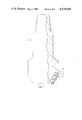
- FIG. 1 is a side view of a drill bit, partly broken away and in section showing cutter elements of the invention in perspective, mounted within the drill bit.
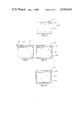
- FIG. 2 is a perspective view, partly broken away and in section of a composite compact bonded to a mounting stud.
- FIG. 3 is a simplified, side view of the apparatus used in the brazing step of the method of the invention.
- FIG. 4 is a simplified, microscopic, cross-sectional view of a composite compact of the invention in the rough state.
- FIG. 5 is a microscopic, cross-sectional view similar to FIG. 2, but showing the thin, metal coating of the invention.
- FIG. 6 is a view similar to FIG. 3, showing a flat, exposed surface of the diamond layer after grinding.
- FIG. 7 is a view similar to FIG. 5 showing a dished-out upper surface of a coated composite compact prior to grinding.
- FIG. 1 shows a drill bit 11 with cutter elements, designated generally as 13.
- Each of the cutter elements 13 includes a mounting stud 15 to which is bonded a composite compact 17.
- the mounting stud 15 is retained within an opening 16 provided in the bit head, as by press-fitting or brazing the stud within the opening.
- Each finished composite compact 17, as shown in FIG. 2, includes a thin, planar layer or mass 19 of bonded abrasive particles of either diamond or hard phase boron nitride having an abrasive surface 21.
- the abrasive mass 19 is bonded to a substrate 23 of cemented carbide along an interface 25.
- the carbide substrate 23 also has an exposed end surface 27 opposite the abrasive surface 21.
- the preferred compacts 17 are commercially available and are described in U.S. Pat. No. 3,745,623.
- Layer 19 is comprised by volume of at least 70% diamond and preferably in excess of 90% diamond.
- the remaining composition is comprised of bonding material, such as cobalt or alloys which have infiltrated into layer 19 during the fabrication process of the compact.
- bonding material such as cobalt or alloys which have infiltrated into layer 19 during the fabrication process of the compact.
- bonding material such as cobalt or alloys which have infiltrated into layer 19 during the fabrication process of the compact.
- other hard abrasive particles such as cubic or hexagonal hard phase boron nitride, can be utilized as the layer 19.
- a process of making such hard phase boron nitride is shown in U.S. Pat. No. 3,743,489 and U.S. Pat. No. 3,767,371.
- the substrate 23 is preferably of cemented carbide. See U.S. Pat. No. 3,745,623, for a description of suitable cemented carbides.
- the cemented carbides are preferred because of their hardness, although ceramics such as alumina or steel can be utilized in some applications.
- the mounting stud 15 is also preferably of cemented carbide, identical to the material of substrate 23.
- the filler metal 29 is preferably a high temperature, high strength brazing filler having a liquidus greater than the degradation temperature of the abrasive particulate mass 19.
- Acceptable filler metals can be chosen from the group of alloys compatible with the materials being brazed.
- a preferred braze filler commercially available is Anaconda 773.
- FIG. 3 shows the parts of an apparatus used for fabricating cutter elements which are relevant to the present invention.
- the apparatus is described in greater detail in U.S. Pat. No. 4,319,707 to Knemeyer, issued Mar. 16, 1982, the disclosure of which is hereby incorporated by reference.
- the apparatus includes a plunger 31 with a suitably shaped end surface 49 for making contact with one end of the composite compact 17.
- Head 33 is provided with a coolant, such as water, circulated through tube 35 from a coolant supply. Head 33 and coolant supply tube 35 form a heat sink for diamond layer 19 during the step of brazing the compact 17 to the mounting stud 15.
- a coolant such as water
- the apparatus of FIG. 3 also includes a cylinder plunger 37 with a head 39 affixed thereto.
- Head 39 has a ceramic insulator 40 positioned thereon to prevent the heat sinking of stud 15 to head 39 during brazing.
- Head 39 is also interconnected to the coolant supply in tube 35.
- An induction heating coil assembly 41 surrounds the mounting stud 15 and compact 17 for providing the heat necessary to braze the materials.
- a shim or powder mixture of brazing filler 29 (FIG. 2) is positioned between the composite compact end 27 and the top surface mounting stud 15 as stud 15 and compact 27 are positioned between the plungers 31, 37.
- the filler 29 is then heated to a temperature above the melting point to melt the filler and firmly bond the compact 17 to the mounting stud 15.
- the plungers are then retracted and the finished cutter element is removed from the apparatus.
- the commercially supplied composite compacts 17 have a rough abrasive surface 21.
- the abrasive surface 21 is shown as being flat in FIG. 4, the surface can also be concave, as shown in FIG. 7, or even convex. As has been described, it is only by contacting the abrasive diamond surface 21 with the cooling head 33 that the temperature of the diamond layer is kept below the thermal degradation point while the brazing is carried out.
- the surface 21 In order that the cooling head 33 might effectively dissipate the heat from the top surface 21 of the compact 17, the surface 21 must be ground perfectly smooth. In the past, this was accomplished by grinding the exposed abrasive surface (21 in FIG. 4) with a diamond grinder or lapping device. This approach to the problem added to the manufacturing cost since diamond surfaces can only be ground smooth by a grinding tool utilizing diamonds as the grinding medium.
- the composite compact 17, as commercially supplied, is first coated with a thin metal layer (43 in FIG. 5).
- the metal selected for coating the composite compact 17 can generally be any metal capable of bonding to the composite compact which is relatively softer to grind than the abrasive surface 21.
- any metal selected from the group consisting of Group I-B, II-B, IV-B, V-B, VI-B, VII-B and VIII, elements of the periodic table of chemical elements and alloys thereof can be used.
- copper is used as a conveniently available, economical coating material.
- the process used to coat the composite compact 17 with the thin metal layer is not critical and any known technique such as electrodeless coating or plating, chemical vapor coating and plasma deposition can be used. It is only necessary that the abrasive surface 21 be coated to a depth sufficient to cover the diamond layer 19, although convenience may dictate that the entire composite compact 17 be coated by a thin metal layer.
- the depth of the film or coating over the abrasive surface 21 is preferably at least about 0.003 inches thick.
- a protective layer is formed which covers any protruding diamonds in the abrasive surface 21.
- the coated diamond surface (45 in FIG. 5) can then be ground to a depth sufficient to form a smooth even surface over the diamond layer 19 by using conventional grinding tools which do not utilize diamond grinder elements.
- the depth to which the coated surface 45 is ground is not critical, as long as the depth is less than the depth of the abrasive diamond surface 21 in the diamond layer 19.
- the coated surface 45 which is left after grinding is illustrated in simplified fashion in FIG. 6. Although the thin metal layer 43 is left in its original thickness around the remainder of the composite compact, it should be understood that the coating could have been applied only to the diamond layer, such as by sputtering, if desired.
- the composite compact 17, as shown in FIG. 6, with a smoothly ground top surface 47, is now placed in the apparatus of FIG. 3 and the cooling head 33 is lowered into contact with the top surface 47. Because the end surface 49 of the cooling head makes contact over the entire exposed top surface of the coated and ground composite compact 17, the diamond layer is cooled during the subsequent brazing operation and is not thermally degraded.
- FIG. 7 illustrates another aspect of the problem toward which the present invention is directed.
- the compacts can be supplied with a dished-out upper surface 51 when viewed in cross section. If the surface 51 were left unground, the cooling head 33 would only make contact with a ring-shaped area around the periphery of surface 51 during the brazing step.
- the compact abrasive surface 51 is coated with a thin metal layer 53.
- the coated surface can then be ground to the level indicated by line 55 in FIG. 7 to provide a smooth surface for contacting the cooling head 33 during brazing.
- An alternate method of grinding compacts having concave or convex diamond coated surfaces is to use a technique which will retain the curvature of the upper surface.
- the end surface 49 of the cooling head 33 would be concave or convex to match the smoothly ground coated surface of the compact. In such cases, the ground, coated surface would look more like layer 53 in FIG. 7.
- An invention has been provided with several advantages.
- a smoothly ground, top surface can be provided for the composite compact which is desirable in subsequent manufacturing operations.
- the smoothly ground surface can be provided by grinding the coated surface to an appropriate depth, utilizing grinding devices which do not require diamond grinding elements. Because the coated metallic layer is softer than the abrasive surface of the composite compact, the grinding operation is less time consuming and more economical.
Abstract
Description
Claims (8)
Priority Applications (3)
| Application Number | Priority Date | Filing Date | Title |
|---|---|---|---|
| US06/608,047 US4539018A (en) | 1984-05-07 | 1984-05-07 | Method of manufacturing cutter elements for drill bits |
| ZA852845A ZA852845B (en) | 1984-05-07 | 1985-04-16 | Method of manufacturing cutter elements for drill bits |
| GB08509840A GB2158744A (en) | 1984-05-07 | 1985-04-17 | Fixing imposite compact of cutter element to mounting stud |
Applications Claiming Priority (1)
| Application Number | Priority Date | Filing Date | Title |
|---|---|---|---|
| US06/608,047 US4539018A (en) | 1984-05-07 | 1984-05-07 | Method of manufacturing cutter elements for drill bits |
Publications (1)
| Publication Number | Publication Date |
|---|---|
| US4539018A true US4539018A (en) | 1985-09-03 |
Family
ID=24434801
Family Applications (1)
| Application Number | Title | Priority Date | Filing Date |
|---|---|---|---|
| US06/608,047 Expired - Fee Related US4539018A (en) | 1984-05-07 | 1984-05-07 | Method of manufacturing cutter elements for drill bits |
Country Status (3)
| Country | Link |
|---|---|
| US (1) | US4539018A (en) |
| GB (1) | GB2158744A (en) |
| ZA (1) | ZA852845B (en) |
Cited By (37)
| Publication number | Priority date | Publication date | Assignee | Title |
|---|---|---|---|---|
| US4605343A (en) * | 1984-09-20 | 1986-08-12 | General Electric Company | Sintered polycrystalline diamond compact construction with integral heat sink |
| US4719979A (en) * | 1986-03-24 | 1988-01-19 | Smith International, Inc. | Expendable diamond drag bit |
| US4813500A (en) * | 1987-10-19 | 1989-03-21 | Smith International, Inc. | Expendable diamond drag bit |
| US4943488A (en) * | 1986-10-20 | 1990-07-24 | Norton Company | Low pressure bonding of PCD bodies and method for drill bits and the like |
| US4995887A (en) * | 1988-04-05 | 1991-02-26 | Reed Tool Company Limited | Cutting elements for rotary drill bits |
| US5011514A (en) * | 1988-07-29 | 1991-04-30 | Norton Company | Cemented and cemented/sintered superabrasive polycrystalline bodies and methods of manufacture thereof |
| US5030276A (en) * | 1986-10-20 | 1991-07-09 | Norton Company | Low pressure bonding of PCD bodies and method |
| US5061293A (en) * | 1989-04-04 | 1991-10-29 | Barr John D | Cutting elements for rotary drill bits |
| US5062865A (en) * | 1987-12-04 | 1991-11-05 | Norton Company | Chemically bonded superabrasive grit |
| US5090969A (en) * | 1987-10-21 | 1992-02-25 | Takeo Oki | Coated abrasive grains and a manufacturing method therefor |
| US5103922A (en) * | 1990-10-30 | 1992-04-14 | Smith International, Inc. | Fishtail expendable diamond drag bit |
| US5116568A (en) * | 1986-10-20 | 1992-05-26 | Norton Company | Method for low pressure bonding of PCD bodies |
| GB2251880A (en) * | 1988-04-05 | 1992-07-22 | Camco Drilling Group Ltd | Manufacturing cutting elements for rotary drill bits |
| US5151107A (en) * | 1988-07-29 | 1992-09-29 | Norton Company | Cemented and cemented/sintered superabrasive polycrystalline bodies and methods of manufacture thereof |
| US5173091A (en) * | 1991-06-04 | 1992-12-22 | General Electric Company | Chemically bonded adherent coating for abrasive compacts and method for making same |
| EP0656458A2 (en) * | 1993-11-22 | 1995-06-07 | Baker Hughes Incorporated | Superhard cutting element having reduced surface roughness |
| GB2311084A (en) * | 1996-03-12 | 1997-09-17 | Smith International | Polycrystalline diamond cutter coated in a refractory material |
| US6439327B1 (en) * | 2000-08-24 | 2002-08-27 | Camco International (Uk) Limited | Cutting elements for rotary drill bits |
| US20020119303A1 (en) * | 2001-02-26 | 2002-08-29 | General Electric Company | Metal-infiltrated polycrystalline diamond composite tool formed from coated diamond particles |
| US20060157286A1 (en) * | 2005-01-17 | 2006-07-20 | Us Synthetic | Superabrasive inserts including an arcuate peripheral surface |
| US7108598B1 (en) | 2001-07-09 | 2006-09-19 | U.S. Synthetic Corporation | PDC interface incorporating a closed network of features |
| US20060254830A1 (en) * | 2005-05-16 | 2006-11-16 | Smith International, Inc. | Thermally stable diamond brazing |
| US8511405B2 (en) * | 2010-04-30 | 2013-08-20 | Ryan Clint Frazier | Drill bit with tiered cutters |
| US8684112B2 (en) | 2010-04-23 | 2014-04-01 | Baker Hughes Incorporated | Cutting elements for earth-boring tools, earth-boring tools including such cutting elements and related methods |
| US8777088B2 (en) * | 2011-09-16 | 2014-07-15 | Baker Hughes Incorporated | Methods for attaching cutting elements to earth-boring tools using tapered surfaces |
| US8789627B1 (en) | 2005-07-17 | 2014-07-29 | Us Synthetic Corporation | Polycrystalline diamond cutter with improved abrasion and impact resistance and method of making the same |
| US8936659B2 (en) | 2010-04-14 | 2015-01-20 | Baker Hughes Incorporated | Methods of forming diamond particles having organic compounds attached thereto and compositions thereof |
| US9103174B2 (en) | 2011-04-22 | 2015-08-11 | Baker Hughes Incorporated | Cutting elements for earth-boring tools, earth-boring tools including such cutting elements and related methods |
| US9140072B2 (en) | 2013-02-28 | 2015-09-22 | Baker Hughes Incorporated | Cutting elements including non-planar interfaces, earth-boring tools including such cutting elements, and methods of forming cutting elements |
| US9194189B2 (en) | 2011-09-19 | 2015-11-24 | Baker Hughes Incorporated | Methods of forming a cutting element for an earth-boring tool, a related cutting element, and an earth-boring tool including such a cutting element |
| US9243452B2 (en) | 2011-04-22 | 2016-01-26 | Baker Hughes Incorporated | Cutting elements for earth-boring tools, earth-boring tools including such cutting elements, and related methods |
| US9376867B2 (en) | 2011-09-16 | 2016-06-28 | Baker Hughes Incorporated | Methods of drilling a subterranean bore hole |
| US9428966B2 (en) | 2012-05-01 | 2016-08-30 | Baker Hughes Incorporated | Cutting elements for earth-boring tools, earth-boring tools including such cutting elements, and related methods |
| US9650837B2 (en) | 2011-04-22 | 2017-05-16 | Baker Hughes Incorporated | Multi-chamfer cutting elements having a shaped cutting face and earth-boring tools including such cutting elements |
| US9821437B2 (en) | 2012-05-01 | 2017-11-21 | Baker Hughes Incorporated | Earth-boring tools having cutting elements with cutting faces exhibiting multiple coefficients of friction, and related methods |
| US10307891B2 (en) | 2015-08-12 | 2019-06-04 | Us Synthetic Corporation | Attack inserts with differing surface finishes, assemblies, systems including same, and related methods |
| US10900291B2 (en) | 2017-09-18 | 2021-01-26 | Us Synthetic Corporation | Polycrystalline diamond elements and systems and methods for fabricating the same |
Families Citing this family (16)
| Publication number | Priority date | Publication date | Assignee | Title |
|---|---|---|---|---|
| US8637127B2 (en) | 2005-06-27 | 2014-01-28 | Kennametal Inc. | Composite article with coolant channels and tool fabrication method |
| US7687156B2 (en) | 2005-08-18 | 2010-03-30 | Tdy Industries, Inc. | Composite cutting inserts and methods of making the same |
| US8312941B2 (en) | 2006-04-27 | 2012-11-20 | TDY Industries, LLC | Modular fixed cutter earth-boring bits, modular fixed cutter earth-boring bit bodies, and related methods |
| US8007922B2 (en) | 2006-10-25 | 2011-08-30 | Tdy Industries, Inc | Articles having improved resistance to thermal cracking |
| US8512882B2 (en) | 2007-02-19 | 2013-08-20 | TDY Industries, LLC | Carbide cutting insert |
| US7846551B2 (en) | 2007-03-16 | 2010-12-07 | Tdy Industries, Inc. | Composite articles |
| US8790439B2 (en) | 2008-06-02 | 2014-07-29 | Kennametal Inc. | Composite sintered powder metal articles |
| CN102112642B (en) | 2008-06-02 | 2013-11-06 | Tdy工业有限责任公司 | Cemented carbide-metallic alloy composites |
| US8025112B2 (en) | 2008-08-22 | 2011-09-27 | Tdy Industries, Inc. | Earth-boring bits and other parts including cemented carbide |
| US8322465B2 (en) | 2008-08-22 | 2012-12-04 | TDY Industries, LLC | Earth-boring bit parts including hybrid cemented carbides and methods of making the same |
| US8272816B2 (en) | 2009-05-12 | 2012-09-25 | TDY Industries, LLC | Composite cemented carbide rotary cutting tools and rotary cutting tool blanks |
| US8308096B2 (en) | 2009-07-14 | 2012-11-13 | TDY Industries, LLC | Reinforced roll and method of making same |
| US8440314B2 (en) | 2009-08-25 | 2013-05-14 | TDY Industries, LLC | Coated cutting tools having a platinum group metal concentration gradient and related processes |
| US9643236B2 (en) | 2009-11-11 | 2017-05-09 | Landis Solutions Llc | Thread rolling die and method of making same |
| US8800848B2 (en) | 2011-08-31 | 2014-08-12 | Kennametal Inc. | Methods of forming wear resistant layers on metallic surfaces |
| US9016406B2 (en) | 2011-09-22 | 2015-04-28 | Kennametal Inc. | Cutting inserts for earth-boring bits |
Citations (17)
| Publication number | Priority date | Publication date | Assignee | Title |
|---|---|---|---|---|
| US2200281A (en) * | 1937-07-28 | 1940-05-14 | Charles J Koebel | Art of setting diamonds for industrial purposes |
| US3233988A (en) * | 1964-05-19 | 1966-02-08 | Gen Electric | Cubic boron nitride compact and method for its production |
| US3609818A (en) * | 1970-01-02 | 1971-10-05 | Gen Electric | Reaction vessel for high pressure apparatus |
| US3743489A (en) * | 1971-07-01 | 1973-07-03 | Gen Electric | Abrasive bodies of finely-divided cubic boron nitride crystals |
| US3745623A (en) * | 1971-12-27 | 1973-07-17 | Gen Electric | Diamond tools for machining |
| US3767371A (en) * | 1971-07-01 | 1973-10-23 | Gen Electric | Cubic boron nitride/sintered carbide abrasive bodies |
| US3894673A (en) * | 1971-11-04 | 1975-07-15 | Abrasive Tech Inc | Method of manufacturing diamond abrasive tools |
| US4006788A (en) * | 1975-06-11 | 1977-02-08 | Smith International, Inc. | Diamond cutter rock bit with penetration limiting |
| US4063909A (en) * | 1974-09-18 | 1977-12-20 | Robert Dennis Mitchell | Abrasive compact brazed to a backing |
| US4140189A (en) * | 1977-06-06 | 1979-02-20 | Smith International, Inc. | Rock bit with diamond reamer to maintain gage |
| US4151889A (en) * | 1976-07-13 | 1979-05-01 | William Lister | Rock-drilling bit for percussion hammers |
| US4156329A (en) * | 1977-05-13 | 1979-05-29 | General Electric Company | Method for fabricating a rotary drill bit and composite compact cutters therefor |
| US4199035A (en) * | 1978-04-24 | 1980-04-22 | General Electric Company | Cutting and drilling apparatus with threadably attached compacts |
| US4221270A (en) * | 1978-12-18 | 1980-09-09 | Smith International, Inc. | Drag bit |
| US4225322A (en) * | 1978-01-10 | 1980-09-30 | General Electric Company | Composite compact components fabricated with high temperature brazing filler metal and method for making same |
| US4319707A (en) * | 1978-01-10 | 1982-03-16 | General Electric Company | Brazing apparatus to manufacture composite compact components |
| US4325439A (en) * | 1979-05-02 | 1982-04-20 | Smith International, Inc. | Diamond insert stud for a drag bit |
-
1984
- 1984-05-07 US US06/608,047 patent/US4539018A/en not_active Expired - Fee Related
-
1985
- 1985-04-16 ZA ZA852845A patent/ZA852845B/en unknown
- 1985-04-17 GB GB08509840A patent/GB2158744A/en not_active Withdrawn
Patent Citations (17)
| Publication number | Priority date | Publication date | Assignee | Title |
|---|---|---|---|---|
| US2200281A (en) * | 1937-07-28 | 1940-05-14 | Charles J Koebel | Art of setting diamonds for industrial purposes |
| US3233988A (en) * | 1964-05-19 | 1966-02-08 | Gen Electric | Cubic boron nitride compact and method for its production |
| US3609818A (en) * | 1970-01-02 | 1971-10-05 | Gen Electric | Reaction vessel for high pressure apparatus |
| US3743489A (en) * | 1971-07-01 | 1973-07-03 | Gen Electric | Abrasive bodies of finely-divided cubic boron nitride crystals |
| US3767371A (en) * | 1971-07-01 | 1973-10-23 | Gen Electric | Cubic boron nitride/sintered carbide abrasive bodies |
| US3894673A (en) * | 1971-11-04 | 1975-07-15 | Abrasive Tech Inc | Method of manufacturing diamond abrasive tools |
| US3745623A (en) * | 1971-12-27 | 1973-07-17 | Gen Electric | Diamond tools for machining |
| US4063909A (en) * | 1974-09-18 | 1977-12-20 | Robert Dennis Mitchell | Abrasive compact brazed to a backing |
| US4006788A (en) * | 1975-06-11 | 1977-02-08 | Smith International, Inc. | Diamond cutter rock bit with penetration limiting |
| US4151889A (en) * | 1976-07-13 | 1979-05-01 | William Lister | Rock-drilling bit for percussion hammers |
| US4156329A (en) * | 1977-05-13 | 1979-05-29 | General Electric Company | Method for fabricating a rotary drill bit and composite compact cutters therefor |
| US4140189A (en) * | 1977-06-06 | 1979-02-20 | Smith International, Inc. | Rock bit with diamond reamer to maintain gage |
| US4225322A (en) * | 1978-01-10 | 1980-09-30 | General Electric Company | Composite compact components fabricated with high temperature brazing filler metal and method for making same |
| US4319707A (en) * | 1978-01-10 | 1982-03-16 | General Electric Company | Brazing apparatus to manufacture composite compact components |
| US4199035A (en) * | 1978-04-24 | 1980-04-22 | General Electric Company | Cutting and drilling apparatus with threadably attached compacts |
| US4221270A (en) * | 1978-12-18 | 1980-09-09 | Smith International, Inc. | Drag bit |
| US4325439A (en) * | 1979-05-02 | 1982-04-20 | Smith International, Inc. | Diamond insert stud for a drag bit |
Cited By (65)
| Publication number | Priority date | Publication date | Assignee | Title |
|---|---|---|---|---|
| US4605343A (en) * | 1984-09-20 | 1986-08-12 | General Electric Company | Sintered polycrystalline diamond compact construction with integral heat sink |
| US4719979A (en) * | 1986-03-24 | 1988-01-19 | Smith International, Inc. | Expendable diamond drag bit |
| US5030276A (en) * | 1986-10-20 | 1991-07-09 | Norton Company | Low pressure bonding of PCD bodies and method |
| US4943488A (en) * | 1986-10-20 | 1990-07-24 | Norton Company | Low pressure bonding of PCD bodies and method for drill bits and the like |
| US5116568A (en) * | 1986-10-20 | 1992-05-26 | Norton Company | Method for low pressure bonding of PCD bodies |
| US4813500A (en) * | 1987-10-19 | 1989-03-21 | Smith International, Inc. | Expendable diamond drag bit |
| US5090969A (en) * | 1987-10-21 | 1992-02-25 | Takeo Oki | Coated abrasive grains and a manufacturing method therefor |
| US5062865A (en) * | 1987-12-04 | 1991-11-05 | Norton Company | Chemically bonded superabrasive grit |
| US4995887A (en) * | 1988-04-05 | 1991-02-26 | Reed Tool Company Limited | Cutting elements for rotary drill bits |
| GB2216929B (en) * | 1988-04-05 | 1992-11-04 | Reed Tool Co | Improvements in or relating to cutting elements for rotary drill bits |
| GB2251880B (en) * | 1988-04-05 | 1992-11-04 | Camco Drilling Group Ltd | Improvements in or relating to cutting elements for rotary drill bits |
| GB2251880A (en) * | 1988-04-05 | 1992-07-22 | Camco Drilling Group Ltd | Manufacturing cutting elements for rotary drill bits |
| US5011514A (en) * | 1988-07-29 | 1991-04-30 | Norton Company | Cemented and cemented/sintered superabrasive polycrystalline bodies and methods of manufacture thereof |
| US5151107A (en) * | 1988-07-29 | 1992-09-29 | Norton Company | Cemented and cemented/sintered superabrasive polycrystalline bodies and methods of manufacture thereof |
| US5061293A (en) * | 1989-04-04 | 1991-10-29 | Barr John D | Cutting elements for rotary drill bits |
| US5103922A (en) * | 1990-10-30 | 1992-04-14 | Smith International, Inc. | Fishtail expendable diamond drag bit |
| US5173091A (en) * | 1991-06-04 | 1992-12-22 | General Electric Company | Chemically bonded adherent coating for abrasive compacts and method for making same |
| US6145608A (en) * | 1993-11-22 | 2000-11-14 | Baker Hughes Incorporated | Superhard cutting structure having reduced surface roughness and bit for subterranean drilling so equipped |
| EP0656458A3 (en) * | 1993-11-22 | 1996-11-06 | Baker Hughes Inc | Superhard cutting element having reduced surface roughness. |
| US5653300A (en) * | 1993-11-22 | 1997-08-05 | Baker Hughes Incorporated | Modified superhard cutting elements having reduced surface roughness method of modifying, drill bits equipped with such cutting elements, and methods of drilling therewith |
| US5967250A (en) * | 1993-11-22 | 1999-10-19 | Baker Hughes Incorporated | Modified superhard cutting element having reduced surface roughness and method of modifying |
| EP0656458A2 (en) * | 1993-11-22 | 1995-06-07 | Baker Hughes Incorporated | Superhard cutting element having reduced surface roughness |
| GB2311084A (en) * | 1996-03-12 | 1997-09-17 | Smith International | Polycrystalline diamond cutter coated in a refractory material |
| US5833021A (en) * | 1996-03-12 | 1998-11-10 | Smith International, Inc. | Surface enhanced polycrystalline diamond composite cutters |
| GB2311084B (en) * | 1996-03-12 | 2000-06-14 | Smith International | Surface enhanced polycrystallline diamond composite cutters |
| US6439327B1 (en) * | 2000-08-24 | 2002-08-27 | Camco International (Uk) Limited | Cutting elements for rotary drill bits |
| US20020119303A1 (en) * | 2001-02-26 | 2002-08-29 | General Electric Company | Metal-infiltrated polycrystalline diamond composite tool formed from coated diamond particles |
| US6541115B2 (en) * | 2001-02-26 | 2003-04-01 | General Electric Company | Metal-infiltrated polycrystalline diamond composite tool formed from coated diamond particles |
| US7108598B1 (en) | 2001-07-09 | 2006-09-19 | U.S. Synthetic Corporation | PDC interface incorporating a closed network of features |
| US20090272583A1 (en) * | 2005-01-17 | 2009-11-05 | Us Synthetic Corporation | Superabrasive inserts including an arcuate peripheral surface |
| US8783388B1 (en) | 2005-01-17 | 2014-07-22 | Us Synthetic Corporation | Superabrasive inserts including an arcuate peripheral surface |
| US7475744B2 (en) | 2005-01-17 | 2009-01-13 | Us Synthetic Corporation | Superabrasive inserts including an arcuate peripheral surface |
| US8505655B1 (en) | 2005-01-17 | 2013-08-13 | Us Synthetic Corporation | Superabrasive inserts including an arcuate peripheral surface |
| US20060157286A1 (en) * | 2005-01-17 | 2006-07-20 | Us Synthetic | Superabrasive inserts including an arcuate peripheral surface |
| US8272459B2 (en) | 2005-01-17 | 2012-09-25 | Us Synthetic Corporation | Superabrasive inserts including an arcuate peripheral surface |
| US7487849B2 (en) * | 2005-05-16 | 2009-02-10 | Radtke Robert P | Thermally stable diamond brazing |
| US20060254830A1 (en) * | 2005-05-16 | 2006-11-16 | Smith International, Inc. | Thermally stable diamond brazing |
| US8789627B1 (en) | 2005-07-17 | 2014-07-29 | Us Synthetic Corporation | Polycrystalline diamond cutter with improved abrasion and impact resistance and method of making the same |
| US8936659B2 (en) | 2010-04-14 | 2015-01-20 | Baker Hughes Incorporated | Methods of forming diamond particles having organic compounds attached thereto and compositions thereof |
| US8684112B2 (en) | 2010-04-23 | 2014-04-01 | Baker Hughes Incorporated | Cutting elements for earth-boring tools, earth-boring tools including such cutting elements and related methods |
| US10006253B2 (en) | 2010-04-23 | 2018-06-26 | Baker Hughes Incorporated | Cutting elements for earth-boring tools and earth-boring tools including such cutting elements |
| US8919462B2 (en) | 2010-04-23 | 2014-12-30 | Baker Hughes Incorporated | Cutting elements for earth-boring tools, earth-boring tools including such cutting elements and related methods |
| US8511405B2 (en) * | 2010-04-30 | 2013-08-20 | Ryan Clint Frazier | Drill bit with tiered cutters |
| US9243452B2 (en) | 2011-04-22 | 2016-01-26 | Baker Hughes Incorporated | Cutting elements for earth-boring tools, earth-boring tools including such cutting elements, and related methods |
| US9650837B2 (en) | 2011-04-22 | 2017-05-16 | Baker Hughes Incorporated | Multi-chamfer cutting elements having a shaped cutting face and earth-boring tools including such cutting elements |
| US10428591B2 (en) | 2011-04-22 | 2019-10-01 | Baker Hughes Incorporated | Structures for drilling a subterranean formation |
| US9103174B2 (en) | 2011-04-22 | 2015-08-11 | Baker Hughes Incorporated | Cutting elements for earth-boring tools, earth-boring tools including such cutting elements and related methods |
| US10337255B2 (en) | 2011-04-22 | 2019-07-02 | Baker Hughes Incorporated | Cutting elements for earth-boring tools, earth-boring tools including such cutting elements, and related methods |
| US9482057B2 (en) | 2011-09-16 | 2016-11-01 | Baker Hughes Incorporated | Cutting elements for earth-boring tools, earth-boring tools including such cutting elements and related methods |
| US9376867B2 (en) | 2011-09-16 | 2016-06-28 | Baker Hughes Incorporated | Methods of drilling a subterranean bore hole |
| US9617792B2 (en) | 2011-09-16 | 2017-04-11 | Baker Hughes Incorporated | Cutting elements for earth-boring tools, earth-boring tools including such cutting elements and related methods |
| US10428590B2 (en) | 2011-09-16 | 2019-10-01 | Baker Hughes, A Ge Company, Llc | Cutting elements for earth-boring tools and earth-boring tools including such cutting elements |
| US8777088B2 (en) * | 2011-09-16 | 2014-07-15 | Baker Hughes Incorporated | Methods for attaching cutting elements to earth-boring tools using tapered surfaces |
| US10385623B2 (en) | 2011-09-16 | 2019-08-20 | Baker Hughes, A Ge Company, Llc | Cutting elements for earth-boring tools and earth-boring tools including such cutting elements |
| US9771497B2 (en) | 2011-09-19 | 2017-09-26 | Baker Hughes, A Ge Company, Llc | Methods of forming earth-boring tools |
| US9194189B2 (en) | 2011-09-19 | 2015-11-24 | Baker Hughes Incorporated | Methods of forming a cutting element for an earth-boring tool, a related cutting element, and an earth-boring tool including such a cutting element |
| US9821437B2 (en) | 2012-05-01 | 2017-11-21 | Baker Hughes Incorporated | Earth-boring tools having cutting elements with cutting faces exhibiting multiple coefficients of friction, and related methods |
| US10066442B2 (en) | 2012-05-01 | 2018-09-04 | Baker Hughes Incorporated | Cutting elements for earth-boring tools, earth-boring tools including such cutting elements, and related methods |
| US9428966B2 (en) | 2012-05-01 | 2016-08-30 | Baker Hughes Incorporated | Cutting elements for earth-boring tools, earth-boring tools including such cutting elements, and related methods |
| US11229989B2 (en) | 2012-05-01 | 2022-01-25 | Baker Hughes Holdings Llc | Methods of forming cutting elements with cutting faces exhibiting multiple coefficients of friction, and related methods |
| US9140072B2 (en) | 2013-02-28 | 2015-09-22 | Baker Hughes Incorporated | Cutting elements including non-planar interfaces, earth-boring tools including such cutting elements, and methods of forming cutting elements |
| US10307891B2 (en) | 2015-08-12 | 2019-06-04 | Us Synthetic Corporation | Attack inserts with differing surface finishes, assemblies, systems including same, and related methods |
| US11583978B2 (en) | 2015-08-12 | 2023-02-21 | Us Synthetic Corporation | Attack inserts with differing surface finishes, assemblies, systems including same, and related methods |
| US10900291B2 (en) | 2017-09-18 | 2021-01-26 | Us Synthetic Corporation | Polycrystalline diamond elements and systems and methods for fabricating the same |
| US11946320B2 (en) | 2017-09-18 | 2024-04-02 | Us Synthetic Corporation | Polycrystalline diamond elements and systems and methods for fabricating the same |
Also Published As
| Publication number | Publication date |
|---|---|
| GB2158744A (en) | 1985-11-20 |
| ZA852845B (en) | 1985-11-27 |
| GB8509840D0 (en) | 1985-05-22 |
Similar Documents
| Publication | Publication Date | Title |
|---|---|---|
| US4539018A (en) | Method of manufacturing cutter elements for drill bits | |
| US4156329A (en) | Method for fabricating a rotary drill bit and composite compact cutters therefor | |
| EP0264674B1 (en) | Low pressure bonding of PCD bodies and method | |
| CA1119006A (en) | Composite compact components fabricated with high temperature filler metal and method of making same | |
| US5096465A (en) | Diamond metal composite cutter and method for making same | |
| US5030276A (en) | Low pressure bonding of PCD bodies and method | |
| US4943488A (en) | Low pressure bonding of PCD bodies and method for drill bits and the like | |
| EP0418078B1 (en) | Composite abrasive compacts | |
| US5116568A (en) | Method for low pressure bonding of PCD bodies | |
| EP0437855B1 (en) | Integral matrix body, method and infiltration alloy for making same | |
| US5662720A (en) | Composite polycrystalline diamond compact | |
| CA1275175C (en) | Polycrystalline diamond and cbn cutting tools | |
| US4976324A (en) | Drill bit having diamond film cutting surface | |
| US5011515A (en) | Composite polycrystalline diamond compact with improved impact resistance | |
| EP0185537B1 (en) | Improvements in or relating to cutting structures for rotary drill bits | |
| EP0090657B1 (en) | A method of making abrasive bodies | |
| EP1116858B1 (en) | Insert | |
| US4797138A (en) | Polycrystalline diamond and CBN cutting tools | |
| US4319707A (en) | Brazing apparatus to manufacture composite compact components | |
| CA2033608A1 (en) | Multilayer coated abrasive element for bonding to a backing | |
| EP0029535A1 (en) | Compacts for diamond drill and saw applications | |
| KR20120016255A (en) | Method to attach or improve the attachment of articles | |
| CA2380539C (en) | A drill bit having large diameter pdc cutters | |
| US4781256A (en) | Cutting structures for rotary drill bits | |
| US20030183426A1 (en) | Polycrystalline Material Element with Improved Wear Resistance And Methods of Manufacture Thereof |
Legal Events
| Date | Code | Title | Description |
|---|---|---|---|
| AS | Assignment |
Owner name: HUGHES TOOL COMPANY P.O. BOX 2539 HOUSTON, TX 770 Free format text: ASSIGNMENT OF ASSIGNORS INTEREST.;ASSIGNORS:WHANGER, JAMES R.;STAUDENMAYER, RALPH;REEL/FRAME:004296/0036 Effective date: 19840424 Owner name: HUGHES TOOL COMPANY P.O. BOX 2539 HOUSTON, TX 770 Free format text: ASSIGNMENT OF ASSIGNORS INTEREST.;ASSIGNOR:STAUDENMAYER, RALPH;REEL/FRAME:004296/0034 Effective date: 19840418 |
|
| FEPP | Fee payment procedure |
Free format text: PAYOR NUMBER ASSIGNED (ORIGINAL EVENT CODE: ASPN); ENTITY STATUS OF PATENT OWNER: LARGE ENTITY |
|
| FPAY | Fee payment |
Year of fee payment: 4 |
|
| FEPP | Fee payment procedure |
Free format text: PAYOR NUMBER ASSIGNED (ORIGINAL EVENT CODE: ASPN); ENTITY STATUS OF PATENT OWNER: LARGE ENTITY Free format text: PAYER NUMBER DE-ASSIGNED (ORIGINAL EVENT CODE: RMPN); ENTITY STATUS OF PATENT OWNER: LARGE ENTITY |
|
| LAPS | Lapse for failure to pay maintenance fees | ||
| FP | Lapsed due to failure to pay maintenance fee |
Effective date: 19930905 |
|
| STCH | Information on status: patent discontinuation |
Free format text: PATENT EXPIRED DUE TO NONPAYMENT OF MAINTENANCE FEES UNDER 37 CFR 1.362 |