US4537357A - Spray guns - Google Patents
Spray guns Download PDFInfo
- Publication number
- US4537357A US4537357A US06/658,209 US65820984A US4537357A US 4537357 A US4537357 A US 4537357A US 65820984 A US65820984 A US 65820984A US 4537357 A US4537357 A US 4537357A
- Authority
- US
- United States
- Prior art keywords
- fluid
- air
- nozzle
- fluid nozzle
- spray
- Prior art date
- Legal status (The legal status is an assumption and is not a legal conclusion. Google has not performed a legal analysis and makes no representation as to the accuracy of the status listed.)
- Expired - Lifetime
Links
Images


Classifications
-
- B—PERFORMING OPERATIONS; TRANSPORTING
- B05—SPRAYING OR ATOMISING IN GENERAL; APPLYING FLUENT MATERIALS TO SURFACES, IN GENERAL
- B05B—SPRAYING APPARATUS; ATOMISING APPARATUS; NOZZLES
- B05B7/00—Spraying apparatus for discharge of liquids or other fluent materials from two or more sources, e.g. of liquid and air, of powder and gas
- B05B7/02—Spray pistols; Apparatus for discharge
- B05B7/08—Spray pistols; Apparatus for discharge with separate outlet orifices, e.g. to form parallel jets, i.e. the axis of the jets being parallel, to form intersecting jets, i.e. the axis of the jets converging but not necessarily intersecting at a point
- B05B7/0807—Spray pistols; Apparatus for discharge with separate outlet orifices, e.g. to form parallel jets, i.e. the axis of the jets being parallel, to form intersecting jets, i.e. the axis of the jets converging but not necessarily intersecting at a point to form intersecting jets
- B05B7/0815—Spray pistols; Apparatus for discharge with separate outlet orifices, e.g. to form parallel jets, i.e. the axis of the jets being parallel, to form intersecting jets, i.e. the axis of the jets converging but not necessarily intersecting at a point to form intersecting jets with at least one gas jet intersecting a jet constituted by a liquid or a mixture containing a liquid for controlling the shape of the latter
-
- B—PERFORMING OPERATIONS; TRANSPORTING
- B05—SPRAYING OR ATOMISING IN GENERAL; APPLYING FLUENT MATERIALS TO SURFACES, IN GENERAL
- B05B—SPRAYING APPARATUS; ATOMISING APPARATUS; NOZZLES
- B05B15/00—Details of spraying plant or spraying apparatus not otherwise provided for; Accessories
- B05B15/14—Arrangements for preventing or controlling structural damage to spraying apparatus or its outlets, e.g. for breaking at desired places; Arrangements for handling or replacing damaged parts
- B05B15/18—Arrangements for preventing or controlling structural damage to spraying apparatus or its outlets, e.g. for breaking at desired places; Arrangements for handling or replacing damaged parts for improving resistance to wear, e.g. inserts or coatings; for indicating wear; for handling or replacing worn parts
-
- B—PERFORMING OPERATIONS; TRANSPORTING
- B05—SPRAYING OR ATOMISING IN GENERAL; APPLYING FLUENT MATERIALS TO SURFACES, IN GENERAL
- B05B—SPRAYING APPARATUS; ATOMISING APPARATUS; NOZZLES
- B05B7/00—Spraying apparatus for discharge of liquids or other fluent materials from two or more sources, e.g. of liquid and air, of powder and gas
- B05B7/02—Spray pistols; Apparatus for discharge
Definitions
- the present invention relates to spray guns in general, and in particular to improved spray guns having a spray head assembly comprising separate but interconnectable elements mounted on a foward end of the gun body without threaded attachment to the body.
- Fluid passages through the head of a spray gun are desirably of a corrosion and wear resistant material for protection against various types of coating mterials.
- Prior approaches to corrosion and wear protection usually contemplated either use of a separate and removable corrosion resistant head casting or threading a stainless steel insert and a stainless steel fluid inlet insert into the gun head at right angles to each other, machining the inserts while in place to form fluid passages and then securing them in position with epoxy.
- a problem encountered in the former approach is that a compromise occurs in weight and balance considerations that are important to the "feel" of a spray gun, and in the latter loosening of the epoxy often occurs when a gun is soaked in solvent for an extended period.
- threads for receiving an air cap for mounting an air nozzle on the head of the gun are usually formed on the gun body, which arrangement presents difficulties in that the threads are susceptible to damage, and if damaged the gun body, which is essentially the entire gun, is ruined and requires replacement.
- the spray head assemblies are comprised of separate but interconnectable elements including a fluid nozzle, a fluid inlet fitting, a fluid nozzle retainer, an air nozzle and an air cap. Since the elements are separate from the body, the fluid inlet fitting and fluid nozzle may conveniently be manufactured from a corrosion and wear resistant material, and the arrangement of the components offers significant improvements in weight, feel, maintenance and reliability.
- the components may readily be assembled on the forward end of the gun without need for any machining or compromises in the "feel" of the gun, and the fluid nozzle retainer itself, not the gun body, has threads for receiving the air cap for mounting the air nozzle on the gun. Consequently, should the threads be damaged, only the fluid nozzle retainer, and not the substantial entirety of the gun, needs to be replaced.
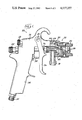
- FIG. 1 is a side elevation view, partly in cross section, illustrating an air spray gun having an improved spray head assembly in accordance with one embodiment of the present invention
- FIG. 2 is an exploded cross sectional view of the spray head assembly shown in FIG. 1;
- FIG. 3 is a cross sectional assembly view of the spray head assembly of FIG. 2;
- FIG. 4 is a cross sectional view of a spray head assembly in accordance with another embodiment of the invention.
- FIG. 5 is a cross sectional assembly view of the spray head assembly of FIG. 4.
- a spray gun assembly including a spray gun 22 having a handle 24 adapted for connection at its lower end with a source of compressed air through a fitting 26.
- the gun has an air nozzle 28 and fluid nozzle means, indicated generally at 30, through which fluid provided to the gun through an inlet fitting 32 is disposed for being atomized into a spray and formed into a fan-shaped pattern by jets of air emitted from the air nozzle.
- an air valve means 34 is movable between open and closed positions to control a flow of pressurized air through the gun
- a fluid valve stem 36 is movable between open and closed positions to control a flow of fluid through the fluid nozzle means
- a manually manipulatable trigger 38 is operably connected with the valve means and stem.
- the trigger is mounted at an upper end by a pivot pin 40 and is manually movable between a gun off position away from the handle whereat the air valve means and fluid valve are closed, to a gun on position toward the handle whereat the air valve means and fluid valve are open and a spray of material is emitted.
- Adjustment of an air control knob 42 determines the amount of atomizing air emitted when the gun is on and adjustment of a fluid control knob 44 determines the dispensing rate of material.
- the spray gun assembly is known in the art and, if conventional and having corrosion and wear resistant fluid passageways, would ordinarily be provided either with a corrosion and wear resistant spray head casting or a stainless steel fluid inlet and outlet inserts threaded into the head of the gun at right angles to each other, machined while in the gun to form the fluid passage and secured in place by epoxy.
- a problem encountered in the former approach is that a compromise occurs in the weight and balance considerations that are important to the "feel" of the gun, and in the latter loosening of the epoxy often occurs when the gun is soaked in solvent for an extended period of time.
- the threads for receiving an air cap for mounting an air nozzle are usually formed on the aluminum gun body, which presents difficulties in that aluminum threads are relatively susceptible to damage, and if damaged then the entire gun body is ruined.
- the spray head assembly comprises separate but interconnectable elements including a fluid nozzle, a fluid nozzle retainer and a fluid inlet fitting, which because they are separate enable the fluid nozzle and fluid inlet fitting to conveniently be manufactured out of a corrosion and wear resistant material.
- the elements may readily be mounted on the forward end of the gun body without threaded attachment to the body, and provide leakproof fluid passages without need for any separate machining or compromises in the "feel" of the gun.
- the fluid nozzle retainer itself not the gun body, has threads for mounting an air cap, so that should the threads be damaged only the nozzle retainer needs replacement and not the substantial entirety of the spray gun.
- an improved spray head assembly is mounted on a downwardly depending annular extension 48 at a forward end of a body portion 50 of the gun.
- the spray head assembly is for an air spray gun and comprises the air nozzle 28 and the fluid inlet fitting 32, together with a fluid nozzle 52, a fluid nozzle retainer 54 and an air cap 56.
- the inlet fitting and fluid nozzle have respective fluid passages 58 and 60 and are of a material which is corrosion and wear resistant to fluids conveyed through the passages, for example a material such as stainless steel or hardened steel.
- the inlet fitting 32 is generally L-shaped and the annular extension 48 has a passage 62 therethrough which has a relatively small diameter at its inner end, increases in diameter toward its outer end and defines two tapered annular shoulders 64 and 66.
- One leg of the inlet fitting has external threads 68 and is extendable through the passage for connection with internal threads 70 in the fluid nozzle retainer 54, thereby to mount the inlet fitting and fluid nozzle retainer on the forward end of the gun body with the same extending into opposite ends of and compressibly gripping the annular extension therebetween.
- the nozzle is extended into and threadably engaged with the retainer by means of respective threads 76 and 78 on the nozzle and retainer, until a seat 80 at an inner end of the nozzle moves against and seals with a seat 82 at the outer end of the inlet fitting passage 58.
- This mounts the inlet fitting, fluid nozzle retainer and fluid nozzle on the annular extension 48 and establishes a leakproof path through the fluid passages 58 and 60.
- the air nozzle 28 is moved over the outer end of the fluid nozzle 52 to extend an outer end 84 of the fluid nozzle into a passage 86 formed centrally through a front wall of the air nozzle and until a tapered shoulder 88 on the air nozzle engages and seats against a tapered shoulder 90 on the fluid nozzle.
- the air cap 56 is then placed around the air nozzle and threaded onto the fluid nozzle retainer 54 by means of internal threads 92 in the air cap and external threads 94 on the retainer, until a radially inwardly extending annular flange 96 at the outer end of the air cap engages a radially outwardly extending annular flange 98 on the air nozzle and moves the air nozzle tightly against the fluid nozzle to form a seal between the shoulders 88 and 90.
- the entirety of the spray head assembly 46 i.e., the air nozzle 28, the inlet fitting 32, the fluid nozzle 52, the fluid nozzle retainer 54 and the air cap 56, is mounted on the annular extension 48 at the forward end of the spray gun body 50 without any threaded attachment to the body or extension. It is also to be appreciated that since all of the elements of the spray head assembly are separate and distinct, they may very conveniently be manufactured of any selected material and, if necessary, readily disassembled for individual repair or replacement without need to repair or replace the entirety of the spray head assembly.
- the gun body 50 has a passage 100 which receives air under pressure upon opening of the air valve means 34, and an air valve stem 102 extends through the passage to a seat 104 at a forward end thereof.
- the air valve stem is connected with the trigger 38 for being retracted when the gun is turned on, with the amount of retraction being determned by the setting of the air control knob 42, and when retracted establishes communication between the passage 100 and an annular passage 106 defined in the body extension 48 which communicates both with pattern forming air outlet orifices 108 in opposed ears of the air nozzle 28 and with an annular atomizing air outlet orifice 110 defined between the end 84 of the fluid nozzle 52 and the walls of the air nozzle passage 86.
- passages 112 extend through the fluid nozzle retainer and passages 114 through the ears of the air nozzle, and to provide air to the orifice 110, passages 116 extend through the fluid nozzle.
- triggering the gun discharges air to atomize dispensed material into a spray and form the spray into a fan-shaped pattern.
- the fluid valve stem 36 extends through an opening 118 in the rearward end of the fluid inlet fitting 32 and thence through the fluid passages 58 and 60 to a tapered valve seat 120 in the fluid nozzle passage.
- the valve stem is sealed with the opening 118 by means of a packing gland 122 and a compression fitting 124, and a forward end of the stem is provided with a taper 126 for movement against the valve seat.
- the rearward end of the valve stem is connected with the trigger 38, whereby operation of the trigger to turn on the gun retracts the stem from the valve seat for dispensing fluid from an outlet orifice 128 in the end 84 of the fluid nozzle 52, whereupon the fluid is atomized and formed into a fan-shaped pattern.
- the improved spray head assembly 46 as above described is for an air spray gun, in which a generally cylindrical stream of coating material emitted from the orifice 128 is atomized and formed into a fan-shaped spray solely by use of air.
- the improvements and advantages of the invention may also be obtained in a spray head assembly for a pneumatically assisted hydraulic spray gun, in which coating liquid under relatively high pressure is delivered to a specially shaped orifice for being emitted therefrom as a fan-shaped liquid film which atomizes into a spray at its forward edge and in which air is flowed against opposite sides of the film to improve the quality of atomization.
- Such an "air assisted airless" spray head assembly is shown in FIGS.
- the spray head assembly comprises an air nozzle 202, a fluid inlet fitting 204, a fluid nozzle assembly indicated generally at 206, a fluid nozzle retainer 208 and an air cap 210.
- the inlet fitting and fluid nozzle assembly define respective fluid passages 212 and 214 therethrough, and are advantageously of a material which is corrosion and wear resistant to fluids conveyed through the passages, for example a material such as stainless steel or hardened steel.
- the inlet fitting 204 is generally L-shaped and one leg of the fitting, which has external threads 216, is extendable through the passage 62 in the annular extension 48 for connection with internal threads 218 in the fluid nozzle retainer 208, thereby to mount the inlet fitting and fluid nozzle retainer on the gun body 50 with the same extending into opposite ends of and compressibly gripping the annular extension therebetween.
- tapered shoulders 220 and 222 on the fluid nozzle retainer abut and seal with respectively ones of the tapered shoulders 64 and 66 in the extension.
- the fluid nozzle assembly 206 comprises a fluid nozzle body 224, a seat 226, a seat retainer 228 and a fluid nozzle holder 230.
- the seat is placed in the passage through the fluid nozzle body to abut a shoulder 232 in the passage, and the seat retainer is then threaded into the fluid nozzle body into engagement with the seat, with an O-ring seal 234 at the rearward end of the seat retainer providing a fluid tight connection between the seat retainer and seat.
- a hex head 236 at the forward end of the seat retainer facilitates threading the same into the fluid nozzle body in tight abutting relationship against the seat
- an O-ring seal 238 at the forward end of the seat retainer forms a fluid tight connection with an annular flange at the rearward end of the fluid nozzle holder when the same are brought together with a fluid nozzle or airless spray tip 240 is in the fluid nozzle holder at the forward end thereof.
- the assembly is threaded into the retainer by means of respective threads 242 and 244 on the fluid nozzle body 224 and retainer until a seat 246 at an inner end of the fluid nozzle body moves against and seals with a seat 248 at the outer end of the inlet fitting passage 212.
- This mounts the inlet fitting, fluid nozzle retainer and fluid nozzle assembly on the annular gun body extension 48 and establishes a leakproof path through the fluid passage 212 and 214.
- the fluid nozzle holder 230 is extended through an axial opening in a front wall of the air nozzle 202 and the air nozzle is moved over the outer end of the fluid nozzle body 224 until the inner end of the fluid nozzle holder abuts the forward end of the seat retainer 228, at which point an O-ring seal 250 carried by the air nozzle forms a seal between the air nozzle and the outer surface of the fluid nozzle body.
- the air cap 210 is then placed around the air nozzle and threaded onto the fluid nozzle retainer 2008 by means of internal threads 252 in the air cap and external threads 254 on the retainer until a radially inwardly extending annular flange 256 at the outer end of the air cap engages a radially outwardly extending annular flange 258 on the air nozzle and moves the air nozzle tightly against the fluid nozzle holder to form a seal between the fluid nozzle holder and seat retainer.
- the entirety of the spray head assembly 200 i.e., the air nozzle 202, fluid inlet fitting 204, fluid nozzle assembly 206, fluid nozzle retainer 208 and air cap 210, is mounted on the annular extension 48 at the forward end of the spray gun body 50 without any threaded attached to the body or extension. It is also appreciated that since all of the elements of the spray head assembly are separate and distinct, they may conveniently be manufactured of any selected material and, if necessary, readily disassembled for individual repair or replacement without need to repair or replace the entirety of the spray head assembly.
- the fluid valve stem 36 extends through an opening 260 in the rearward end of the fluid inlet fitting 204 and thence through the passages 212 and 214 to a valve seat 262 in the rearward end of the passage through the seat 226.
- the stem carries a ball 264 at its forward end for opening and closing the passage through the seat, and is sealed with the opening 260 by means of a packing gland 266, packing 268 and a material packing screw 270.
- the rearward end of the valve stem is connected with the trigger 38, whereby operation of the trigger to turn on the gun retracts the ball from the valve seat for dispensing fluid from the fluid nozzle 240.
- the fluid is usually supplied at hydraulic pressures on the order of 400-1500 psi, and an orifice 272 formed through the fluid nozzle is specially shaped to convert fluid at such pressures into a fan-shaped planar film which atomizes into a fan-shaped spray at its foward edge.
- the gun body 50 has the air passage 100 which receives air under pressure upon opening of the air valve means 34, and the air valve stem 102 extends through the passage to against the seat 104 at the forward end thereof.
- the air valve stem is connected with the trigger 38 for being retracted when the gun is turned on, with the amount of retraction being determined by the setting of the air control knob 42, and when retracted establishes communication between the passage 100 and the annular passage 106 defined in the body extension 48, which latter passage communicates with a pair of air outlet orifices 274 (only one of which is shown) formed through a front wall 276 of the air nozzle 202 on opposite sides of the fluid nozzle holder 230.
- the orifices are positioned so that they direct jets of air against opposite side edges of the fan-shaped spray after its point of atomization, and to establish a path between the passage 106 and orifices 274 a plurality of passages 278 extend through the fluid nozzle retainer 208 between the passage 106 and a gap 280 between the fluid nozzle retainer and air nozzle 202 and around the fluid nozzle assembly 206, which gap communicates with the air outlet orifices 274.
- an annular passage 282 defined in the gun body extension 48 rearwardly of the fluid nozzle retainer 208 communicates through passages 284 in the fluid nozzle retainer and passages 286 in the fluid nozzle body 224 with passages 288 in ears 290 of the air nozzle 202.
- Air outlet orifices 292 in the ears communicate with the passages 288 and are directed toward an outer tapered surface 294 on the fluid nozzle holder 230. Consequently, the orifices impinge air against the tapered surface, which surface deflects the air for flow toward opposite planar surfaces of the fan-shaped fluid film.
- the invention thus provides improved spray guns having spray head assemblies formed of discrete components for ease in manufacture, assembly and replacement or repair of the same.
- the entirety of the spray head assembly including the air cap for the air nozzle, is connected with the forward end of the gun body without need for any threaded connections with the body, whereby there are no threads on the gun body which may be damaged by the assembly, and the arrangement of the components of the assembly is such as to provide an improved "feel" of the gun to an operator.
Abstract
Description
Claims (19)
Priority Applications (1)
| Application Number | Priority Date | Filing Date | Title |
|---|---|---|---|
| US06/658,209 US4537357A (en) | 1982-05-03 | 1984-10-05 | Spray guns |
Applications Claiming Priority (2)
| Application Number | Priority Date | Filing Date | Title |
|---|---|---|---|
| US37425782A | 1982-05-03 | 1982-05-03 | |
| US06/658,209 US4537357A (en) | 1982-05-03 | 1984-10-05 | Spray guns |
Related Parent Applications (1)
| Application Number | Title | Priority Date | Filing Date |
|---|---|---|---|
| US37425782A Continuation-In-Part | 1982-05-03 | 1982-05-03 |
Publications (1)
| Publication Number | Publication Date |
|---|---|
| US4537357A true US4537357A (en) | 1985-08-27 |
Family
ID=27006500
Family Applications (1)
| Application Number | Title | Priority Date | Filing Date |
|---|---|---|---|
| US06/658,209 Expired - Lifetime US4537357A (en) | 1982-05-03 | 1984-10-05 | Spray guns |
Country Status (1)
| Country | Link |
|---|---|
| US (1) | US4537357A (en) |
Cited By (57)
| Publication number | Priority date | Publication date | Assignee | Title |
|---|---|---|---|---|
| US4687642A (en) * | 1985-01-08 | 1987-08-18 | Phillips Petroleum Company | Fluid feed apparatus |
| US4713169A (en) * | 1985-01-08 | 1987-12-15 | Phillips Petroleum Company | Fluid feed method |
| US4941614A (en) * | 1986-11-26 | 1990-07-17 | Jan Ilott | Nozzle for spraying equipment |
| US5180104A (en) * | 1991-02-20 | 1993-01-19 | Binks Manufacturing Company | Hydraulically assisted high volume low pressure air spray gun |
| US5209405A (en) * | 1991-04-19 | 1993-05-11 | Ransburg Corporation | Baffle for hvlp paint spray gun |
| US5211342A (en) * | 1988-07-14 | 1993-05-18 | Union Carbide Chemicals & Plastics Technology Corporation | Electrostatic liquid spray application of coatings with supercritical fluids as diluents and spraying from an orifice |
| US5217168A (en) * | 1991-07-30 | 1993-06-08 | Wagner Spray Tech Corporation | Air cap for paint spray gun |
| US5292068A (en) * | 1992-08-17 | 1994-03-08 | Nordson Corporation | One-piece, zero cavity nozzle for swirl spray of adhesive |
| US5799875A (en) * | 1995-03-30 | 1998-09-01 | Asahi Sunac Corporation | HVLP spray gun and integrated fluid nozzle therefor |
| US5803367A (en) * | 1994-02-18 | 1998-09-08 | Itw Limited | Spray gun |
| US6098902A (en) * | 1999-05-14 | 2000-08-08 | Coating Atomization Technologies, Llc | Spray gun for atomizing and applying liquid coatings having interchangeable nozzle assemblies |
| US6161778A (en) * | 1999-06-11 | 2000-12-19 | Spraying Systems Co. | Air atomizing nozzle assembly with improved air cap |
| US6267301B1 (en) | 1999-06-11 | 2001-07-31 | Spraying Systems Co. | Air atomizing nozzle assembly with improved air cap |
| US6322003B1 (en) | 1999-06-11 | 2001-11-27 | Spraying Systems Co. | Air assisted spray nozzle |
| GB2372465A (en) * | 2001-02-26 | 2002-08-28 | Itw Ltd | Spray gun with an annular sealing member for dividing input air into atomising and shaping air flows |
| CN1110374C (en) * | 1999-12-04 | 2003-06-04 | Sata-喷涂技术两合公司 | Spraying gun for coating |
| US20040069816A1 (en) * | 2002-10-15 | 2004-04-15 | Wollenberg Skye Lechner | Apparatus and methods for swivel attachment of supply vessels to applicator devices |
| US20040074989A1 (en) * | 2002-10-21 | 2004-04-22 | Tiao-Hsiang Huang | Air stabilizing copper cap for a spray gun |
| US20040217192A1 (en) * | 2003-04-11 | 2004-11-04 | Nordson Corporation | Quick cleaning hot melt adhesive dispensing apparatus |
| US20040256493A1 (en) * | 2002-10-08 | 2004-12-23 | Turnbull Clifford W. | Modular spray gun apparatus and methods |
| US20050218246A1 (en) * | 2002-05-16 | 2005-10-06 | Itw Surfaces And Finitions | Spray head for a product such as paint |
| US20060016909A1 (en) * | 2004-07-23 | 2006-01-26 | Chia Chung Enterprises Co., Ltd. | Spray gun head |
| US20060108451A1 (en) * | 2004-11-17 | 2006-05-25 | Alexander Kevin L | Indexing valve |
| US20060108436A1 (en) * | 2004-11-19 | 2006-05-25 | Alexander Kevin L | Ratcheting retaining ring |
| US20060202060A1 (en) * | 2004-12-06 | 2006-09-14 | Alexander Kevin L | Dispensing device handle assembly |
| US20060219824A1 (en) * | 2005-04-04 | 2006-10-05 | Alexander Kevin L | Hand-held coating dispensing device |
| US20060283386A1 (en) * | 2005-06-16 | 2006-12-21 | Alexander Kevin L | In-gun power supply control |
| US20070080243A1 (en) * | 2005-10-12 | 2007-04-12 | Alexander Kevin L | Material dispensing apparatus |
| US20070262171A1 (en) * | 2006-05-03 | 2007-11-15 | Chia Chung Precision Industrial Co., Ltd. | Spray head structure of a spray gun |
| DE19524262B4 (en) * | 1994-07-11 | 2007-11-15 | General Electric Co. | A method of reducing the oil permeability of silicone rubber, fluorosilicone coated substrate, curable fluorosilicone composition and article coated therewith |
| US7455249B2 (en) | 2006-03-28 | 2008-11-25 | Illinois Tool Works Inc. | Combined direct and indirect charging system for electrostatically-aided coating system |
| WO2009114296A1 (en) | 2008-03-10 | 2009-09-17 | Illinois Tool Works Inc. | Controlling temperature in air-powered electrostatically aided coating material atomizer |
| WO2009114322A1 (en) | 2008-03-10 | 2009-09-17 | Illinois Tool Works Inc. | Sealed electrical source for air-powered electrostatic atomizing and dispensing device |
| WO2009114276A1 (en) | 2008-03-10 | 2009-09-17 | Illinois Tool Works Inc. | Circuit board configuration for air- powered electrostatically aided spray gun |
| WO2009114295A1 (en) | 2008-03-10 | 2009-09-17 | Illinois Tool Works Inc. | Method and apparatus for retaining highly torqued fittings in molded resin or polymer housing |
| USD608858S1 (en) | 2008-03-10 | 2010-01-26 | Illinois Tool Works Inc. | Coating material dispensing device |
| US20100270390A1 (en) * | 2009-04-28 | 2010-10-28 | Illinois Tool Works Inc. | Methods and systems for delivering fluid through horns for applying multiple component material |
| US20100288793A1 (en) * | 2009-05-12 | 2010-11-18 | Illinois Tool Works Inc. | Seal system for gear pumps |
| US7918409B2 (en) | 2008-04-09 | 2011-04-05 | Illinois Tool Works Inc. | Multiple charging electrode |
| US7926748B2 (en) | 2008-03-10 | 2011-04-19 | Illinois Tool Works Inc. | Generator for air-powered electrostatically aided coating dispensing device |
| US20110114756A1 (en) * | 2009-11-17 | 2011-05-19 | Munn Jamie S | Adjustable nozzle tip for paint sprayer |
| US20110114758A1 (en) * | 2009-11-17 | 2011-05-19 | Munn Jamie S | Paint sprayer |
| US20110114757A1 (en) * | 2009-11-17 | 2011-05-19 | Munn Jamie S | Paint sprayer |
| US20110114749A1 (en) * | 2009-11-17 | 2011-05-19 | Munn Jamie S | Paint sprayer |
| US20110174900A1 (en) * | 2009-11-17 | 2011-07-21 | Munn Jamie S | Quick release mechanism for paint sprayer |
| US20110198412A1 (en) * | 2009-11-17 | 2011-08-18 | Munn Jamie S | Paint sprayer |
| US20120325932A1 (en) * | 2010-03-31 | 2012-12-27 | Yoshimichi Tani | Fluid mixture jet apparatus |
| US8770496B2 (en) | 2008-03-10 | 2014-07-08 | Finishing Brands Holdings Inc. | Circuit for displaying the relative voltage at the output electrode of an electrostatically aided coating material atomizer |
| US8875650B2 (en) | 2011-10-12 | 2014-11-04 | Toyota Motor Engineering & Manufacturing North America, Inc. | Valve assemblies including valve seat assemblies |
| US9358561B2 (en) | 2011-07-28 | 2016-06-07 | 3M Innovative Properties Company | Spray head assembly with integrated air cap/nozzle for a liquid spray gun |
| US9751100B2 (en) | 2011-02-09 | 2017-09-05 | 3M Innovative Properties Company | Nozzle tips and spray head assemblies for liquid spray guns |
| US9802213B2 (en) | 2012-03-06 | 2017-10-31 | 3M Innovative Properties Company | Spray gun having internal boost passageway |
| US9802211B2 (en) | 2011-10-12 | 2017-10-31 | 3M Innovative Properties Company | Spray head assemblies for liquid spray guns |
| US10071388B2 (en) | 2009-01-26 | 2018-09-11 | 3M Innovative Properties Company | Liquid spray gun, spray gun platform, and spray head assembly |
| CN110508558A (en) * | 2019-09-19 | 2019-11-29 | 吴海 | Without spring dust blower |
| US10493473B2 (en) | 2013-07-15 | 2019-12-03 | 3M Innovative Properties Company | Air caps with face geometry inserts for liquid spray guns |
| US11167298B2 (en) | 2012-03-23 | 2021-11-09 | 3M Innovative Properties Company | Spray gun barrel with inseparable nozzle |
Citations (4)
| Publication number | Priority date | Publication date | Assignee | Title |
|---|---|---|---|---|
| US2112546A (en) * | 1928-10-04 | 1938-03-29 | Olsenmark Corp | Spray gun |
| US2139133A (en) * | 1936-09-28 | 1938-12-06 | Jens A Paasche | Airbrush |
| US2626188A (en) * | 1947-03-14 | 1953-01-20 | American Brake Shoe Co | Spray gun |
| US4392617A (en) * | 1981-06-29 | 1983-07-12 | International Business Machines Corporation | Spray head apparatus |
-
1984
- 1984-10-05 US US06/658,209 patent/US4537357A/en not_active Expired - Lifetime
Patent Citations (4)
| Publication number | Priority date | Publication date | Assignee | Title |
|---|---|---|---|---|
| US2112546A (en) * | 1928-10-04 | 1938-03-29 | Olsenmark Corp | Spray gun |
| US2139133A (en) * | 1936-09-28 | 1938-12-06 | Jens A Paasche | Airbrush |
| US2626188A (en) * | 1947-03-14 | 1953-01-20 | American Brake Shoe Co | Spray gun |
| US4392617A (en) * | 1981-06-29 | 1983-07-12 | International Business Machines Corporation | Spray head apparatus |
Cited By (91)
| Publication number | Priority date | Publication date | Assignee | Title |
|---|---|---|---|---|
| US4687642A (en) * | 1985-01-08 | 1987-08-18 | Phillips Petroleum Company | Fluid feed apparatus |
| US4713169A (en) * | 1985-01-08 | 1987-12-15 | Phillips Petroleum Company | Fluid feed method |
| US4941614A (en) * | 1986-11-26 | 1990-07-17 | Jan Ilott | Nozzle for spraying equipment |
| US5211342A (en) * | 1988-07-14 | 1993-05-18 | Union Carbide Chemicals & Plastics Technology Corporation | Electrostatic liquid spray application of coatings with supercritical fluids as diluents and spraying from an orifice |
| US5180104A (en) * | 1991-02-20 | 1993-01-19 | Binks Manufacturing Company | Hydraulically assisted high volume low pressure air spray gun |
| US5209405A (en) * | 1991-04-19 | 1993-05-11 | Ransburg Corporation | Baffle for hvlp paint spray gun |
| US5217168A (en) * | 1991-07-30 | 1993-06-08 | Wagner Spray Tech Corporation | Air cap for paint spray gun |
| US5292068A (en) * | 1992-08-17 | 1994-03-08 | Nordson Corporation | One-piece, zero cavity nozzle for swirl spray of adhesive |
| US5803367A (en) * | 1994-02-18 | 1998-09-08 | Itw Limited | Spray gun |
| DE19524262B4 (en) * | 1994-07-11 | 2007-11-15 | General Electric Co. | A method of reducing the oil permeability of silicone rubber, fluorosilicone coated substrate, curable fluorosilicone composition and article coated therewith |
| US5799875A (en) * | 1995-03-30 | 1998-09-01 | Asahi Sunac Corporation | HVLP spray gun and integrated fluid nozzle therefor |
| US6098902A (en) * | 1999-05-14 | 2000-08-08 | Coating Atomization Technologies, Llc | Spray gun for atomizing and applying liquid coatings having interchangeable nozzle assemblies |
| US6161778A (en) * | 1999-06-11 | 2000-12-19 | Spraying Systems Co. | Air atomizing nozzle assembly with improved air cap |
| US6267301B1 (en) | 1999-06-11 | 2001-07-31 | Spraying Systems Co. | Air atomizing nozzle assembly with improved air cap |
| US6322003B1 (en) | 1999-06-11 | 2001-11-27 | Spraying Systems Co. | Air assisted spray nozzle |
| CN1110374C (en) * | 1999-12-04 | 2003-06-04 | Sata-喷涂技术两合公司 | Spraying gun for coating |
| GB2372465A (en) * | 2001-02-26 | 2002-08-28 | Itw Ltd | Spray gun with an annular sealing member for dividing input air into atomising and shaping air flows |
| GB2372465B (en) * | 2001-02-26 | 2004-07-14 | Itw Ltd | A spray gun |
| US20050218246A1 (en) * | 2002-05-16 | 2005-10-06 | Itw Surfaces And Finitions | Spray head for a product such as paint |
| US7328855B2 (en) * | 2002-05-16 | 2008-02-12 | Itw Surfaces And Finitions | Spray head for a product such as paint |
| US7246759B2 (en) | 2002-10-08 | 2007-07-24 | Trade Associates, Inc. | Modular spray gun apparatus and methods |
| US20040256493A1 (en) * | 2002-10-08 | 2004-12-23 | Turnbull Clifford W. | Modular spray gun apparatus and methods |
| US6874702B2 (en) | 2002-10-08 | 2005-04-05 | Micron Technology, Inc. | Modular spray gun apparatus and methods |
| US6863227B2 (en) | 2002-10-15 | 2005-03-08 | Trade Associates, Inc. | Apparatus and methods for swivel attachment of supply vessels to applicator devices |
| US20040069816A1 (en) * | 2002-10-15 | 2004-04-15 | Wollenberg Skye Lechner | Apparatus and methods for swivel attachment of supply vessels to applicator devices |
| US20040069796A1 (en) * | 2002-10-15 | 2004-04-15 | Wollenberg Skye Lechner | Apparatus and methods for swivel attachment of supply vessels to applicator devices |
| US20040074989A1 (en) * | 2002-10-21 | 2004-04-22 | Tiao-Hsiang Huang | Air stabilizing copper cap for a spray gun |
| US20040217192A1 (en) * | 2003-04-11 | 2004-11-04 | Nordson Corporation | Quick cleaning hot melt adhesive dispensing apparatus |
| US6981656B2 (en) * | 2003-04-11 | 2006-01-03 | Nordson Corporation | Quick cleaning hot melt adhesive dispensing apparatus |
| US20060016909A1 (en) * | 2004-07-23 | 2006-01-26 | Chia Chung Enterprises Co., Ltd. | Spray gun head |
| US7163160B2 (en) * | 2004-07-23 | 2007-01-16 | Chia Chung Enterprises Co., Ltd. | Spray gun head |
| US7296760B2 (en) | 2004-11-17 | 2007-11-20 | Illinois Tool Works Inc. | Indexing valve |
| WO2006054221A1 (en) | 2004-11-17 | 2006-05-26 | Illinois Tool Works Inc. | Indexing valve |
| US20060108451A1 (en) * | 2004-11-17 | 2006-05-25 | Alexander Kevin L | Indexing valve |
| US20060108436A1 (en) * | 2004-11-19 | 2006-05-25 | Alexander Kevin L | Ratcheting retaining ring |
| US7296759B2 (en) | 2004-11-19 | 2007-11-20 | Illinois Tool Works Inc. | Ratcheting retaining ring |
| US20060202060A1 (en) * | 2004-12-06 | 2006-09-14 | Alexander Kevin L | Dispensing device handle assembly |
| US20060219824A1 (en) * | 2005-04-04 | 2006-10-05 | Alexander Kevin L | Hand-held coating dispensing device |
| US20100276523A1 (en) * | 2005-04-04 | 2010-11-04 | Alexander Kevin L | Hand-held coating dispenser device |
| US7757973B2 (en) | 2005-04-04 | 2010-07-20 | Illinois Tool Works Inc. | Hand-held coating dispensing device |
| US8382015B2 (en) | 2005-04-04 | 2013-02-26 | Graco, Inc. | Hand-held coating dispenser device |
| US8893991B2 (en) | 2005-04-04 | 2014-11-25 | Finishing Brands Holdings Inc. | Hand-held coating dispenser device |
| US20060283386A1 (en) * | 2005-06-16 | 2006-12-21 | Alexander Kevin L | In-gun power supply control |
| US7460924B2 (en) | 2005-06-16 | 2008-12-02 | Illinois Tool Works Inc. | In-gun power supply control |
| US20070080243A1 (en) * | 2005-10-12 | 2007-04-12 | Alexander Kevin L | Material dispensing apparatus |
| US7364098B2 (en) | 2005-10-12 | 2008-04-29 | Illinois Tool Works Inc. | Material dispensing apparatus |
| US7455249B2 (en) | 2006-03-28 | 2008-11-25 | Illinois Tool Works Inc. | Combined direct and indirect charging system for electrostatically-aided coating system |
| US20070262171A1 (en) * | 2006-05-03 | 2007-11-15 | Chia Chung Precision Industrial Co., Ltd. | Spray head structure of a spray gun |
| WO2009114296A1 (en) | 2008-03-10 | 2009-09-17 | Illinois Tool Works Inc. | Controlling temperature in air-powered electrostatically aided coating material atomizer |
| US7926748B2 (en) | 2008-03-10 | 2011-04-19 | Illinois Tool Works Inc. | Generator for air-powered electrostatically aided coating dispensing device |
| WO2009114276A1 (en) | 2008-03-10 | 2009-09-17 | Illinois Tool Works Inc. | Circuit board configuration for air- powered electrostatically aided spray gun |
| WO2009114295A1 (en) | 2008-03-10 | 2009-09-17 | Illinois Tool Works Inc. | Method and apparatus for retaining highly torqued fittings in molded resin or polymer housing |
| US8590817B2 (en) | 2008-03-10 | 2013-11-26 | Illinois Tool Works Inc. | Sealed electrical source for air-powered electrostatic atomizing and dispensing device |
| US8016213B2 (en) | 2008-03-10 | 2011-09-13 | Illinois Tool Works Inc. | Controlling temperature in air-powered electrostatically aided coating material atomizer |
| US8496194B2 (en) | 2008-03-10 | 2013-07-30 | Finishing Brands Holdings Inc. | Method and apparatus for retaining highly torqued fittings in molded resin or polymer housing |
| US7988075B2 (en) | 2008-03-10 | 2011-08-02 | Illinois Tool Works Inc. | Circuit board configuration for air-powered electrostatically aided coating material atomizer |
| WO2009114322A1 (en) | 2008-03-10 | 2009-09-17 | Illinois Tool Works Inc. | Sealed electrical source for air-powered electrostatic atomizing and dispensing device |
| US9616439B2 (en) | 2008-03-10 | 2017-04-11 | Carlisle Fluid Technologies, Inc. | Circuit for displaying the relative voltage at the output electrode of an electrostatically aided coating material atomizer |
| US8770496B2 (en) | 2008-03-10 | 2014-07-08 | Finishing Brands Holdings Inc. | Circuit for displaying the relative voltage at the output electrode of an electrostatically aided coating material atomizer |
| USD608858S1 (en) | 2008-03-10 | 2010-01-26 | Illinois Tool Works Inc. | Coating material dispensing device |
| US7918409B2 (en) | 2008-04-09 | 2011-04-05 | Illinois Tool Works Inc. | Multiple charging electrode |
| US10071388B2 (en) | 2009-01-26 | 2018-09-11 | 3M Innovative Properties Company | Liquid spray gun, spray gun platform, and spray head assembly |
| US8807454B2 (en) * | 2009-04-28 | 2014-08-19 | Finishing Brands Holdings Inc. | Methods and systems for delivering fluid through horns for applying multiple component material |
| US9352341B2 (en) | 2009-04-28 | 2016-05-31 | Carlisle Fluid Technologies, Inc. | Methods and systems for delivering fluid through horns for applying multiple component material |
| US20100270390A1 (en) * | 2009-04-28 | 2010-10-28 | Illinois Tool Works Inc. | Methods and systems for delivering fluid through horns for applying multiple component material |
| WO2010132154A2 (en) | 2009-05-12 | 2010-11-18 | Illinois Tool Works Inc. | Seal system for gear pumps |
| US8225968B2 (en) | 2009-05-12 | 2012-07-24 | Illinois Tool Works Inc. | Seal system for gear pumps |
| US20100288793A1 (en) * | 2009-05-12 | 2010-11-18 | Illinois Tool Works Inc. | Seal system for gear pumps |
| US20110114749A1 (en) * | 2009-11-17 | 2011-05-19 | Munn Jamie S | Paint sprayer |
| US9149822B2 (en) | 2009-11-17 | 2015-10-06 | Black & Decker Inc. | Quick release mechanism for paint sprayer |
| US8550376B2 (en) | 2009-11-17 | 2013-10-08 | Black & Decker Inc. | Paint sprayer |
| US20110114756A1 (en) * | 2009-11-17 | 2011-05-19 | Munn Jamie S | Adjustable nozzle tip for paint sprayer |
| US8628029B2 (en) | 2009-11-17 | 2014-01-14 | Black & Decker Inc. | Paint sprayer |
| US8651402B2 (en) | 2009-11-17 | 2014-02-18 | Black & Decker Inc. | Adjustable nozzle tip for paint sprayer |
| US8740111B2 (en) | 2009-11-17 | 2014-06-03 | Black & Decker Inc. | Paint sprayer |
| US20110198412A1 (en) * | 2009-11-17 | 2011-08-18 | Munn Jamie S | Paint sprayer |
| US20110174900A1 (en) * | 2009-11-17 | 2011-07-21 | Munn Jamie S | Quick release mechanism for paint sprayer |
| US20110114758A1 (en) * | 2009-11-17 | 2011-05-19 | Munn Jamie S | Paint sprayer |
| US20110114760A1 (en) * | 2009-11-17 | 2011-05-19 | Munn Jamie S | Paint sprayer |
| US8413911B2 (en) | 2009-11-17 | 2013-04-09 | Black & Decker Inc. | Paint sprayer |
| US9180472B2 (en) | 2009-11-17 | 2015-11-10 | Black & Decker Inc. | Paint sprayer |
| US20110114757A1 (en) * | 2009-11-17 | 2011-05-19 | Munn Jamie S | Paint sprayer |
| US20120325932A1 (en) * | 2010-03-31 | 2012-12-27 | Yoshimichi Tani | Fluid mixture jet apparatus |
| US9751100B2 (en) | 2011-02-09 | 2017-09-05 | 3M Innovative Properties Company | Nozzle tips and spray head assemblies for liquid spray guns |
| US9358561B2 (en) | 2011-07-28 | 2016-06-07 | 3M Innovative Properties Company | Spray head assembly with integrated air cap/nozzle for a liquid spray gun |
| US8875650B2 (en) | 2011-10-12 | 2014-11-04 | Toyota Motor Engineering & Manufacturing North America, Inc. | Valve assemblies including valve seat assemblies |
| US9802211B2 (en) | 2011-10-12 | 2017-10-31 | 3M Innovative Properties Company | Spray head assemblies for liquid spray guns |
| US9802213B2 (en) | 2012-03-06 | 2017-10-31 | 3M Innovative Properties Company | Spray gun having internal boost passageway |
| US11167298B2 (en) | 2012-03-23 | 2021-11-09 | 3M Innovative Properties Company | Spray gun barrel with inseparable nozzle |
| US10493473B2 (en) | 2013-07-15 | 2019-12-03 | 3M Innovative Properties Company | Air caps with face geometry inserts for liquid spray guns |
| CN110508558A (en) * | 2019-09-19 | 2019-11-29 | 吴海 | Without spring dust blower |
Similar Documents
| Publication | Publication Date | Title |
|---|---|---|
| US4537357A (en) | Spray guns | |
| CA2066362C (en) | Baffle for hvlp paint spray gun | |
| US6089471A (en) | Fluid spray gun | |
| US5102051A (en) | Spray gun | |
| US5190219A (en) | Automatic spray gun | |
| US4993642A (en) | Paint spray gun | |
| KR940004233B1 (en) | Paint spray gun | |
| KR940001197B1 (en) | Large volume low-pressure air spray gun | |
| CA2004257C (en) | Spray gun having a fanning air turbine mechanism | |
| CA1147140A (en) | Air-operated spray device | |
| USRE36378E (en) | High volume low pressure air spray gun | |
| EP1234617B1 (en) | A spray gun | |
| CA1334021C (en) | Paint spray gun | |
| US4123007A (en) | Valve assembly and spraying apparatus therefor | |
| EP0224066B1 (en) | Air spray gun | |
| EP0381072B1 (en) | High volume low pressure air spray gun | |
| US4834286A (en) | Spray gun, more especially for paints | |
| WO2000023196A2 (en) | Modular fluid spray gun for air assisted and airless atomization | |
| GB2119288A (en) | Air spray gun | |
| WO1991003320A1 (en) | Spraygun | |
| SU1005935A1 (en) | Sprinkling nozzle | |
| USRE31163E (en) | Valve assembly and spraying apparatus therefor | |
| CA1123477A (en) | Spraying apparatus and adaptor with expendable valve assembly | |
| JP3359859B2 (en) | Air / airless gun atomizing air conditioner | |
| SU1207504A1 (en) | Pneumatic paint sprayer |
Legal Events
| Date | Code | Title | Description |
|---|---|---|---|
| AS | Assignment |
Owner name: BINKS MANUFACTURING COMPANY, FRANKLIN PARK, IL A C Free format text: ASSIGNMENT OF ASSIGNORS INTEREST.;ASSIGNORS:CULBERTSON, SAMUEL W.;DIXON, GEORGE;REEL/FRAME:004400/0419;SIGNING DATES FROM 19841126 TO 19841203 |
|
| FEPP | Fee payment procedure |
Free format text: PAYOR NUMBER ASSIGNED (ORIGINAL EVENT CODE: ASPN); ENTITY STATUS OF PATENT OWNER: LARGE ENTITY |
|
| FEPP | Fee payment procedure |
Free format text: PAYER NUMBER DE-ASSIGNED (ORIGINAL EVENT CODE: RMPN); ENTITY STATUS OF PATENT OWNER: LARGE ENTITY Free format text: PAYOR NUMBER ASSIGNED (ORIGINAL EVENT CODE: ASPN); ENTITY STATUS OF PATENT OWNER: LARGE ENTITY |
|
| FPAY | Fee payment |
Year of fee payment: 4 |
|
| FPAY | Fee payment |
Year of fee payment: 8 |
|
| REMI | Maintenance fee reminder mailed | ||
| FP | Lapsed due to failure to pay maintenance fee |
Effective date: 19970827 |
|
| FEPP | Fee payment procedure |
Free format text: PETITION RELATED TO MAINTENANCE FEES FILED (ORIGINAL EVENT CODE: PMFP); ENTITY STATUS OF PATENT OWNER: LARGE ENTITY |
|
| FEPP | Fee payment procedure |
Free format text: PETITION RELATED TO MAINTENANCE FEES GRANTED (ORIGINAL EVENT CODE: PMFG); ENTITY STATUS OF PATENT OWNER: LARGE ENTITY |
|
| AS | Assignment |
Owner name: ILLINOIS TOOL WORKS, INC., ILLINOIS Free format text: ASSIGNMENT OF ASSIGNORS INTEREST;ASSIGNOR:BINKS SAMES CORPORATION (FORMERLY KNOWN AS "BINKS MANUFACTURING COMPANY";REEL/FRAME:009737/0251 Effective date: 19990115 |
|
| FPAY | Fee payment |
Year of fee payment: 12 |
|
| SULP | Surcharge for late payment | ||
| STCF | Information on status: patent grant |
Free format text: PATENTED CASE |
|
| PRDP | Patent reinstated due to the acceptance of a late maintenance fee |
Effective date: 19990917 |