US4532840A - Slicing machine having means to determine if sufficient product remains to cut a whole slice - Google Patents
Slicing machine having means to determine if sufficient product remains to cut a whole slice Download PDFInfo
- Publication number
- US4532840A US4532840A US06/614,430 US61443084A US4532840A US 4532840 A US4532840 A US 4532840A US 61443084 A US61443084 A US 61443084A US 4532840 A US4532840 A US 4532840A
- Authority
- US
- United States
- Prior art keywords
- movement
- feed head
- slice
- blade
- slicing machine
- Prior art date
- Legal status (The legal status is an assumption and is not a legal conclusion. Google has not performed a legal analysis and makes no representation as to the accuracy of the status listed.)
- Expired - Fee Related
Links
- 238000012544 monitoring process Methods 0.000 claims description 4
- 235000013305 food Nutrition 0.000 abstract description 2
- 235000013372 meat Nutrition 0.000 description 20
- 235000013622 meat product Nutrition 0.000 description 11
- 238000011144 upstream manufacturing Methods 0.000 description 4
- 238000010586 diagram Methods 0.000 description 3
- 238000000034 method Methods 0.000 description 2
- 235000015278 beef Nutrition 0.000 description 1
- 235000013351 cheese Nutrition 0.000 description 1
- 238000010276 construction Methods 0.000 description 1
- 238000010168 coupling process Methods 0.000 description 1
- 238000005859 coupling reaction Methods 0.000 description 1
- 230000000694 effects Effects 0.000 description 1
- 230000000977 initiatory effect Effects 0.000 description 1
- 230000002093 peripheral effect Effects 0.000 description 1
- 235000013580 sausages Nutrition 0.000 description 1
- 238000000926 separation method Methods 0.000 description 1
- 230000001960 triggered effect Effects 0.000 description 1
- 239000002699 waste material Substances 0.000 description 1
Images

Classifications
-
- B—PERFORMING OPERATIONS; TRANSPORTING
- B26—HAND CUTTING TOOLS; CUTTING; SEVERING
- B26D—CUTTING; DETAILS COMMON TO MACHINES FOR PERFORATING, PUNCHING, CUTTING-OUT, STAMPING-OUT OR SEVERING
- B26D7/00—Details of apparatus for cutting, cutting-out, stamping-out, punching, perforating, or severing by means other than cutting
- B26D7/27—Means for performing other operations combined with cutting
- B26D7/30—Means for performing other operations combined with cutting for weighing cut product
-
- B—PERFORMING OPERATIONS; TRANSPORTING
- B26—HAND CUTTING TOOLS; CUTTING; SEVERING
- B26D—CUTTING; DETAILS COMMON TO MACHINES FOR PERFORATING, PUNCHING, CUTTING-OUT, STAMPING-OUT OR SEVERING
- B26D5/00—Arrangements for operating and controlling machines or devices for cutting, cutting-out, stamping-out, punching, perforating, or severing by means other than cutting
- B26D5/20—Arrangements for operating and controlling machines or devices for cutting, cutting-out, stamping-out, punching, perforating, or severing by means other than cutting with interrelated action between the cutting member and work feed
-
- B—PERFORMING OPERATIONS; TRANSPORTING
- B26—HAND CUTTING TOOLS; CUTTING; SEVERING
- B26D—CUTTING; DETAILS COMMON TO MACHINES FOR PERFORATING, PUNCHING, CUTTING-OUT, STAMPING-OUT OR SEVERING
- B26D7/00—Details of apparatus for cutting, cutting-out, stamping-out, punching, perforating, or severing by means other than cutting
- B26D7/06—Arrangements for feeding or delivering work of other than sheet, web, or filamentary form
- B26D7/0608—Arrangements for feeding or delivering work of other than sheet, web, or filamentary form by pushers
-
- Y—GENERAL TAGGING OF NEW TECHNOLOGICAL DEVELOPMENTS; GENERAL TAGGING OF CROSS-SECTIONAL TECHNOLOGIES SPANNING OVER SEVERAL SECTIONS OF THE IPC; TECHNICAL SUBJECTS COVERED BY FORMER USPC CROSS-REFERENCE ART COLLECTIONS [XRACs] AND DIGESTS
- Y10—TECHNICAL SUBJECTS COVERED BY FORMER USPC
- Y10T—TECHNICAL SUBJECTS COVERED BY FORMER US CLASSIFICATION
- Y10T83/00—Cutting
- Y10T83/141—With means to monitor and control operation [e.g., self-regulating means]
- Y10T83/148—Including means to correct the sensed operation
- Y10T83/155—Optimizing product from unique workpiece
-
- Y—GENERAL TAGGING OF NEW TECHNOLOGICAL DEVELOPMENTS; GENERAL TAGGING OF CROSS-SECTIONAL TECHNOLOGIES SPANNING OVER SEVERAL SECTIONS OF THE IPC; TECHNICAL SUBJECTS COVERED BY FORMER USPC CROSS-REFERENCE ART COLLECTIONS [XRACs] AND DIGESTS
- Y10—TECHNICAL SUBJECTS COVERED BY FORMER USPC
- Y10T—TECHNICAL SUBJECTS COVERED BY FORMER US CLASSIFICATION
- Y10T83/00—Cutting
- Y10T83/162—With control means responsive to replaceable or selectable information program
- Y10T83/173—Arithmetically determined program
- Y10T83/175—With condition sensor
- Y10T83/178—Responsive to work
-
- Y—GENERAL TAGGING OF NEW TECHNOLOGICAL DEVELOPMENTS; GENERAL TAGGING OF CROSS-SECTIONAL TECHNOLOGIES SPANNING OVER SEVERAL SECTIONS OF THE IPC; TECHNICAL SUBJECTS COVERED BY FORMER USPC CROSS-REFERENCE ART COLLECTIONS [XRACs] AND DIGESTS
- Y10—TECHNICAL SUBJECTS COVERED BY FORMER USPC
- Y10T—TECHNICAL SUBJECTS COVERED BY FORMER US CLASSIFICATION
- Y10T83/00—Cutting
- Y10T83/202—With product handling means
- Y10T83/2027—Initiated by means directly responsive to tool movement
-
- Y—GENERAL TAGGING OF NEW TECHNOLOGICAL DEVELOPMENTS; GENERAL TAGGING OF CROSS-SECTIONAL TECHNOLOGIES SPANNING OVER SEVERAL SECTIONS OF THE IPC; TECHNICAL SUBJECTS COVERED BY FORMER USPC CROSS-REFERENCE ART COLLECTIONS [XRACs] AND DIGESTS
- Y10—TECHNICAL SUBJECTS COVERED BY FORMER USPC
- Y10T—TECHNICAL SUBJECTS COVERED BY FORMER US CLASSIFICATION
- Y10T83/00—Cutting
- Y10T83/202—With product handling means
- Y10T83/2033—Including means to form or hold pile of product pieces
- Y10T83/2037—In stacked or packed relation
- Y10T83/2042—Including cut pieces overlapped on delivery means
-
- Y—GENERAL TAGGING OF NEW TECHNOLOGICAL DEVELOPMENTS; GENERAL TAGGING OF CROSS-SECTIONAL TECHNOLOGIES SPANNING OVER SEVERAL SECTIONS OF THE IPC; TECHNICAL SUBJECTS COVERED BY FORMER USPC CROSS-REFERENCE ART COLLECTIONS [XRACs] AND DIGESTS
- Y10—TECHNICAL SUBJECTS COVERED BY FORMER USPC
- Y10T—TECHNICAL SUBJECTS COVERED BY FORMER US CLASSIFICATION
- Y10T83/00—Cutting
- Y10T83/444—Tool engages work during dwell of intermittent workfeed
- Y10T83/463—Work-feed element contacts and moves with work
- Y10T83/4635—Comprises element entering aperture in, or engaging abutment surface on, work
-
- Y—GENERAL TAGGING OF NEW TECHNOLOGICAL DEVELOPMENTS; GENERAL TAGGING OF CROSS-SECTIONAL TECHNOLOGIES SPANNING OVER SEVERAL SECTIONS OF THE IPC; TECHNICAL SUBJECTS COVERED BY FORMER USPC CROSS-REFERENCE ART COLLECTIONS [XRACs] AND DIGESTS
- Y10—TECHNICAL SUBJECTS COVERED BY FORMER USPC
- Y10T—TECHNICAL SUBJECTS COVERED BY FORMER US CLASSIFICATION
- Y10T83/00—Cutting
- Y10T83/525—Operation controlled by detector means responsive to work
- Y10T83/531—With plural work-sensing means
-
- Y—GENERAL TAGGING OF NEW TECHNOLOGICAL DEVELOPMENTS; GENERAL TAGGING OF CROSS-SECTIONAL TECHNOLOGIES SPANNING OVER SEVERAL SECTIONS OF THE IPC; TECHNICAL SUBJECTS COVERED BY FORMER USPC CROSS-REFERENCE ART COLLECTIONS [XRACs] AND DIGESTS
- Y10—TECHNICAL SUBJECTS COVERED BY FORMER USPC
- Y10T—TECHNICAL SUBJECTS COVERED BY FORMER US CLASSIFICATION
- Y10T83/00—Cutting
- Y10T83/525—Operation controlled by detector means responsive to work
- Y10T83/536—Movement of work controlled
Definitions
- This invention relates to slicing machines that are principally used for slicing food products, particularly for slicing cheese, meat and pressed or moulded meat products.
- Such a slicing machine comprises a rotating blade which either has a spiral cutting edge or has a circular cutting edge and is mounted for planetary motion, and means to feed the product towards the blade so that upon each revolution or each gyration of the blade, a slice is cut from the face of the product.
- the means to feed the product may be a continuous conveyor but usually the slicer includes a fixed platform on which the product is placed, and a feeding head which engages the rear face of the product and which urges it product towards the blade.
- the feeding head may be moved by a hydraulic ram or by a leadscrew driven by a stepping or variable speed electric motor.
- the product may be moved forwards at a constant speed so that upon each revolution or each gyration of the blade a slice is cut from its face.
- the feeding head is moved continuously to cut relatively thin slices of, for example ham or sausage.
- the piece of meat or meat product is moved forward by the feeding head stepwise each time the cutting edge of the blade is away from the product. This is typically used where thicker slices are required, for example when slicing corned beef.
- Such slicing machines usually include a physical abutment to prevent the feeding head being moved forwards beyond a predetermined point and so prevent the feeding head from being brought into contact with the cutting edge of the blade.
- a physical abutment to prevent the feeding head being moved forwards beyond a predetermined point and so prevent the feeding head from being brought into contact with the cutting edge of the blade.
- they also include an end stop detector which detects the presence of the feeding head upstream from the physical abutment and emits a signal to stop the further forwards movement of the feeding head and return it to its starting position remote from the cutting blade.
- the end stop detector and the physical abutment are normally placed close together in the feeding direction so that as much of the block of product is cut as possible thereby to reduce waste.
- the physical abutment and the end stop detector are a distance corresponding to only one, or at most two thin slices apart so that the maximum number of slices are cut from each block of product.
- the slicing machine is usually part of the way through cutting a slice from the front face of the block of product. In this case the slice that is being sliced is destroyed as the remaining portion of the block of meat or meat product is moved away from the blade.
- the slicing machine has a jump conveyor associated with it, the jump conveyor is arranged to produce groups of slices. After a predetermined number of slices have been cut and have fallen onto the jump conveyor its speed is increased for a short period of time. This provides a gap between the last slice of a preceding group and the first slice of a following group.
- This change in speed of the jump conveyor downstream of the blade is usually instigated and reset by the signal from the end stop detector so that, when the feeding head reaches the end of its travel a jump sequence of the jump conveyor is initiated.
- a slicing machine includes a position detector to detect when the feeding head is a predetermined distance away from the end of its stroke, an encoder associated with the drive of the feeding head to monitor movement of the feeding head over the predetermined distance from the position detector to the end of its stroke, means to monitor the movement of the blade of the slicer, and means to monitor the position of the feeding head as it moves towards the end of its stroke to establish when there is insufficient of the stroke of the feeding head remaining to allow another whole slice of product to be cut before the feeding head reaches the end of its stroke and to return the feeding head to its starting position after completing the slicing of the last whole slice.
- the feeding head may include a vacuum pad which engages the rear face of the block of meat or meat product but preferably it comprises a pair of gripping jaws mounted on a movable carriage positively to grip and hold the rear end of the piece of meat or meat product.
- the slicing machine also includes an end stop detector located immediately before a physical abutment to prevent further movement of the feeding head and arranged to stop the forward movement of the feeding head and return it to its starting position.
- the end stop detector acts as a failsafe device to prevent damage to the slicing machine in the event of any failure of the means monitoring the position of the feeding head.
- the slicing machine is associated with a jump conveyor and, in this case, preferably the means to monitor the position of the feeding head as it moves forwards towards the end of its stroke also controls the movement of the jump conveyor associated with the slicing machine so that the jump conveyor continues to move as if slices are still being cut from the face of the piece of meat or meat product, even after the feeding head has returned to its starting position, until it has carried out the movements corresponding to the completion of a normal group.
- the leading slice of even a partly complete group is always in the correct position at the initiation of the jump sequence to ensure that even only partly complete groups are still discharged from the jump conveyor without disturbance.
- the means monitors the movement of the feeding head for each slice during the movement of the feeding head over the predetermined distance from the position detector to the end of its stroke and so establishes the movement required to complete a whole slice. If the feeding head is moved continuously then the output from the encoder on the drive of the feeding head is compared with the output from the means to monitor the movement of the blade of the slicer to establish the movement of the feeding head between each rotation or gyration of the blade.
- the slicing machine includes means to preset the required thickness of each slice the means may receive a signal from the means to preset the slice thickness and compare this signal with the movement remaining of the feeding head before it reaches the end of its stroke.
- the slicing machine includes a computer which is programmed to monitor the instantaneous position of the feeding head as it moves towards the end of its stroke and to establish when there is insufficient of the stroke of the feeding head remaining to allow another whole slice of meat or meat product to be cut.
- the computer may calculate the average thickness of the slice from the movement of the feeding head and the movement of the blade of the slicer.
- the computer may also be used to control the thickness of the slices that are cut from the block of meat or meat product and in this case it uses its calculated required thickness as the indication of the thickness of the next slice that is required to be cut at any instant and compares this with the stroke of the feeding head remaining.
- the slicing machine may include a first counter which is set to a value corresponding to the separation between the position detector and the end of the travel of the feeding head, the counter being decremented by the output from the encoder, a second counter which is incremented by the output of the encoder, a divider to divide the output of the second counter by the number of rotations or gyrations of the blade as determined by the means to monitor the movement of the blade, the output of the divider thus producing an indication of the average slice thickness, means to compare the count contained in the first counter with the output of the divider, and means to return the feeding head when the total in the first counter is less than the output of the divider.
- the position detector is located 100 mm upstream from the physical abutment at the end of the stroke of the feeding head and the encoder produces as its output a series of pulses corresponding to the movement of the feeding head.
- the encoder produce 170 pulses per mm of travel of the feeding head.
- the slicing machine in accordance with this invention does not allow further movement of the feeding head unless there is sufficient travel remaining to allow movement corresponding to a complete slice, so that, when the feeding head is being moved in a stepwise mode the next step is not initiated unless there is sufficient of the stroke of the feeding head remaining for the next step to be completed. Equally, when the feeding head is being moved in the continuous mode, the continuous feed is stopped during or upon completion of a slice if there is not sufficient stroke of the feeding head remaining to allow the next slice to be completed.
- the means takes into account not only the position of the feeding head but also the position of the blade, it ensures that the feeding head is returned to its starting position after completion of the cutting one whole slice and before the start of the cutting of the next slice thus ensuring that no slices are damaged by the feeding head being returned to its starting position whilst a slice is being cut.
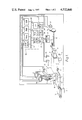
- FIG. 1 is a diagrammatic representation of the slicing machine and jump conveyor
- FIG. 2 is a flow diagram of the program controlling the end of the slicing operation.
- the basic mechanical construction of the slicing machine and jump conveyor is conventional and is typically like that known as a "Polyslicer” manufactured by Thurne Engineering Co. Ltd of Norwich, United Kingdom. It comprises a planetary blade 1, journalled in a counter-rotating hub 2. The blade 1 is driven by a motor 3 through pinion gears 4 and 5 and the hub 2 is driven by a motor 6. A block 7 of meat or a meat product is placed on a feed table (not shown) and driven towards the blade 1 by feeding head 8.
- the feeding head 8 is mounted on a bearer 9 which are carried on a pair of rails 10. The feeding head 8 and bearer 9 are moved backwards and forwards along the rails is by a lead screw 11 which is rotated by a motor 12.
- Slices 13 of meat or meat product cut from the block 7 fall onto a jump conveyor 14 located downstream of the blade and driven by a motor 15. Downstream from the jump conveyor 14 is a conveyor 16 passing over a weigh cell 17. Slices 13 are cut from the face of the block 7 of meat by the blade 1 at a uniform rate.
- the jump conveyor 14 moves forward continuously by the motor 15 at a first rate to provide a shingled group of slices as shown in FIG. 1 and then after completion of the number of slices to form that group the jump conveyor 14 is moved at a second, much faster rate by the motor 15, to provide a space between the last slice of one group and the first slice 13 of the next group.
- the groups of slices 13 are then fed from the jump conveyor 14 onto the conveyor 16 and as they pass over the weigh cell 17 their weight is monitored.
- the slicer Whilst the mechanical arrangement of the slicer is generally conventional, the slicer also includes a computer 18.
- the computer 18 may be based on type RT1-1260/1262 manufactured by Prolog Corporation of the U.S.A., for example.
- the computor 18 typically includes an event counter 19, a microprocessor 20, a programmable read only memory 21, a random access memory 22, parallel input/output ports 23, serial input/output ports 24, and digital to analogue convertor unit 25 all connected together by a bus 26.
- the computer 18 is also connected to operator control buttons 27, program control 28 and a motor controller 29.
- the motor controller 29 controls the operation of the motors 3, 6, 12 and 15 and these include encoders 30, 31, 32 and 33 respectively the outputs of which are fed into the computer.
- a cam 34 is mounted on the hub 2 and this cooperates with a proximity switch 35 to identify the angular position of the hub 2.
- the proximity switch 35 is triggered off both the leading and trailing end of the cam 34 and the computer 18 can naturally also calculate any intermediate angular position by timing between successive actuations of the proximity switch 35.
- FIG. 1 shows the encoders 30, 31, 32 and 33, and the proximity switch 35 directly linked to the event counter 19 for simplicity, in practice these are coupled through an opto-coupling unit 36 and the ports 23.
- the computer 18 is thus arranged to control the operation of the motors 3, 6, 12 and 15, and hence control the peripheral speed of the blade 1, the rate of rotation of the hub 2 and hence the rate at which the slices 13 are cut from the block 7, the rate of movement of the block 7 towards the blade 1 and hence the thickness of each slice 13, and also to control the operation of the jump conveyor 14 and hence the number of slices in each group. It also controls the time of operation of the motor 12 in accordance with the output from the proximity switch 35.
- the slicing machine also includes a physical abuttment 37 which enagages the bearer 9 and prevents the feeding head 8 coming into contact with the blade 1.
- the physical abuttment 37 is solely there to stop the feed head 8 engaging the blade 1 when all else has failed and, under normal circumstances the bearer 9 does not touch the abuttment 37.
- a position detector 38 is located beside the path of movement of the block of meat 7 and detects the presence of the feeding head 8 at a position a predetermined distance upstream from the blade 1.
- a further position detector 39 acts as an end stop detector and again detects the position of the feeding head 8 but detects the position of the feeding head 8 immediately before the bearer 9 engages the abuttment 37.
- the outputs from the detectors 38 and 39 are both fed via the opto-coupler unit 36 to the computer 18.
- FIG. 2 is a flow diagram of the program operated by the computer 18. Assuming at the moment that the block 7 of meat is being driven continuously towards the obiting blade 1 a slice 13 will cut from the face of the block 7 each time the blade 1 gyrates. An indication of this is given by the proximity switch 35 to the event counter 19 and the computer interrogates the event counter 19 to compare the current count of the number of slices that have been cut held by the event counter 19 with the required number of slices to be formed in each pack. If the number in the event counter 19 has not reached the preset number of slices required for each pack the slicing machine continues to operate.
- the computer 18 executes a jump cycle of the jump conveyor 14 by speeding up the motor 15.
- the computer 18 also determines whether the feed head 8 has passed the detector 38 and if it has not the event counter 19 is reset to zero and the process then is repeated for the next group of slices. This is the process that is performed throughout the majority of the length of the block of meat 7.
- a count down is started and this counts down from a preset value which, corresponds to the distance between the detector 38 and the blade 1 and each increment of the encoder 32 attached to the motor 12 driving the feed head 8 decrements the count so that each time a slice is cut from the face of the block of meat 7 the amount that the feed head 8 is moved forward is decremented from the initial count.
- the computer calculates the remaining length of block 7 to be cut from the current count and compares this with the thickness of the next slice that is to be cut.
- the computer 18 calculates to check that there is sufficient length of product remaining to enable a slice having the preset thickness to be cut. As soon as insufficient product 7 remains a stop feed head drive signal is produced. This is sent to the right hand side of the flow diagram in FIG. 2 and enters beneath the execute jump cycle instruction. When the stop feed head drive signal has been produced the computer operates the motor 12 in the opposite direction to return the feed head 8 to its starting point and, in due course, stops the operation of the jump conveyor 14.
- the end stop detector 39 is connected directly to the stop feed head drive instruction and overrides all other parts of the program so that if, for some reason, anything goes wrong and the feedhead 8 reaches the end stop detector 39 the cutting of that slice is immediately aborted.
- FIG. 2 illustrates that even if the stop feed head drive signal is given after only the first slice has been cut for a particular group, the number of slices in the event counter 19 are still compared with the preset number of slices required for each pack for each orbit of the blade 1 until the required number of slices have apparently been produced by the slicing machine. Only then and only after the jump cycle of the jump conveyor 14 has been executed does the stop feed head drive signal from the left hand side of FIG. 2 have any effect on the operation of the jump conveyor 14. Only when both a jump cycle has been executed and the stop feed head drive signal has been received does the jump conveyor stop. This ensures that the jump conveyor 14 always jumps with the leading slice of each group in the correct position and does not ever jump at any other time.
Abstract
Description
Claims (9)
Applications Claiming Priority (2)
| Application Number | Priority Date | Filing Date | Title |
|---|---|---|---|
| GB838314766A GB8314766D0 (en) | 1983-05-27 | 1983-05-27 | Slicing machine |
| GB8314766 | 1983-05-27 |
Publications (1)
| Publication Number | Publication Date |
|---|---|
| US4532840A true US4532840A (en) | 1985-08-06 |
Family
ID=10543500
Family Applications (1)
| Application Number | Title | Priority Date | Filing Date |
|---|---|---|---|
| US06/614,430 Expired - Fee Related US4532840A (en) | 1983-05-27 | 1984-05-29 | Slicing machine having means to determine if sufficient product remains to cut a whole slice |
Country Status (6)
| Country | Link |
|---|---|
| US (1) | US4532840A (en) |
| EP (1) | EP0127460B1 (en) |
| JP (1) | JPS59227398A (en) |
| CA (1) | CA1211687A (en) |
| DE (1) | DE3472912D1 (en) |
| GB (1) | GB8314766D0 (en) |
Cited By (36)
| Publication number | Priority date | Publication date | Assignee | Title |
|---|---|---|---|---|
| US4967652A (en) * | 1988-12-15 | 1990-11-06 | Oscar Mayer Foods Corporation | Pressing system for shaping bacon bellies and the like |
| US5064667A (en) * | 1988-12-15 | 1991-11-12 | Oscar Mayer Foods Corporation | Method for shaping bacon bellies |
| US5136906A (en) * | 1990-03-27 | 1992-08-11 | Thurne Engineering Co., Ltd. | Slicing machine |
| US5481466A (en) * | 1992-04-23 | 1996-01-02 | Townsend Engineering Company | Meat slicing machine and method of use thereof |
| US5628237A (en) * | 1994-10-11 | 1997-05-13 | Formax, Inc. | Slicing machine for two or more food loaves |
| US5724874A (en) * | 1994-10-11 | 1998-03-10 | Formax, Inc. | Method of manufacturing food loaf slice groups |
| WO1998031516A1 (en) * | 1997-01-17 | 1998-07-23 | Premark Feg L.L.C. | Slicer with staged dynamic braking system |
| US6508152B1 (en) | 1999-05-03 | 2003-01-21 | Rockford Manufacturing Group, Inc. | Clutchless wire cutting apparatus |
| US20030079589A1 (en) * | 2001-10-26 | 2003-05-01 | Mark Kovacs | Slicer carriage tracking arrangement and associated method of controlling food product carriage |
| US20030200848A1 (en) * | 2002-04-26 | 2003-10-30 | Fritz Kuchler | Slicing-machine drive |
| US20040134319A1 (en) * | 2003-01-10 | 2004-07-15 | Glenn Sandberg | System and method for optimizing slices from slicing apparatus |
| US20040253906A1 (en) * | 2001-02-12 | 2004-12-16 | William Willett | Compact motion mechanism for an animated doll |
| US20050199111A1 (en) * | 1999-04-20 | 2005-09-15 | Formax, Inc. | Automated product profiling apparatus and product slicing system using same |
| US20060288832A1 (en) * | 2003-04-09 | 2006-12-28 | Glenn Sandberg | System and apparatus for optimizing slices from slicing apparatus |
| US20070044622A1 (en) * | 2005-08-26 | 2007-03-01 | Zeeb Scott M | Product table lock for a food slicer |
| US20070044626A1 (en) * | 2005-08-26 | 2007-03-01 | Bondarowicz Frank A | Overmolded food product table support arm for a food slicer |
| US20070044628A1 (en) * | 2005-08-26 | 2007-03-01 | Rote Scott J | Rear pivot pusher for a food slicer with clearance position |
| US20070044605A1 (en) * | 2005-08-26 | 2007-03-01 | Zeeb Scott M | Gage plate alignment mechanism and method for a food slicer |
| US20070044612A1 (en) * | 2005-08-26 | 2007-03-01 | Somal Hardev S | Gage plate adjustment mechanism for a food slicer |
| US20070049181A1 (en) * | 2005-08-26 | 2007-03-01 | Zeeb Scott M | Sharpener carried by the product table of a food slicer |
| US20070044621A1 (en) * | 2005-08-26 | 2007-03-01 | Rote Scott J | Top mounted operator interface for a food slicer |
| US20070044625A1 (en) * | 2005-08-26 | 2007-03-01 | Rote Scott J | Product table for a food slicer with hollow peripheral reinforcements |
| US20070044627A1 (en) * | 2005-08-26 | 2007-03-01 | Clem Todd L | Speed and stroke control method and apparatus for a product table of a food slicer |
| US20070180971A1 (en) * | 2006-02-07 | 2007-08-09 | Zeeb Scott M | Product fence for a food slicer |
| US20070215248A1 (en) * | 2006-03-17 | 2007-09-20 | Benoit Carpentier | Closed-loop cutting system |
| GB2446566A (en) * | 2007-02-15 | 2008-08-20 | Aew Delford Systems Ltd | Control of Food Slicing Machines |
| US20090120256A1 (en) * | 2007-10-22 | 2009-05-14 | Pasek James E | Food Article Feed Apparatus for a Food Article Slicing Machine |
| US20100064872A1 (en) * | 2008-09-12 | 2010-03-18 | Anatoly Gosis | Product fence for food slicer |
| US20100089254A1 (en) * | 2008-10-14 | 2010-04-15 | Anatoly Gosis | Food slicer and associated food product pusher |
| US7971510B2 (en) * | 2001-09-05 | 2011-07-05 | Weber Maschinenbau Gmbh Breidenbach | Method for setting a cutting gap |
| US20120089244A1 (en) * | 2010-10-06 | 2012-04-12 | Weber Maschinenbau Gmbh Breidenbach | Method for slicing foodstuffs |
| US20150053057A1 (en) * | 2013-08-22 | 2015-02-26 | Weber Maschinenbau Gmbh Breidenbach | Apparatus for slicing food products and method of providing intermediate sheets |
| US9285213B2 (en) | 2009-10-27 | 2016-03-15 | Formax, Inc. | Automated product profiling apparatus and product slicing system using the same |
| US20190152084A1 (en) * | 2016-02-01 | 2019-05-23 | Textor Maschinenbau GmbH | Cutting food products |
| WO2020172051A1 (en) * | 2019-02-22 | 2020-08-27 | Provisur Technologies, Inc. | Pivoting blade assembly for high-speed food slicing machine |
| US20220117244A1 (en) * | 2019-02-12 | 2022-04-21 | Marel A/S | Controlling angular speed of eccentric movement of circular blade |
Families Citing this family (2)
| Publication number | Priority date | Publication date | Assignee | Title |
|---|---|---|---|---|
| JPH0256595U (en) * | 1988-10-13 | 1990-04-24 | ||
| GB8911522D0 (en) * | 1989-05-19 | 1989-07-05 | Thurne Eng Co Ltd | A product slicing system |
Citations (3)
| Publication number | Priority date | Publication date | Assignee | Title |
|---|---|---|---|---|
| US4309927A (en) * | 1979-12-05 | 1982-01-12 | Cashin Systems Corporation | Continuous cold cut slicing machine |
| US4344341A (en) * | 1980-09-04 | 1982-08-17 | Lotz Walter E | Slicing apparatus |
| US4457194A (en) * | 1981-09-28 | 1984-07-03 | Oscar Mayer Foods Corporation | Slicing method and apparatus |
Family Cites Families (5)
| Publication number | Priority date | Publication date | Assignee | Title |
|---|---|---|---|---|
| US3835742A (en) * | 1972-08-22 | 1974-09-17 | Cashin Systems Corp | Apparatus for stacking and weighing sliced food products |
| AT326514B (en) * | 1972-08-22 | 1975-12-10 | Kuchler Fritz | FILING DEVICE FOR A SLICING MACHINE |
| GB1502099A (en) * | 1975-05-02 | 1978-02-22 | Berkel & Parnall Ltd | Food slicing apparatus |
| US4226147A (en) * | 1978-10-27 | 1980-10-07 | Chemetron Corporation | Slice control circuit for a slicing machine |
| DE3119102A1 (en) * | 1980-05-16 | 1982-05-13 | Maatschappij van Berkel's, Patent N.V., Rotterdam | Slicing machine for foodstuffs |
-
1983
- 1983-05-27 GB GB838314766A patent/GB8314766D0/en active Pending
-
1984
- 1984-05-25 EP EP84303547A patent/EP0127460B1/en not_active Expired
- 1984-05-25 DE DE8484303547T patent/DE3472912D1/en not_active Expired
- 1984-05-28 CA CA000455278A patent/CA1211687A/en not_active Expired
- 1984-05-28 JP JP59108266A patent/JPS59227398A/en active Pending
- 1984-05-29 US US06/614,430 patent/US4532840A/en not_active Expired - Fee Related
Patent Citations (3)
| Publication number | Priority date | Publication date | Assignee | Title |
|---|---|---|---|---|
| US4309927A (en) * | 1979-12-05 | 1982-01-12 | Cashin Systems Corporation | Continuous cold cut slicing machine |
| US4344341A (en) * | 1980-09-04 | 1982-08-17 | Lotz Walter E | Slicing apparatus |
| US4457194A (en) * | 1981-09-28 | 1984-07-03 | Oscar Mayer Foods Corporation | Slicing method and apparatus |
Cited By (70)
| Publication number | Priority date | Publication date | Assignee | Title |
|---|---|---|---|---|
| US4967652A (en) * | 1988-12-15 | 1990-11-06 | Oscar Mayer Foods Corporation | Pressing system for shaping bacon bellies and the like |
| US5064667A (en) * | 1988-12-15 | 1991-11-12 | Oscar Mayer Foods Corporation | Method for shaping bacon bellies |
| US5136906A (en) * | 1990-03-27 | 1992-08-11 | Thurne Engineering Co., Ltd. | Slicing machine |
| US5481466A (en) * | 1992-04-23 | 1996-01-02 | Townsend Engineering Company | Meat slicing machine and method of use thereof |
| US5628237A (en) * | 1994-10-11 | 1997-05-13 | Formax, Inc. | Slicing machine for two or more food loaves |
| US5724874A (en) * | 1994-10-11 | 1998-03-10 | Formax, Inc. | Method of manufacturing food loaf slice groups |
| WO1998031516A1 (en) * | 1997-01-17 | 1998-07-23 | Premark Feg L.L.C. | Slicer with staged dynamic braking system |
| US5862730A (en) * | 1997-01-17 | 1999-01-26 | Premark Feg L.L.C. | Slicer with staged dynamic braking system |
| US6092448A (en) * | 1997-01-17 | 2000-07-25 | Premark Feg L.L.C. | Slicer with staged dynamic braking system |
| US7450247B2 (en) | 1999-04-20 | 2008-11-11 | Fermax, Inc. | Automated product profiling apparatus and product slicing system using same |
| US20090064833A1 (en) * | 1999-04-20 | 2009-03-12 | Glenn Sandberg | Automated Product Profiling Apparatus and Product Slicing System Using Same |
| US7623249B2 (en) | 1999-04-20 | 2009-11-24 | Formax, Inc. | Automated product profiling apparatus and product slicing system using same |
| US20050199111A1 (en) * | 1999-04-20 | 2005-09-15 | Formax, Inc. | Automated product profiling apparatus and product slicing system using same |
| US6769336B2 (en) | 1999-05-03 | 2004-08-03 | Rockford Manufacturing Group, Inc. | Clutchless wire cutting apparatus |
| US6508152B1 (en) | 1999-05-03 | 2003-01-21 | Rockford Manufacturing Group, Inc. | Clutchless wire cutting apparatus |
| US6708591B1 (en) * | 1999-05-03 | 2004-03-23 | Rockford Manufacturing Group, Inc. | Clutchless wire cutting apparatus |
| US6988928B2 (en) | 2001-02-12 | 2006-01-24 | Mattel, Inc. | Compact motion mechanism for an animated doll |
| US20040253906A1 (en) * | 2001-02-12 | 2004-12-16 | William Willett | Compact motion mechanism for an animated doll |
| US7971510B2 (en) * | 2001-09-05 | 2011-07-05 | Weber Maschinenbau Gmbh Breidenbach | Method for setting a cutting gap |
| US7398718B2 (en) | 2001-10-26 | 2008-07-15 | Premark Feg L.L.C. | Method for controlling a slicing operation |
| US20050132854A1 (en) * | 2001-10-26 | 2005-06-23 | Mark Kovacs | Slicer carriage tracking arrangement and associated method of controlling food product carriage |
| US20030079589A1 (en) * | 2001-10-26 | 2003-05-01 | Mark Kovacs | Slicer carriage tracking arrangement and associated method of controlling food product carriage |
| US6845697B2 (en) | 2001-10-26 | 2005-01-25 | Premark Feg L.L.C. | Slicer carriage tracking arrangement |
| US6931973B2 (en) * | 2002-04-26 | 2005-08-23 | Fritz Kuchler | Slicing-machine drive |
| US20030200848A1 (en) * | 2002-04-26 | 2003-10-30 | Fritz Kuchler | Slicing-machine drive |
| US20040134319A1 (en) * | 2003-01-10 | 2004-07-15 | Glenn Sandberg | System and method for optimizing slices from slicing apparatus |
| US7055419B2 (en) | 2003-01-10 | 2006-06-06 | Formax, Inc. | System and method for optimizing slices from slicing apparatus |
| US20060288832A1 (en) * | 2003-04-09 | 2006-12-28 | Glenn Sandberg | System and apparatus for optimizing slices from slicing apparatus |
| US7832317B2 (en) | 2005-08-26 | 2010-11-16 | Premark Feg L.L.C. | Gage plate alignment mechanism and method for a food slicer |
| US20070044626A1 (en) * | 2005-08-26 | 2007-03-01 | Bondarowicz Frank A | Overmolded food product table support arm for a food slicer |
| US20070044625A1 (en) * | 2005-08-26 | 2007-03-01 | Rote Scott J | Product table for a food slicer with hollow peripheral reinforcements |
| US20070044627A1 (en) * | 2005-08-26 | 2007-03-01 | Clem Todd L | Speed and stroke control method and apparatus for a product table of a food slicer |
| US8043142B2 (en) | 2005-08-26 | 2011-10-25 | Premark Feg L.L.C. | Sharpener carried by the product table of a food slicer |
| US20070044628A1 (en) * | 2005-08-26 | 2007-03-01 | Rote Scott J | Rear pivot pusher for a food slicer with clearance position |
| US20070049181A1 (en) * | 2005-08-26 | 2007-03-01 | Zeeb Scott M | Sharpener carried by the product table of a food slicer |
| US7637191B2 (en) | 2005-08-26 | 2009-12-29 | Premark Feg L.L.C. | Product table lock for a food slicer |
| US20070044612A1 (en) * | 2005-08-26 | 2007-03-01 | Somal Hardev S | Gage plate adjustment mechanism for a food slicer |
| US20070044622A1 (en) * | 2005-08-26 | 2007-03-01 | Zeeb Scott M | Product table lock for a food slicer |
| US7549363B2 (en) | 2005-08-26 | 2009-06-23 | Premark Feg L.L.C. | Product table for a food slicer with hollow peripheral reinforcements |
| US20070044605A1 (en) * | 2005-08-26 | 2007-03-01 | Zeeb Scott M | Gage plate alignment mechanism and method for a food slicer |
| US20070044621A1 (en) * | 2005-08-26 | 2007-03-01 | Rote Scott J | Top mounted operator interface for a food slicer |
| US7464632B2 (en) | 2006-02-07 | 2008-12-16 | Premark Feg L.L.C. | Product fence for a food slicer |
| US20070180971A1 (en) * | 2006-02-07 | 2007-08-09 | Zeeb Scott M | Product fence for a food slicer |
| US20070215248A1 (en) * | 2006-03-17 | 2007-09-20 | Benoit Carpentier | Closed-loop cutting system |
| US8117952B2 (en) * | 2006-03-17 | 2012-02-21 | Benoit Carpentier | Closed-loop cutting system |
| GB2446566B (en) * | 2007-02-15 | 2009-01-07 | Aew Delford Systems Ltd | Control of food slicing machines |
| GB2446566A (en) * | 2007-02-15 | 2008-08-20 | Aew Delford Systems Ltd | Control of Food Slicing Machines |
| US8850938B2 (en) * | 2007-10-22 | 2014-10-07 | Formax, Inc. | Maintenance and safety system for a food article slicing machine |
| US8616103B2 (en) | 2007-10-22 | 2013-12-31 | Formax, Inc | Knife blade retraction mechanism for a food article slicing machine |
| US8978529B2 (en) | 2007-10-22 | 2015-03-17 | Formax, Inc. | Food article feed apparatus for a food article slicing machine |
| US20090120256A1 (en) * | 2007-10-22 | 2009-05-14 | Pasek James E | Food Article Feed Apparatus for a Food Article Slicing Machine |
| US20090188358A1 (en) * | 2007-10-22 | 2009-07-30 | David Hansen | Output Conveyor for a Food Article Slicing Machine |
| US20090173196A1 (en) * | 2007-10-22 | 2009-07-09 | Lindee Scott A | Maintenance and Safety System for a Food Article Slicing Machine |
| US20090151527A1 (en) * | 2007-10-22 | 2009-06-18 | Lindee Scott A | Knife Blade Retraction Mechanism for a Food Article Slicing Machine |
| US20090148577A1 (en) * | 2007-10-22 | 2009-06-11 | Glenn Sandberg | Food Article End Detection System for a Food Article Slicing Machine |
| US20090188357A1 (en) * | 2007-10-22 | 2009-07-30 | Lindee Scott A | Information Carrier System for a Food Article Slicing Machine |
| US8336434B2 (en) * | 2007-10-22 | 2012-12-25 | Formax, Inc. | Food article end detection system for a food article slicing machine |
| US8549966B2 (en) | 2007-10-22 | 2013-10-08 | Formax, Inc. | Output conveyor for a food article slicing machine |
| US20100064872A1 (en) * | 2008-09-12 | 2010-03-18 | Anatoly Gosis | Product fence for food slicer |
| US20100089254A1 (en) * | 2008-10-14 | 2010-04-15 | Anatoly Gosis | Food slicer and associated food product pusher |
| US9285213B2 (en) | 2009-10-27 | 2016-03-15 | Formax, Inc. | Automated product profiling apparatus and product slicing system using the same |
| US9888696B2 (en) | 2009-10-27 | 2018-02-13 | Formax, Inc. | Automated product profiling apparatus and product slicing system using the same |
| US20120089244A1 (en) * | 2010-10-06 | 2012-04-12 | Weber Maschinenbau Gmbh Breidenbach | Method for slicing foodstuffs |
| US8892239B2 (en) * | 2010-10-06 | 2014-11-18 | Weber Maschinenbau Gmbh Breidenbach | Method for slicing foodstuffs |
| US20150053057A1 (en) * | 2013-08-22 | 2015-02-26 | Weber Maschinenbau Gmbh Breidenbach | Apparatus for slicing food products and method of providing intermediate sheets |
| US9981400B2 (en) * | 2013-08-22 | 2018-05-29 | Weber Maschinenbau Gmbh Breidenbach | Apparatus for slicing food products and method of providing intermediate sheets |
| US20190152084A1 (en) * | 2016-02-01 | 2019-05-23 | Textor Maschinenbau GmbH | Cutting food products |
| US20220117244A1 (en) * | 2019-02-12 | 2022-04-21 | Marel A/S | Controlling angular speed of eccentric movement of circular blade |
| WO2020172051A1 (en) * | 2019-02-22 | 2020-08-27 | Provisur Technologies, Inc. | Pivoting blade assembly for high-speed food slicing machine |
| US11845195B2 (en) | 2019-02-22 | 2023-12-19 | Provisur Technologies, Inc. | Pivoting blade assembly for high-speed food slicing machine |
Also Published As
| Publication number | Publication date |
|---|---|
| GB8314766D0 (en) | 1983-07-06 |
| EP0127460B1 (en) | 1988-07-27 |
| EP0127460A1 (en) | 1984-12-05 |
| DE3472912D1 (en) | 1988-09-01 |
| CA1211687A (en) | 1986-09-23 |
| JPS59227398A (en) | 1984-12-20 |
Similar Documents
| Publication | Publication Date | Title |
|---|---|---|
| US4532840A (en) | Slicing machine having means to determine if sufficient product remains to cut a whole slice | |
| EP0127462B1 (en) | A slicing machine | |
| US5724874A (en) | Method of manufacturing food loaf slice groups | |
| US5241885A (en) | Slicing machine with accident protection | |
| CA2154337C (en) | Food loaf slicing machines | |
| US5566600A (en) | Conveyor/classifier system for versatile hi-speed food loaf slicing machine | |
| US4216689A (en) | Weight controlled bread loaf slicer | |
| US4548108A (en) | Slicing machine | |
| US4552048A (en) | Automatic trimming feature for a slicing machine | |
| US4226147A (en) | Slice control circuit for a slicing machine | |
| JPH0373294A (en) | Complex device of jump conveyor and slicing machine | |
| EP0398602B1 (en) | A product slicing system | |
| US3827319A (en) | Weight controlled slicing system | |
| US3543624A (en) | Feed device for flying shear | |
| US4434692A (en) | Grid-type bread-slicing machine | |
| US20020050198A1 (en) | Slicing machine with high-accuracy slice thickness | |
| US4531436A (en) | Slicing machine having interrupt means | |
| US3667520A (en) | Weight controlled slicing system including gross error detecting means | |
| CN110625661B (en) | Production line for quantitative segmentation and control method | |
| CN108326200A (en) | A kind of control mode of high speed bar straightener sizing accuracy | |
| US10850419B2 (en) | Method for operating a slicing machine, and slicing machine for spaced storage of slices of product | |
| US4344341A (en) | Slicing apparatus | |
| CN110605744B (en) | Production line control method | |
| EP3962704B1 (en) | Feeding of products in food slicers |
Legal Events
| Date | Code | Title | Description |
|---|---|---|---|
| AS | Assignment |
Owner name: THURNE ENGINEERING COMPANY LIMITED, DELTA CLOSE, S Free format text: ASSIGNMENT OF ASSIGNORS INTEREST.;ASSIGNOR:ANTONISSEN, PETER;REEL/FRAME:004266/0210 Effective date: 19840514 Owner name: THURNE ENGINEERING COMPANY LIMITED,ENGLAND Free format text: ASSIGNMENT OF ASSIGNORS INTEREST;ASSIGNOR:ANTONISSEN, PETER;REEL/FRAME:004266/0210 Effective date: 19840514 |
|
| FEPP | Fee payment procedure |
Free format text: PAYOR NUMBER ASSIGNED (ORIGINAL EVENT CODE: ASPN); ENTITY STATUS OF PATENT OWNER: LARGE ENTITY |
|
| FPAY | Fee payment |
Year of fee payment: 4 |
|
| FPAY | Fee payment |
Year of fee payment: 8 |
|
| REMI | Maintenance fee reminder mailed | ||
| LAPS | Lapse for failure to pay maintenance fees | ||
| FP | Lapsed due to failure to pay maintenance fee |
Effective date: 19970806 |
|
| STCH | Information on status: patent discontinuation |
Free format text: PATENT EXPIRED DUE TO NONPAYMENT OF MAINTENANCE FEES UNDER 37 CFR 1.362 |