US4532757A - Robotic fruit harvester - Google Patents
Robotic fruit harvester Download PDFInfo
- Publication number
- US4532757A US4532757A US06/537,833 US53783383A US4532757A US 4532757 A US4532757 A US 4532757A US 53783383 A US53783383 A US 53783383A US 4532757 A US4532757 A US 4532757A
- Authority
- US
- United States
- Prior art keywords
- fruit
- arm
- picking
- harvester
- aperture
- Prior art date
- Legal status (The legal status is an assumption and is not a legal conclusion. Google has not performed a legal analysis and makes no representation as to the accuracy of the status listed.)
- Expired - Fee Related
Links
Images


Classifications
-
- B—PERFORMING OPERATIONS; TRANSPORTING
- B25—HAND TOOLS; PORTABLE POWER-DRIVEN TOOLS; MANIPULATORS
- B25J—MANIPULATORS; CHAMBERS PROVIDED WITH MANIPULATION DEVICES
- B25J9/00—Programme-controlled manipulators
- B25J9/02—Programme-controlled manipulators characterised by movement of the arms, e.g. cartesian coordinate type
- B25J9/04—Programme-controlled manipulators characterised by movement of the arms, e.g. cartesian coordinate type by rotating at least one arm, excluding the head movement itself, e.g. cylindrical coordinate type or polar coordinate type
-
- A—HUMAN NECESSITIES
- A01—AGRICULTURE; FORESTRY; ANIMAL HUSBANDRY; HUNTING; TRAPPING; FISHING
- A01D—HARVESTING; MOWING
- A01D46/00—Picking of fruits, vegetables, hops, or the like; Devices for shaking trees or shrubs
- A01D46/24—Devices for picking apples or like fruit
-
- A—HUMAN NECESSITIES
- A01—AGRICULTURE; FORESTRY; ANIMAL HUSBANDRY; HUNTING; TRAPPING; FISHING
- A01D—HARVESTING; MOWING
- A01D46/00—Picking of fruits, vegetables, hops, or the like; Devices for shaking trees or shrubs
- A01D46/30—Robotic devices for individually picking crops
-
- B—PERFORMING OPERATIONS; TRANSPORTING
- B25—HAND TOOLS; PORTABLE POWER-DRIVEN TOOLS; MANIPULATORS
- B25J—MANIPULATORS; CHAMBERS PROVIDED WITH MANIPULATION DEVICES
- B25J19/00—Accessories fitted to manipulators, e.g. for monitoring, for viewing; Safety devices combined with or specially adapted for use in connection with manipulators
- B25J19/02—Sensing devices
- B25J19/021—Optical sensing devices
-
- Y—GENERAL TAGGING OF NEW TECHNOLOGICAL DEVELOPMENTS; GENERAL TAGGING OF CROSS-SECTIONAL TECHNOLOGIES SPANNING OVER SEVERAL SECTIONS OF THE IPC; TECHNICAL SUBJECTS COVERED BY FORMER USPC CROSS-REFERENCE ART COLLECTIONS [XRACs] AND DIGESTS
- Y10—TECHNICAL SUBJECTS COVERED BY FORMER USPC
- Y10S—TECHNICAL SUBJECTS COVERED BY FORMER USPC CROSS-REFERENCE ART COLLECTIONS [XRACs] AND DIGESTS
- Y10S56/00—Harvesters
- Y10S56/15—Condition responsive
Definitions
- the present invention relates to methods and apparatus for mechanical harvesting of fruit and the like, and more particularly to a robotic fruit harvester utilizing optical location of pickable fruit.
- My invention is particularly suitable for harvesting of citrus fruit.
- a successful system must provide the harvesting functions of selection, detachment, collection, and transport.
- the harvester must discriminate between ripe, mature fruit and immature fruit, leaves, branches, and the like. After the mature fruit is identified, it must be detached from its physical connection to the tree. Once the fruit is detached, it must be collected from that point and placed in a container for transportation from the grove to the packing house.
- Mass harvesting does not discriminate individual fruit and has generally been attempted by the use of limb and tree shakers, tines which project into the trees and oscillate or rotate, or by use of air blasts.
- the fruit that is detached generally is permitted to fall to the ground or to a canopy under the tree for collection. This often results in fruit damage due to the fruit striking branches and tearing of the abscission layer or the peel, resulting in plugged fruit.
- each fruit is treated as an entity and means are provided for selecting and detaching each fruit.
- a number of devices have been proposed and tried for this purpose.
- U.S. Pat. No. 3,925,973 uses a hollow cylindrical housing having a spiral auger which traps the fruit, severs it, and carries it back to a discharge outlet.
- a typical vacuum operative fruit harvester is taught in U.S. Pat. No. 4,388,798 in which a picker stands on the ground and extends a conduit into the tree. Suction pulls the fruit into the conduit which includes means for severing the fruit from the stem.
- French patent 7,528,286 utilizes a manually controlled head having a suction source with a small circular saw for cutting the stem.
- a mechanical fruit harvester preferably will be applicable to a large range of tree and fruit sizes.
- Fruit diameters for oranges may range from five to ten centimeters, and the harvester must be able to accommodate this range.
- the location of the fruit on the trees is an important consideration for a mechanical harvester.
- One study* has shown that trees up to 35 years old, having average heights not exceeding five meters, have 90% of the fruit at a canopy depth of 0-1 meter. Additionally, 90% of the fruit is found in the lower four meters of the tree. If a tree is divided into zones of about 3/10 meter square, it is found that 68% of the zones contain one fruit; 18%, 2 fruit; 8%, 3 fruit; and 6%, 4-7 fruit.
- a harvesting method and apparatus would be usable on any existing grove.
- the most efficient and effective use of mechanical harvesting methods will probably require matching of the grove configuration to the equipment.
- proper hedging of the trees to concentrate fruit in zones where the majority of the fruit will be picked is an important consideration.
- My invention is a method and apparatus for individual fruit harvesting which includes the functions of selection, detachment, collection, and transport.
- the system although particularly adaptable for citrus, may be used with any type of fruit having sufficient color or reflectance contrast with its surroundings.
- the method of harvesting in its most elemental form includes the steps of: locating and mapping fruit on the tree; positioning a picking arm at each mapped location; detaching the fruit from its stem; and collecting the fruit for transport.
- a basic element of the element of the apparatus of my invention is a module which will contain the equipment for locating and mapping the fruit, and the picking arm positioning and operating apparatus.
- several modules are mounted on a flatbed trailer which is towed through a grove to be picked.
- the modules are extended and retracted vertically adjacent the face of a tree to be picked.
- several modules for example, three, may be disposed side by side and operated simultaneously.
- a module having a width of about three meters is eminently suitable with three such modules having the capability of servicing a tree having a face width of about nine meters without movement of the trailer.
- a module may have any desired size and aspect ratio, I prefer an approximately square module of about three meters on the side and about two meters deep.
- the module may be in the form of a box having one side open to form an approximately square aperture.
- Contained within the module are three basic elements: a floodlighting system; an optical global sensor array which is disposable on the geometric center line of the aperture; and an extensible picking arm having a picking element at its distal end.
- An elevation and traverse mechanism is provided in the module which, during a global optical detection and mapping phase, places the optical global sensor array at the center of the aperture producing what may be termed a bore site optical axis normal to the aperture face. After the detection and mapping phase, the mechanism moves the optical sensor array from the bore site location and moves the proximal end of the picking arm to the bore site location during a picking phase.
- the flatbed trailer may advantageously include a light beam locating system to assist the operator in positioning the trailer and modules opposite a tree face for picking.
- the trailer is moved until the location system indicates that the center line of the trailer is aligned with the trunk of a tree to be picked.
- the modules will face the tree with the open apertures adjacent the tree face.
- Each module is mounted on an elevating mechanism attached to the trailer bed.
- the elevating mechanism has the capability of translating the module in a vertical direction to a selected maximum height. Generally, after the equipment is in position facing a tree, a module is extended vertically to the top of the tree at which point the open aperture defines a picking zone.
- the optical global sensor array is aligned with the optical axis.
- the sensor array is in effect a camera having a resolution of, for example, 256 ⁇ 256 pixels.
- the floodlights which may be disposed around the periphery of the aperture and focused over the aperture area, are flashed to produce an intense wide spectrum illumination of the foliage and fruit.
- the sensor array threshold is set to minimize effective ambient light, a very high contrast illuminated scene is presented and interference from sunlight is eliminated.
- the reflectance studies have also shown that ripe citrus fruit of a normal orange or yellow color will have a high reflectance in the 600 nm range, while green or immature fruit may have 1/4 or less reflectance. For this reason, I prefer to utilize optical filters for the sensor array passing light in the region between 600-700 nm. Therefore, the camera sensor device will produce a map of the picking zone defined by aperture having spots of high intensity light representative of fruit and areas of low level intensity representative of leaves and background.
- the sensor is connected to a computer system via processing circuits which may be utilized to improve the discrimination between fruit and background. Additionally, the use of changeable sensor array filters combined with electronic processing may provide improved discrimination as discussed more fully below. The processing assists to identify a small center for each detected fruit, thereby resolving clusters of fruit into individual fruits.
- the computer identifies the X-Y coordinate within the aperture and picking zone of each of the identified fruits, storing this information for the picking operation. As may be understood, this process is completed almost instantaneously upon positioning of the aperture.
- the optical sensor camera is moved from the bore site point and the picking arm moved such that its proximal end is in the position formerly occupied by the camera.
- the arm has three degrees of freedom about the proximal point of the arm controllable by the arm control mechanism with signals from the computer.
- the picking arm consists generally of several telescoping joints with a small drive motor disposed at each joint for extending and retracting the respective arm sections. When fully retracted the arm will be contained within the module enclosure.
- the arm is capable of extending to a selected depth depending upon the size of the trees to be harvested.
- a fruit severance head is disposed at the outer end of the arm and is used to grasp and separate the fruit from its stem as will be described hereinafter.
- the computer controls the arm to extend along what may be termed a ray line from the aperture geometric center to the X-Y coordinate of the first fruit location stored in memory. As will be recognized, this ray line would be coincident with the reflected light ray from that fruit to the camera during the mapping operation.
- the arm is then extended along this ray line toward the X-Y fruit location.
- a secondary sensing system is provided in the picking arm.
- a light source disposed within the outer section of the picking arm projects a focused beam, through a suitable lens system, which will strike a fruit lying along the axis of the arm and will be reflected back into a four quadrant light sensor.
- the fruit severance head including the light source and quadrant sensor, are oscillated or nutated by a small drive unit also disposed at the outer arm end.
- a small drive unit also disposed at the outer arm end.
- the reflected light from a fruit will produce a rotating light beam falling on the quad sensors.
- These sensors are connected in a conventional servo mechanism which controls the arm positioning such that it places the arm axis coincident with the center of the reflecting surface, thereby aligning the picking arm with a fruit.
- the oscillating severance head will move relatively slowly toward the fruit.
- the fruit severance head includes a set of four tactile proximity sensors and a set of four grippers.
- the grippers are symmetrically disposed around the end of the severance head which has a diameter large enough to accept the largest fruit to be picked.
- Tactile sensors are provided rearward from the grippers with the result that the arm moves forward with the grippers surrounding the fruit until the fruit makes contact with a tactile sensor. This contact closes a circuit which causes the grippers to close onto the fruit.
- I also provide an obstruction sensor somewhat further forward and associated with the grippers in case the grippers should contact a limb or other obstruction prior to reaching a fruit.
- a signal is presented to the computer causing the arm to move more slowly and to attempt to dislodge the obstruction.
- the forward arm drive motor current is monitored to sense an increase in load if, as would occur, the obstruction were solid or immovable. In such case, the arm would immediately retract to prevent damage to the severance head.
- the computer instructs the head to perform two picking motions: one motion to nod or pivot the head to place a strain on the stem; and then to impart a twisting motion thereto to separate the fruit from its stem. As may be noted, this movement approximates that of the human picker.
- a field box or the like may be towed or moved adjacent the module trailer which, when full, would be used for transporting the picked fruit to the storage point.
- the trailer includes a series of gutters which feed into a conveyor device such as an auger feed for carrying the fruit into the field box.
- Each module is equipped with a gutter-like device along the lower edge of the aperture and a set of chutes connecting the aperture gutter to the trailer gutters.
- the chutes comprise several jointed sections which permit extension and retraction of the chutes as the module is raised and lowered.
- the joints serve to slow down the descent of fruit through the chutes to minimize bruising or other damage.
- the fruit is carried from the severance head to the aperture gutter by means of an extensible and articulated collection arm attached at its proximal end and at the proximal end of the picking arm.
- Small individual motors drive the collection arm sections and controlled by the computer in parallel with the control of the picking arm.
- a collection cup is disposed which will hold several fruit.
- the computer controls the positioning of this cup to always be slightly to the rear of the severance head and below the head.
- the arm retracts quickly to a position placing the severance head immediately above the collection cup. At that point, the grippers are opened, permitting the fruit to drop into the cup.
- the severance head and picker arm are in condition to sense whether additional fruit is available on the particular picker arm axis. If so, the nutation of the severance head is started and a forward movement of the arm is initiated to determine if any additional fruit is within range. If at full extension no more fruit is found, the arm retracts into the module and the arm is moved to the next X-Y coordinate from the stored mapping system. As the arm retracts into the module, it is followed by the collection arm and cup.
- the computer instructs the control motor to dump the contents of the cup into the gutter.
- the gutter may be arranged at an angle for gravity feed to the chutes or, alternatively, a wire auger may be provided in the gutter for moving the fruit to the chute. As will now be evident, the fruit will move down the chute and into the field box.
- the arm After the arm has moved to each X-Y coordinate stored in the mapping memory and performed its picking function, the arm is fully retracted into the module and the module is moved downward until the aperture is facing the next lower picking zone.
- the picking zones will be selected to be contiguous which produces some overlap due to the fact that the arm will extend both above and below the upper and lower aperture boundaries.
- the arms will provide some lateral overlap. This assists in assuring that the maximum possible percentage of fruit will be located and picked.
- a module is moved to the top position at which point it has the capability of rotating 180° .
- the layout of the grove, the spacing between trees, and the hedging performed provides a face to face spacing of about two meters, the faces of opposing trees can therefore be picked with my modules without moving of the trailer.
- plantings and hedgings have not been planned for mechanized picking, it may be necessary to reposition the trailer to pick the opposite tree faces.
- FIG. 1 shows a perspective view of a typical module in accordance with my invention, having the picking arm in position for locating and severing fruit;
- FIG. 2 is a simplified side view of a trailer having mountings for three of the modules of FIG. 1;
- FIG. 3 is an end view of the trailer of FIG. 2;
- FIG. 4 is a partial cut-away view of the module base and the supporting module columns
- FIG. 5 is a detailed view of the outriggers used with the trailer of FIG. 2 and 3;
- FIG. 6 is a perspective view of the severance head attached to the distal end of the picker arm
- FIG. 7 is a cross sectional view of the forward portion of the severance head of FIG. 6;
- FIG. 8 is an outline view of the quad detector shown in the cross sectional view of FIG. 7;
- FIG. 9 is a schematic diagram of the quad detector of FIG. 8;
- FIG. 10 is a partial and exploded view of one of the grippers of the severance head, showing the manner in which the gripper is operated;
- FIG. 11 is a cross sectional view of the nutation control seen in FIG. 6;
- FIG. 12 is a perspective view of the yoke assemblies used in the nutation control of FIG. 11;
- FIG. 13 is a plot of the reflectance of various oranges and leaves, and a plot of the ratio of reflected light from fruit and leaves;
- FIG. 14 is a simplified block diagram of the electronic control system of my invention, including the location mapping system;
- FIG. 15 is a more detailed block diagram of the brightness discriminator of FIG. 14;
- FIG. 16 is a flow diagram showing the operations on the data stored in the third memory of FIG. 15 to discriminate between fruit and background;
- FIG. 17 is a simplified block diagram of the power sources for my system.
- FIG. 18 is a schematic of a module disposed at a fruit-bearing tree.
- My invention is a complete harvesting system for fruits and is applicable to many types of fruits. However, I will describe my system as applied in particular to citrus fruits. The system locates the fruit on the trees, picks the fruit, collects the fruit, and delivers the fruit to a field box for transport.
- a basic unit of my invention is a picking module 10 shown in somewhat simplified form in FIG. 1.
- a housing 12 is provided which may be formed from aluminum or other metal. Although housing 12 may be of any desired size, I prefer a housing having the dimension A of 2-1/2 to 3 meters, dimension B from 2-1/2 to 3 meters, and dimension C about 2 meters. Housing 12 is enclosed on five sides, having one side open forming an aperture 11. As will be discussed more fully below, aperture 11 defines a picking zone.
- Housing 12 is supported on a base plate 42 and is pivoted at the center of its bottom side 29 to base 42, although the pivot 43 cannot be seen in FIG. 1.
- housing 12 is free to rotate on base 42 and is adapted to be used in two fixed positions; one, as shown in FIG. 1, and a second position in which housing 12 is rotated 180° such that aperture 11 faces in the opposite direction.
- a picker arm assembly shown generally at 21 and an optical global sensor array or camera 16 supported by bracket 17.
- Picking arm assembly 21 is supported by a translational mechanism including vertical translation means 25 and horizontal translation means 27.
- the translational mechanism system is supported on a scissors mechanism 20 which may be motor driven and will serve to maintain the picking arm assembly 21 and camera 16 in either of two positions. In a first position, scissors mechanism 20 is completely retracted such that the picker arm assembly 21 is disposed at the bottom of housing 12 and the optical axis of camera 16 is at the geometric center of housing 12 and aligned with the aperture center line shown. In the second position, illustrated in FIG. 1, scissors mechanism has been extended upward such that camera 16 is moved away from the geometric center and the proximal end of the picker arm assembly 21 is at the geometric center.
- Arm assembly 21 includes an extendable telescoping arm 22 which in this embodiment has five telescoping sections. Arm 22 is mounted such that it may be translated about the geometric center to extend radially therefrom at any X-Y coordinate of aperture 11.
- any type of translation mechanism is suitable, I prefer the use of a motor and drive screw 25 for moving the arm assembly 21 in a vertical plane, and a motor and screw assembly 27 for moving arm 21 in a horizontal plane.
- These vertical and horizontal translation systems include position sensing means such as potentiometers which provide X-Y coordinate positions relative to aperture 11 to a central processor as will be discussed more fully hereinbelow.
- Picker arm 22 is shown in FIG. 1 in a extended position. However, it is to be understood that arm 22, when completely retracted will be totally contained within housing 12. Each section of arm 22 is extended and retracted by electric motors 28. At the distal end of picker arm 22, a fruit severance head shown generally at 30 is disposed. Head 30 includes grasping grippers 31 which are adapted to grasp a fruit 33 for picking and collecting as will be described hereinafter. Connected to picking arm 22 near its proximal end is an articulated collection arm 24 having a plurality of sections. The intersections telescope in the manner of the picking arm 22 and generally more or less follow the extension and retraction of that arm. The outer sections of collection arm 24 are articulated with each section controlled by a motor 26.
- Position indicating devices such as potentiometers are included with each drive motor for indicating to the control processor the position of the collection arm at any time.
- a fruit collecting cup 35 is provided at the distal end of the collection arm.
- collection cup 35 is controlled to follow somewhat behind severance head 30 and serves to collect a fruit such as orange 33 after picking as will be described hereinbelow.
- Collector cup 35 also includes a small dump motor 23 which, as picking arm 22 is retracted into housing 12 causing collector cup 35 to pass over gutter 36 which is attached to base plate 42, will then dump fruit in cup 35 into gutter 36.
- Gutter 36 may include a spiral wire conveyor driven by motor 39 which will carry collected fruit to one end for transfer to chute 38 for further collection.
- a set of lights 14 is also included within enclosure 12 .
- a set of lights 14 is disposed along the left wall of housing 12. Lights 14 are utilized to illuminate the picking zone during certain phases of the operation of my invention.
- a flatbed trailer 50 which, in a preferred embodiment of my invention, will support three modules. It is to be understood that the length and width of the trailer 50 will be governed to some extent by the grove in which the invention is to be used. Ideally, a grove will be tailored for mechanical harvesting such that a much greater efficiency can be expected than applying mechanical harvesting to existing groves. For example, if the trees are accurately planted on selected centers, for example, a grid size of about eight meters, this will provide a very efficient layout for medium size orange and lemon trees; while a grid size of about 9 meters is well suited for grapefruit and large orange trees. A single module 10 may be used for small trees. It is also preferable to hedge the faces of the trees along the rows. When trees are fully grown, they will present hedged faces of about eight meters square to the access easement between rows of trees, with relatively small gleaning zones therebetween.
- trailer 50 for large trees would be on the order of eight meters in length and two meters in width.
- Modules 10 are then preferably about 2-1/2 meters in width.
- a set of three pairs of upright supports 40 are provided which may be formed from steel channel or similar structural steel members.
- Means are provided with each set of supports 40 for raising and lowering module 10. Details of a preferred elevating mechanism are shown in FIG. 4 in which base plate 42 is shown partially cut-away. In FIG. 4, the module is assumed to be in its highest position as shown by module 10 on the left end of trailer 50 in FIG. 2.
- support 40 includes a plurality of openings 44 having locking pins 43 which engage openings 44 when module 10 is at a desired height. Locking pins 43 are operated by solenoids 45. Module 10 is raised and lowered by means of a pulley and cable system in which cables 47 pass over pulleys 46 at the top end of supports 40 and connect to clevises 48 attached to base plate 42. Cables 47 may be driven by any suitable winch means as is well known in the art.
- solenoids 45 When it is desired to move a module 10 vertically, solenoids 45 are energized, withdrawing locking pins 43, the drive system for cables 47 is energized and the module moved to the desired vertical position. Solenoids 45 are released causing locking pins 43 to support module 10 at the desired level.
- housing 12 be able to be rotated 180° .
- a motor driven rotating mechanism 60 is provided as shown in FIG. 2 on the underside of mounting plate 42 which is adapted to provide the required 180° rotation of housing 12.
- this operation can only be performed when plate 42 is at its upper- most position as indicated in FIG. 4.
- module 12 may rotate clearing support 40.
- the control system includes necessary interlocks to prevent any attempt to rotate module 10 when it is at any other position.
- FIG. 3 an end view of trailer 50 is shown which illustrates that a collection gutter 36 is disposed on either side of base plate 42 for each module.
- a suitable collection gutter is provided.
- FIG. 2 illustrates the collection chute assembly 37 which are preferably formed from several jointed sections 38; for example, four sections. Lines 49 attached to chute sections 38 stabilize assembly 37 and are adapted to automatically reel in and out as module 10 is raised and lowered. Assembly 37 communicates with a longitudinal gutter 49 seen in phantom end view in FIG. 3 within trailer body 50. Thus, fruit collected in collection gutters 36 will fall by gravity down chute sections 38 into trailer collection gutter 49.
- the collection gutter 49 may utilize any desired conveyor technique or may be adapted to provide gravity feed.
- the output from the trailer gutter 49 communicates with a spiral wire conveyor 54 which may be folded upward as shown by the dashed lines for transport and lowered as indicated in FIG. 2 for delivery of the fruit to a field collection box 56.
- trailer bed 50 is a set of locator light systems 52a, b, and c.
- lights 52 are adapted to produce a narrow fan beam in the vertical plane.
- the center light 52b is brought into coincidence with the trunk of the tree to be picked. As will be recognized, this centers the three modules 10 with respect to the tree trunk. Therefore, the left module will pick the left portion of the face of the tree; the center module, the center portion; and the right module, the right portion.
- the left and right lights 52a and 52c can be used for alignment with the tree trunk thereby offsetting the picking system to one side or the other as required.
- a set of outriggers 51 seen in FIG. 3 is extended and adjusted to level trailer bed 50 and to secure the assembly against movement. As best seen in FIG. 5, this operation is preferably power driven utilizing a linear actuator 55 to extend outrigger arm 53 and a motor 57 to adjust outrigger pad 59.
- FIG. 6 a perspective view of the severance head 30 is shown.
- Picker arm 22 is the outer telescoping element of picker arm assembly 21.
- Attached to arm element 22 is nutation drive 170 containing a drive system for nutating or oscillating shaft 160 with respect to center line CL 1 of picker arm 22.
- This causes center line CL 2 , which is the optical center line of head 30, to describe a conical motion with respect to shaft 160.
- Forward of nutation drive 170 is a bending system 150 utilizing motor 151 which, when energized, causes head 30 to bend downward at a relatively sharp angle during severance of the fruit from its stem. Forward of bend motor assembly 150 will be seen twist motor 145 and grasp motor 148.
- Severance head 30 includes a set of four grippers 31 having a pliable tip 75, each having a protective housing 70. Projecting from protective housing 70 will be seen a set of obstruction sensors 32. Between gripper tips 75 is a set of four tactile sensors 154.
- nutation control 170 causes head 30 to nutate or oscillate as it moves toward a fruit.
- grasp motor 148 is engaged which rotates shaft 144 causing grippers 31 to close onto the fruit.
- bend motor 151 is energized causing the stem of the fruit to be bent and placing strain thereon.
- twist motor 145 is energized, turning shaft 147 for twisting the fruit and, in combination with the strain from the bend motor, severing the fruit from the tree.
- shaft 160 from nutation control 170 is attached to a guide block 159 having an internal track 157 in which bend gear segment 158 moves.
- gear segment 158 is anchored to plate 149.
- a spur gear 153 engages bend gear segment 158 and worm gear 152 driven by motor by 151.
- motor 151 When motor 151 operates, head assembly 130 will bend with respect to guide block 159 as desired in the direction of the bend arrow.
- Motor 151 includes limit switches (not shown) to provide the desired bend limits.
- Attached to plate 149 is housing 71 which contains a concentric tubular member 135.
- an optical detector tube 136 Supported in the center of tube 135 and concentric therewith is an optical detector tube 136. Tube 136 is also supported by posts 131. A high intensity lamp 138 is supported by optical tube 136. A parabolic reflector 137 is provided which directs light from lamp 138 through a clear path provided between posts 131 within tube 135. Reflector 137 is adapted to produce a focused beam along the optical center line CL of head 30. Forward of lamp 138 is a detection system comprising a lens 134, filter 133, and quad detector 132. Electronic circuitry for quad detector 132 is contained in module 130. Details of quad detector 132 are given in FIG. 8. This unit may be an LD-230 silicon quadrant photodiode manufactured by Martin Marietta Corporation and having a mechanical configuration as seen in FIG. 8.
- the diameter of this unit is about five centimeters.
- the circuit of the detector device 132 is shown in FIG. 9.
- the detector has four PIN diodes A through D disposed in a quadrature arrangement. If the light falling on the quad detector is originating off the center line thereof, unequal outputs will be obtained from the four diodes.
- the diodes are connected to amplifiers 130 which are connected to a central processor described hereinafter.
- the processor will cause vertical and horizontal translators 25, 27 to move the axis of the picker arm assembly 21 to equalize such light. As may be understood, this places the optical center line of head 30 on bore site with the center of the detected fruit.
- the nutation is halted and the severance operation initiated.
- a cylindrical gripper mount 72 is seen in FIG. 7 to be disposed and in engagement with housing 71.
- the rear portion of gripper mount 72 defines a ring gear 161 which is engaged with spur gear 143 driven by shaft 144 and twist motor 145.
- motor 145 when motor 145 is energized, gripper mount 72 will be driven by spur gear 143 to rotate with respect to housing 71. It is in this manner that a twist motion is given to a fruit when gripped by grippers 31.
- the front end of gripper mount 72 includes a concave protective plate 162 having four slots 163 disposed therein. Projecting through slots 163 is a set of four tactile sensor levers 154 which are spring-biased outward to a position determined by slots 163.
- the diameter and curvature of protective plate 162 is selected in accordance with the largest diameter fruit to be picked by severance head 30, such that when a fruit is approached by head 30, it may enter the concave portion of protective plate 162, contacting tactile sensor levers 154.
- the fruit causes the blade portion of lever 154 to enter optical sensor 155 which may be an energized LED with an opposing light detector device.
- grippers 31 is best seen in FIG. 10 in which each gripper 31 is pivoted in pivots 122 attached to gripper mount 72.
- a gripper 31 When a gripper 31 is open, the inner end thereof rides on the outer periphery of ring gear 100 which is disposed in gripper mount 72 and is free to rotate in grooves 101.
- Ring gear 100 includes four camming surfaces 109 adjacent each gripper 31.
- motor 148 driving shaft 147 When the processor sends a signal for the gripper to operate, motor 148 driving shaft 147 is energized, causing spur gear 146, which is engaged with the internal teeth of ring gear 100, to rotate in the direction shown by the arrow on ring gear 100. This forces the forward end of gripper 31 downward as indicated by the arrow.
- Gripper 31 is preferably formed from spring steel such that it may contact and grip a fruit with a small amount of resilience to prevent damage to the fruit. Also to this end, the outer tip of gripper 31 is coated with a resilient plastic or rubberized material 75 which also prevents damage to the fruit.
- the tightness with which the fruit is gripped may be controlled by means of the processor by monitoring the current drawn by drive motor 148 which is preferably a dc motor. As is well known, the current drawn by a motor will increase with the load placed thereon, and therefore the motor 148 current is proportional to the tightness of the grip on fruit of grippers 31. Therefore, ring gear 100 may be stopped at the point that sufficient pressure is being exerted to permit severance of the fruit.
- I provide one or more caliper-type electric clutches around the periphery of ring gear 100 at positions which will not interfere with the movement of cams 109. Clutch 105 will be engaged except when ring gear 100 is rotating.
- I provide a protective cover 70 attached to the outer surface of gripper mount 72 as seen in the exploded view in FIG. 10. Cover 70 therefore prevents limbs, debris, or other obstacles from directly contacting gripper 31 to obviate bending or breakage thereof.
- obstruction sensors 32 each consists of a spring steel wire having generally a U-shape and slidably disposed in bosses 122 within protective housing 70. Obstruction sensor 32 is biased in a forward position by springs 123. Depending from the inner end of obstruction sensor 32 is a tab or a flag 76 seen in FIG. 10. An optical sensor similar to sensor 155 is disposed just to the rear of flag 76 comprising an LED 120 and a light sensitive device 121.
- any of obstruction sensors 32 encounter an object which places sufficient resistance thereon to overcome the bias of springs 123, that sensor 32 will move rearwardly causing flag 76 to interrupt the light between LED 120 and sensor 121. This produces a signal to the processor to stop the forward motion of the arm 22 and to cause it to withdraw. If the processor memory indicates a significant quantity of fruit on the particular Z-axis being explored, the processor may control the X-Y axis of the picking arm 22 to move slightly away from the sensed obstruction and to proceed with its search on the slightly off-set axis.
- the processor may sense an increase of current if a firm obstruction such as a limb is met by plate 162 and cause the arm to be withdrawn. As may now be recognized, I have provided means to protect the gripping elements of the severance head 30.
- nutation control 170 will be described with reference to FIG. 11.
- Shaft 160 which supports severance head 30 is mounted within housing 171 by ball joint 180.
- shaft 160 may oscillate or swivel about ball joint 180.
- the rear end of shaft 160 includes a pair of bearing surfaces 163 and 164 which ride in yokes 184 and 182 respectively as best seen in the partial perspective view of FIG. 12.
- yoke 184 as the vertical drive yoke, it is attached to threaded body 175 which may be driven vertically by threaded shaft 174 driven by motor 172 as indicated by the curved arrow. Yoke 184 will move vertically as indicated by the vertical arrows.
- bearing surface 164 is driven by horizontal yoke 182 attached to threaded body 178 which is threadably engaged with shaft 179 and moves in a horizontal direction when shaft 179 is rotated as indicated by the arrows.
- motor 172 drives shaft 174
- shaft 160 moves in a vertical direction pivoting around ball joint 180.
- Shaft 174 also operates potentiometer 176 which is connected to electronics package 190 and is utilized to indicate the position of shaft 160 in the vertical plane.
- Potentiometer 177 shown in phantom view and driven by shaft 179, provides position information to electronics module 190.
- the circuitry of electronic module 190 is designed, as is well known in the art, to cause shaft 160 to nutate as indicated by the arrows in FIG. 12.
- Housing 171 for nutation control 170 includes a series of openings 163 communicating with the interior of arm 22.
- a source of pressurized cooled, dried, and filtered air is connected to the interior of arm 22 via a flexible hose 164 as seen in FIG. 1.
- the air flowing into housing 171 is fed out via hose 157 into severance head 30; see FIG. 7.
- a manifold tube 141 has an outlet 142 for warm air which impinges on mirror 137 and lamp 138 to keep these elements clear of condensation, dust, or other foreign contaminants and to cool lamp 138.
- air outlet 143 directs the air to lens 134 to maintain that element clear and clean.
- the pressurized air will exit forward through the opening in protective plate 162. Its velocity is adjusted to produce sufficient forward positive pressure to prevent leaves, sand, or other debris from entering severance head 30.
- the air stream can also be effective in moving leaves from obscuring fruit as the seeking mode is in effect.
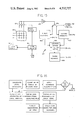
- FIG. 14 a simplified block diagram of the processor and control system for my fruit harvester is shown.
- a central processing unit (CPU) 102 is provided and is programmed to perform the described functions.
- Camera 16 is provided with two filters F 1 , 18 and F 2 , 19. Filters 18 and 19 are selectively used in accordance with a signal to camera filter control 13 from CPU 102. The operation of camera filter control 13 will be described in more detail hereinafter.
- the optical center line of camera 16 is at the geometrical center of housing 12 and coincident with the aperture center line seen in FIG. 1.
- lights 14 are flashed momentarily, producing intense wide spectrum illumination over the entire picking zone which is to be understood to be a truncated pyramidal zone defined by aperture 11 of module 10 and all of the tree within the field of view of camera 16. This may be best understood with reference to FIG. 18 with the truncated pyramid being defined by solid ray lines 6 and aperture 11.
- Camera 16, which will have a resolution of 65,536 pixels, will produce an analog video signal in accordance with the reflected light from the leaves, limbs, and fruit onto its light sensitive matrix.
- the camera scanning system therefore produces an analog video output which is fed to analog to digital (A/D) converter 103, converting the analog signal to a digital bit stream.
- the digital bit stream is processed by brightness discriminator 104, which as will be discussed hereinafter, identifies reflections indicative of fruits, notes the X-Y coordinates of each such fruit, and stores these coordinates in X-Y coordinate memory 105.
- brightness discriminator 104 identifies reflections indicative of fruits, notes the X-Y coordinates of each such fruit, and stores these coordinates in X-Y coordinate memory 105.
- FIG. 18 four fruits are shown, each lying on a different Z axis with respect to camera 16.
- Each Z axis intersects the plane defining aperture 11 at a different point indicated by the small crosses.
- the X-Y coordinates for the example of FIG. 18 stored in memory 105 would be that of the four crosses indicated. It is to be understood that the length of axes Z 0 , Z 1 , Z 2 , and Z 3 are not
- CPU 102 operates scissors control 20 to move camera 16 upward and to center the proximal end of picker arm assembly 21 at the exact center point of camera 16 at the time of performing the mapping function.
- arm 22 is extended along the axis Z 1 by moving vertical motor and drive 25 to the Y coordinate and horizontal motor and drive 27 to the X coordinate in aperture 11, then the picker arm Z axis will be coincident with axis Z 1 .
- the CPU will successively move arm 22 by means of vertical motor and drive 25 and horizontal motor and drive 27 to each of the X-Y coordinates identified and stored in memory 105.
- any sequencing operation may be performed, I prefer to start in the upper left-hand corner of aperture 11 and scan back and forth to each successive X coordinate and dropping down vertically to each successive Y coordinate.
- CPU 102 will instruct motor control 106 to operate the appropriate picking arm motors 28, M 1-4 to rapidly extend the arm until the fruit indicated along a particular axis is located and severed.
- CPU 102 instructs motor control 106 to extend the severance head along a particular Z axis, it also energizes nutation motor drive 170.
- the illumination from high intensity lamp 138 emanating through protective plate 162 will therefore describe a circular pattern.
- a signal will be produced by quad detector 132.
- This signal will be received by the CPU which instructs the motor control to slow down the advance of the severance head 30.
- the quad detector 132 at the same time, provides signals to the CPU which indicate the direction and magnitude that the reflected light is off center from the quad boresight.
- the CPU thereafter controls vertical motor and drive 25 and horizontal motor and drive 27 to bring the center line or boresight of the quad detector 132 to be aligned with the center of reflection from a fruit.
- arm motors 28 are monitored by current pickup 107 and sensor circuits 108 to measure the load on the motors. If, during its extension, severance head 30 contacts a limb or other non-flexible obstacle, the motor current will rise and motor current sensors 108 will instruct the CPU 102 to stop nutation and to withdraw the severance head 30.
- a fruit will be approached and will enter protective plate 162, operating at least three of the tactile sensors 154.
- the CPU 102 notes this occurrence and stops the forward progress of the picker arm 22 via motor control 106 and energizes grasp motor 148.
- Current sensor 109 indicates to the CPU when the fruit is firmly grasped, shutting off grasp motor 148 and energizing clutch solenoid 111.
- the CPU 102 then energizes twist motor 145 and bend motor 151. This causes the severance head 30 to bend sharply and also to twist, severing the fruit from its stem.
- Current sensors 109 will sense the decrease in load on the bend and twist motors when the fruit breaks free. It therefore signals the CPU to stop movement of the severance head 30 and to retract the picking arm 22.
- this action produces a signal at the CPU 102 which is programmed to retract the severance head 30 and to move the picker 22 arm to a slightly different Z axis and to continue seeking.
- the CPU has been monitoring the position of the collection arm 24 and controlling collection arm motors 26 to follow the picking arm with the collection cup 35 just below and to the rear of severance head 30.
- the CPU notes when the severance head 30 is over collection cup 35 and at that time releases grippers 31, permitting the fruit to drop into the collection cup.
- the collection cup can hold several fruit and is dumped by collection cup motor 23 into gutter 36 the first time that the cup is near gutter 36.
- FIG. 13 shows the results of tests on reflectance of citrus fruit and tree leaves. These data were taken from "Reflectance Properties of Citrus Fruit", J.J. Gaffney, pp. 310-314, Transactions of the ASAE, 1973 and “Basic Consideration in Mechanizing Citrus Harvest", Schertz and Brown, pp. 343-346, Transactions of the ASAE, 1968.
- navel oranges and valencia oranges reflect from about 60% to 85% of incident light in the range of 600 nm to 700 nm, while navel orange tree leaves and green valencia oranges reflect from about 8% to 25% of the light in the same portion of the spectrum. It will also be noted that the reflectance of the navel orange tree leaf is on the order of 45% in the 750-800 nm range, while green valencia oranges have a reflectance of about 85% in this range.
- the canopy depth of a tree may be from 1-3 meters, depending on the age of the tree and the amount of hedging performed.
- the light from light banks 14 reflected from the face of the tree near aperture 11 will be of a much greater intensity than light from objects at the back of the canopy.
- the intensity of reflected light from the rear of the canopy indicative of a fruit could be less than that from leaves at the front of the canopy. Therefore, I prefer to work with ratios of reflectance rather than absolute reflectance in identifying fruit and discriminating fruit from leaves and other background material.
- This approach depends, as may be noted from FIG. 13, on the reflectance ratio which is plotted as a solid line for navel oranges and indicates that the ratio of reflectance from a navel orange tree leaf to a navel orange is about 10:1 in the 600-700 nm range and about 1:1 to 1-1/2:1 in the 750-800 nm range.
- the brightness discriminator 104 in FIG. 12 therefore determines and stores the brightness level using a filter F 1 , 18, in the range 600-690 nm in front of the camera, storing the brightness for each pixel.
- the camera filter control 13 then removes filter F 1 , 18, and substitutes filter F 2 , 19, which may have a pass band in the range of 750-850 nm.
- Brightness discriminator 104 then stores the brightness level for each pixel viewed through filter F 2 , 19. Details of the discriminator are given in the simplified block diagram of FIG. 15 in which a small segment 180 of the 256 ⁇ 256 of the camera array is shown.
- Pixel clock 183 synchronized by sync pulses locked to the CPU clock read out an analog video signal which is digitized by A/D converter 103.
- the signals produced using F 1 (18) are stored in digital form in first memory 185, while signals from F 2 (19) are stored in second memory 187.
- Switch 186 is controlled by the camera filter control 13 to address the proper memory.
- CPU 102 then instructs ratio computer 188 to make a measurement of the ratios of illumination and to store each ratio in third memory 189
- the first step is to calculate the points of local maximas over the picking zone. Preferably, this operation is performed by a thresholding of the ratios to determine those representing reflected light in the yellow-orange spectrum.
- the X-Y coordinate of each maxima is flagged and 1,024 zones are defined from the total of 65,536 pixels. Each zone is identified by an X-Y coordinate and whether fruit appears in a zone is determined.
- the CPU then orders the zones in the sequence in which the fruit is to be picked.
- the processor then initiates the picking sequence with the picking arm moving to each X-Y coordinate defined as a maxima and performing a nutating search.
- the nutating search mode also depends upon reflection of light to detect when the picker arm 22 is aligned with a fruit. Since the picker arm extends along the direction of the Z axis for each X-Y coordinate for which a maxima has been defined, it will approach very closely to any fruit along that axis. The reflection ratios are not significant in this case due to the short range. Therefore, a filter 133 in front of quad detector 132 is selected to be responsive in the yellow and orange region of the spectrum; i.e., 600-690 nm. Since the light beam from lamp 138 is concentrated, quad sensor 132 will receive reflections from leaves and fruit directly in the path of the extending arm 22 with the bright or highly reflective areas indicative of the presence of fruit.
- FIG. 16 Also shown in FIG. 16 is an optional step which determines whether it is economical to pick fruit from a particular zone.
- the computer counts the number of identified picking points or maximas and compares this number to a predetermined number for which picking is cost effective. If the count exceeds the cost effective threshold, the process is continued. If not, the module is moved to a new picking zone and the mapping process is repeated. It may be noted that after picking a picking zone, the picked area may be quickly remapped, and the economic algorithm applied to determine if a significant amount of fruit was missed.
- a prime mover 200 is provided which may be a gasoline, diesel, or propane engine, or alternatively, a pick-off from the tractor engine.
- the prime mover may drive ac and dc generators 202 and 204, respectively, to furnish ac power and dc power to the system.
- the prime mover also operates air pump 208 which furnishes filtered, dried, and cooled air via regulator 212 to the picking arm for cooling its lamp and electronics as well as to keep the optical system clear of condensation and debris.
- air conditioner 214 driven from the prime mover and utilize the cool air therefrom to air pump 208.
- An insulated housing 216 is provided to house the computer and electronic controls 218 and the atmosphere therein controlled by air conditioner 214 to maintain the computer and electronic controls 218 at the desired temperature and humidity.
- a hydraulic system 206 may be included and a number of the elements of the harvester may be driven by hydraulic motors or actuators if desired.
Abstract
Description
Claims (39)
Priority Applications (5)
| Application Number | Priority Date | Filing Date | Title |
|---|---|---|---|
| US06/537,833 US4532757A (en) | 1983-09-30 | 1983-09-30 | Robotic fruit harvester |
| IL73070A IL73070A (en) | 1983-09-30 | 1984-09-26 | Robotic fruit harvester |
| IT22888/84A IT1176845B (en) | 1983-09-30 | 1984-09-28 | ROBOTIC FRUIT COLLECTOR |
| ES536384A ES8600845A1 (en) | 1983-09-30 | 1984-09-28 | Robotic fruit harvester |
| JP59203958A JPS6098909A (en) | 1983-09-30 | 1984-09-28 | Robot type fruit harvester |
Applications Claiming Priority (1)
| Application Number | Priority Date | Filing Date | Title |
|---|---|---|---|
| US06/537,833 US4532757A (en) | 1983-09-30 | 1983-09-30 | Robotic fruit harvester |
Publications (1)
| Publication Number | Publication Date |
|---|---|
| US4532757A true US4532757A (en) | 1985-08-06 |
Family
ID=24144298
Family Applications (1)
| Application Number | Title | Priority Date | Filing Date |
|---|---|---|---|
| US06/537,833 Expired - Fee Related US4532757A (en) | 1983-09-30 | 1983-09-30 | Robotic fruit harvester |
Country Status (5)
| Country | Link |
|---|---|
| US (1) | US4532757A (en) |
| JP (1) | JPS6098909A (en) |
| ES (1) | ES8600845A1 (en) |
| IL (1) | IL73070A (en) |
| IT (1) | IT1176845B (en) |
Cited By (94)
| Publication number | Priority date | Publication date | Assignee | Title |
|---|---|---|---|---|
| EP0194234A1 (en) * | 1985-02-04 | 1986-09-10 | MGZ S.p.A. | Apparatus for the automation of operative systems with mechanical hand or the like |
| US4718223A (en) * | 1985-10-17 | 1988-01-12 | Kubota, Ltd. | Fruit harvesting apparatus |
| FR2605834A1 (en) * | 1986-11-05 | 1988-05-06 | Pellenc & Motte | ROBOTIC MACHINE, IN PARTICULAR FOR FRUIT HARVESTING |
| US4838010A (en) * | 1987-06-29 | 1989-06-13 | Deere & Company | Electronics enclosure for an agricultural combine |
| US4843561A (en) * | 1985-05-01 | 1989-06-27 | Sun Controls Design, Inc. | Apparatus for locating and manipulating agricultural products |
| US4873644A (en) * | 1987-09-16 | 1989-10-10 | Kubota, Ltd. | Guide system for a working machine having a product identifying system |
| US5005347A (en) * | 1990-01-12 | 1991-04-09 | Du-Kedem Technologies, Ltd. | Fruit picking device |
| GB2237491A (en) * | 1989-11-03 | 1991-05-08 | Priorlucky Ltd | Harvesting of delicate produce |
| FR2658624A1 (en) * | 1990-02-22 | 1991-08-23 | Sagem | System for detecting objects to be located in a scene (visual environment), especially for fruit-picking robots |
| DE4116728A1 (en) * | 1990-05-24 | 1991-12-19 | Mezoegazdasagi Es Elelmiszerip | Fruit harvester with video camera on gripper head - has horizontal holder with vertical rotary axis with articulated parallel arms with gripper head |
| ES2036909A1 (en) * | 1990-04-18 | 1993-06-01 | Ind Albajar S A | Artificial vision system for the robotic collection of fruits |
| US5253302A (en) * | 1989-02-28 | 1993-10-12 | Robert Massen | Method and arrangement for automatic optical classification of plants |
| WO1994006275A1 (en) * | 1990-12-07 | 1994-03-31 | Doll Fahrzeugbau Gmbh | Disbrancher |
| US5471827A (en) * | 1991-07-09 | 1995-12-05 | Ccm Beheer B.V. | Device for the automatic selective harvesting of mushrooms |
| US5544474A (en) * | 1995-02-21 | 1996-08-13 | Finkelstein; Zvi | System for harvesting crop items and crop harvesting tools used therewith |
| US5610816A (en) * | 1992-09-15 | 1997-03-11 | Samsung Heavy Industries, Co. | Automatic steering method and apparatus for a non- railed transfer crane |
| US5666792A (en) * | 1994-12-30 | 1997-09-16 | Mullins; Donald B. | Remotely guided brush cutting, chipping and clearing apparatus and method |
| FR2760595A1 (en) * | 1997-03-13 | 1998-09-18 | Tecnoma | Harvesting bunches of grapes |
| US6009186A (en) * | 1996-08-30 | 1999-12-28 | New Holland Braud S.A. | Method and apparatus for harvesting crop material |
| US6044316A (en) * | 1994-12-30 | 2000-03-28 | Mullins; Donald B. | Method and apparatus for navigating a remotely guided brush cutting, chipping and clearing apparatus |
| US6155489A (en) * | 1998-11-10 | 2000-12-05 | Ncr Corporation | Item checkout device including a bar code data collector and a produce data collector |
| NL1013780C2 (en) * | 1999-12-07 | 2001-06-08 | Inst Voor Milieu En Agritechni | Method for detection of objects in abundant water conditions, involves first spectral reflection survey of area to be investigated of frequencies around water absorption band |
| US6332573B1 (en) | 1998-11-10 | 2001-12-25 | Ncr Corporation | Produce data collector and produce recognition system |
| US6336051B1 (en) | 1997-04-16 | 2002-01-01 | Carnegie Mellon University | Agricultural harvester with robotic control |
| US6377881B1 (en) | 1994-12-30 | 2002-04-23 | Donald B. Mullins | GPS guided ground-clearing apparatus and method |
| US6431446B1 (en) | 1999-07-28 | 2002-08-13 | Ncr Corporation | Produce recognition system and method |
| US6520008B1 (en) * | 2000-09-19 | 2003-02-18 | Delaware Capital Formation Inc. | Hydraulic movement measuring system |
| US20040130714A1 (en) * | 2001-03-22 | 2004-07-08 | Werner Gellerman | Optical method and apparatus for determining status of agricultural products |
| WO2006013593A1 (en) * | 2004-08-06 | 2006-02-09 | Valente Pali Precompressi Srl | Automated fruit and vegetables picker |
| ES2253135A1 (en) * | 2006-01-31 | 2006-05-16 | Universidad Politecnica De Madrid | Computer vision system for picking small row-cultivated fruits |
| US20060101797A1 (en) * | 2004-11-10 | 2006-05-18 | Beheersmaatschappij G.A.Ch.M. Jentjens B.V. | Device for working crops that grow on stalks |
| US20060150602A1 (en) * | 2005-01-07 | 2006-07-13 | Stimmann Eric M | Method and apparatus for remotely assisted harvester |
| US20080010961A1 (en) * | 2006-07-13 | 2008-01-17 | George Gray | Self Propelled Robotic Fresh Picker |
| ES2296452A1 (en) * | 2005-06-29 | 2008-04-16 | Universidad Politecnica De Madrid | Detector for vegetable stem and stalk, has laser line that is diode laser spot with conventional lens that spreads light plane at angle to produce mark, and images of scene are taken by vision sensor |
| US20090293442A1 (en) * | 2008-05-05 | 2009-12-03 | Chu-Yin Chang | Flexible robotic manipulation mechanism |
| US20090320430A1 (en) * | 2005-04-22 | 2009-12-31 | Green Automation Ltd Oy | Apparatus for picking mushrooms |
| US20100037583A1 (en) * | 2008-02-13 | 2010-02-18 | Picker Technologies Llc | Mobile system for improving the picking and preliminary processing of apples, citrus, stone fruit and like objects |
| WO2010063075A1 (en) * | 2008-12-03 | 2010-06-10 | Magnificent Pty Ltd | Crop picking device and method |
| US20110022231A1 (en) * | 2009-07-25 | 2011-01-27 | Jeffrey Walker | Apparatuses, Systems and Methods for Automated Crop Picking |
| US20110046785A1 (en) * | 2008-04-14 | 2011-02-24 | Ronald Zeelen | Method and device for the removal of a leaf from a crop |
| US20110047951A1 (en) * | 2009-08-25 | 2011-03-03 | Francis Wilson Moore | Fruit tree pruner and harvesting machine |
| US20110047955A1 (en) * | 2009-09-01 | 2011-03-03 | Dietrich Charles E | Pneumatic fruit decelerator apparatus and method |
| WO2011032226A1 (en) * | 2009-09-18 | 2011-03-24 | Fada Pty Ltd | A process and apparatus for grading and packing fruit |
| US20130064950A1 (en) * | 2011-09-09 | 2013-03-14 | Joseph A. Randazzo | Method, system, and apparatus for automated destemming |
| US20140230391A1 (en) * | 2013-02-20 | 2014-08-21 | Deere And Company | Per plant crop sensing resolution |
| US8997446B2 (en) | 2011-10-17 | 2015-04-07 | Dbr Conveyor Concepts, Llc | Pneumatic fruit decelerator body |
| US20160057940A1 (en) * | 2014-07-21 | 2016-03-03 | The Penn State Research Foundation | Selective automated blossom thinning |
| US9462749B1 (en) | 2015-04-24 | 2016-10-11 | Harvest Moon Automation Inc. | Selectively harvesting fruits |
| US9468152B1 (en) | 2015-06-09 | 2016-10-18 | Harvest Moon Automation Inc. | Plant pruning and husbandry |
| US9480202B2 (en) | 2013-12-20 | 2016-11-01 | Harvest Croo, Llc | Automated selective harvesting of crops |
| US9532508B1 (en) * | 2015-04-27 | 2017-01-03 | X Development Llc | Tagging of fruit-producing flowers for robotic selective harvesting |
| US9554513B2 (en) | 2013-12-20 | 2017-01-31 | Harvest Croo, Llc | Automated selective harvesting of crops with continuous offload |
| US20170094909A1 (en) * | 2015-10-05 | 2017-04-06 | Amrita Vishwa Vidyapeetham | Method and Apparatus for Harvesting Produce |
| US20170172075A1 (en) * | 2015-12-21 | 2017-06-22 | International Business Machines Corporation | Autonomous mobile platform and variable rate irrigation method for preventing frost damage |
| CN107018754A (en) * | 2017-04-26 | 2017-08-08 | 广西职业技术学院 | Automatic classification orange picking machine |
| WO2017172889A1 (en) * | 2016-03-29 | 2017-10-05 | Monsanto Technology Llc | Stem sensor |
| US9804604B2 (en) | 2013-08-16 | 2017-10-31 | Husqvarna Ab | Intelligent grounds management system integrating robotic rover |
| BE1024167B1 (en) * | 2017-03-22 | 2017-11-23 | Octinion Bvba | DEVICE FOR PICKING FRUIT WITH AN IMPROVED ROBOT ARM |
| US20170341222A1 (en) * | 2016-05-26 | 2017-11-30 | Seiko Epson Corporation | Horizontally articulated robot |
| WO2018015416A1 (en) | 2016-07-19 | 2018-01-25 | Octinion Bvba | Device for picking fruit having an improved robot arm |
| US9888631B2 (en) | 2013-12-20 | 2018-02-13 | Harvest Croo, Llc | Foliage holding |
| US9888630B2 (en) | 2013-12-20 | 2018-02-13 | Harvest Croo, Llc | Robot positioning with station-keeping |
| US9897429B2 (en) | 2013-12-20 | 2018-02-20 | Harvest Croo, Llc | Harvester suspension |
| US9913428B2 (en) | 2013-12-20 | 2018-03-13 | Harvest Croo, Llc | Individual plant location positioning |
| US9928584B2 (en) | 2016-07-11 | 2018-03-27 | Harvest Moon Automation Inc. | Inspecting plants for contamination |
| US9965845B2 (en) | 2016-07-11 | 2018-05-08 | Harvest Moon Automation Inc. | Methods and systems for inspecting plants for contamination |
| CN108056073A (en) * | 2018-02-01 | 2018-05-22 | 重庆京渝瑞基测控仪器仪表制造有限公司 | Full intelligent flexible sericulture system |
| US10059001B2 (en) * | 2013-10-31 | 2018-08-28 | Seiko Epson Corporation | Robot control device, robot system, and robot |
| US20180263188A1 (en) * | 2015-09-18 | 2018-09-20 | Carnegie Mellon University | A Self-Guided Blossom Picking Device |
| DE102017204158A1 (en) * | 2017-03-14 | 2018-09-20 | Robert Bosch Gmbh | A method of detecting at least one reproductive organ of a plant |
| CN108551882A (en) * | 2018-01-17 | 2018-09-21 | 吕梁学院 | A kind of tower leaf vegetables plantation picking robot |
| CN109121708A (en) * | 2018-07-25 | 2019-01-04 | 贵州省望谟县明灿芒果种植有限公司 | Mango device for picking |
| CN109847307A (en) * | 2019-01-29 | 2019-06-07 | 常州机电职业技术学院 | A kind of Basket-Shooting Robot |
| CN109874506A (en) * | 2019-04-08 | 2019-06-14 | 济南大学 | A kind of modularized bionic quadruped robot for spraying or picking |
| CN110249792A (en) * | 2019-07-05 | 2019-09-20 | 徐州市贾汪区贾汪镇宏发水蜜桃营销专业合作社 | A kind of device won convenient for honey peach |
| US10462972B2 (en) | 2016-09-15 | 2019-11-05 | Harvestmoore, L.L.C. | Methods for automated pruning and harvesting of fruit plants utilizing a graphic processor unit |
| US10542672B2 (en) * | 2016-08-03 | 2020-01-28 | D'arrigo Bros Co. Of California | Harvester and method for leafy plants |
| US20200128744A1 (en) * | 2018-10-29 | 2020-04-30 | Ffrobotics Ltd. | Robotic Fruit Harvesting Machine with Fruit-Pair Picking and Hybrid Motorized-Pneumatic robot arms |
| US10674666B2 (en) | 2017-05-18 | 2020-06-09 | Harvestmoore, L.L.C. | End effectors for harvesting machines and methods for using end effectors |
| US20200288636A1 (en) * | 2017-04-21 | 2020-09-17 | Xihelm Limited | Device for handling objects |
| US10785912B2 (en) | 2017-05-18 | 2020-09-29 | Harvestmoore, L.L.C. | End effectors for harvesting machines and methods for using end effectors |
| CN112385398A (en) * | 2020-10-22 | 2021-02-23 | 成都大学 | High-precision positioning method for automatic picking agricultural machine |
| US20210120739A1 (en) * | 2018-08-31 | 2021-04-29 | Abundant Robotics, Inc. | Multiple Channels for Receiving Dispensed Fruit |
| CN113317035A (en) * | 2021-05-25 | 2021-08-31 | 河南科技大学 | Low-suction-and-pull stem cutting and harvesting device for water-cultured lettuce |
| US20210267125A1 (en) * | 2020-02-28 | 2021-09-02 | The United States Of America, As Represented By The Secretary Of Agriculture | System and method for harvesting fruit |
| US11143261B2 (en) | 2017-05-10 | 2021-10-12 | Harvestmoore, L.L.C. | Shock damping systems and methods for using shock damping systems |
| US11202409B1 (en) * | 2021-02-05 | 2021-12-21 | Tortuga Agricultural Technologies, Inc. | Robotic harvesting system with a gantry system |
| US11212962B2 (en) | 2013-02-20 | 2022-01-04 | Deere & Company | Field condition determination |
| CN113940196A (en) * | 2021-09-30 | 2022-01-18 | 阿里云计算有限公司 | Picking robot, picking method, picking mechanism and boxing mechanism |
| US11285612B2 (en) * | 2019-08-20 | 2022-03-29 | X Development Llc | Coordinating agricultural robots |
| US11483975B2 (en) | 2013-12-20 | 2022-11-01 | Harvest Croo, Llc | Harvester pick deck suspension |
| US11528844B2 (en) * | 2019-11-21 | 2022-12-20 | Jiangxi University Of Science And Technology | Automatic harvesting and collecting device for sisal hemp leaves |
| US11760516B2 (en) | 2019-04-01 | 2023-09-19 | Harvest Croo, Llc | Automated packing of crops |
| US11957090B2 (en) | 2019-11-07 | 2024-04-16 | Harvestmoore, L.L.C. | Methods for pruning fruit plants |
Families Citing this family (4)
| Publication number | Priority date | Publication date | Assignee | Title |
|---|---|---|---|---|
| JP2732018B2 (en) * | 1993-10-12 | 1998-03-25 | 株式会社ミヤデン | Chip saw and method of manufacturing the same |
| CN109566092A (en) * | 2019-01-24 | 2019-04-05 | 西北农林科技大学 | A kind of fruit harvest machine people's control system for contest |
| CN113348871B (en) * | 2021-04-13 | 2023-05-02 | 陕西顶端果业科技有限公司 | Liftable rotary spindle platform |
| CN115380740B (en) * | 2022-09-22 | 2024-01-19 | 浙江工业大学之江学院 | Automatic plant mill of picking |
Citations (3)
| Publication number | Priority date | Publication date | Assignee | Title |
|---|---|---|---|---|
| US3925973A (en) * | 1974-11-19 | 1975-12-16 | Starkey Caroline J | Fruit picking apparatus |
| EP0053994A1 (en) * | 1980-12-09 | 1982-06-16 | Ecole Nationale Supérieure d'Electricité et de Radioélectricté de Bordeaux E.N.S.E.R.B. | Robot asparagus harvester |
| US4357790A (en) * | 1979-07-31 | 1982-11-09 | Tyros James C | Method and apparatus for picking olives or other fruits |
-
1983
- 1983-09-30 US US06/537,833 patent/US4532757A/en not_active Expired - Fee Related
-
1984
- 1984-09-26 IL IL73070A patent/IL73070A/en unknown
- 1984-09-28 ES ES536384A patent/ES8600845A1/en not_active Expired
- 1984-09-28 IT IT22888/84A patent/IT1176845B/en active
- 1984-09-28 JP JP59203958A patent/JPS6098909A/en active Pending
Patent Citations (4)
| Publication number | Priority date | Publication date | Assignee | Title |
|---|---|---|---|---|
| US3925973A (en) * | 1974-11-19 | 1975-12-16 | Starkey Caroline J | Fruit picking apparatus |
| US4357790A (en) * | 1979-07-31 | 1982-11-09 | Tyros James C | Method and apparatus for picking olives or other fruits |
| EP0053994A1 (en) * | 1980-12-09 | 1982-06-16 | Ecole Nationale Supérieure d'Electricité et de Radioélectricté de Bordeaux E.N.S.E.R.B. | Robot asparagus harvester |
| US4425751A (en) * | 1980-12-09 | 1984-01-17 | Ecole Nationale Superieure D'electricite Et De Radioelectricite De Bordeaux (E.N.S.E.R.B.) U.E.R. Derogatoire De L'universite De Bordeaux | Automatic asparagus picking machine |
Cited By (138)
| Publication number | Priority date | Publication date | Assignee | Title |
|---|---|---|---|---|
| EP0194234A1 (en) * | 1985-02-04 | 1986-09-10 | MGZ S.p.A. | Apparatus for the automation of operative systems with mechanical hand or the like |
| US4843561A (en) * | 1985-05-01 | 1989-06-27 | Sun Controls Design, Inc. | Apparatus for locating and manipulating agricultural products |
| US4718223A (en) * | 1985-10-17 | 1988-01-12 | Kubota, Ltd. | Fruit harvesting apparatus |
| US4975016A (en) * | 1986-11-05 | 1990-12-04 | Etablissements Pellenc et Motte, Centre National Du Machinisme Agricole Du Genie Rural, des Eaux et des Forets (csm agrcr) | Automated machine for detection and grasping of objects |
| FR2605834A1 (en) * | 1986-11-05 | 1988-05-06 | Pellenc & Motte | ROBOTIC MACHINE, IN PARTICULAR FOR FRUIT HARVESTING |
| EP0270469A1 (en) * | 1986-11-05 | 1988-06-08 | Etablissements Pellenc Et Motte | Robotic machine, especially for harvesting fruits |
| US4838010A (en) * | 1987-06-29 | 1989-06-13 | Deere & Company | Electronics enclosure for an agricultural combine |
| US4873644A (en) * | 1987-09-16 | 1989-10-10 | Kubota, Ltd. | Guide system for a working machine having a product identifying system |
| US5253302A (en) * | 1989-02-28 | 1993-10-12 | Robert Massen | Method and arrangement for automatic optical classification of plants |
| GB2237491A (en) * | 1989-11-03 | 1991-05-08 | Priorlucky Ltd | Harvesting of delicate produce |
| GB2237491B (en) * | 1989-11-03 | 1993-12-22 | Priorlucky Ltd | Harvesting of delicate produce |
| US5005347A (en) * | 1990-01-12 | 1991-04-09 | Du-Kedem Technologies, Ltd. | Fruit picking device |
| FR2658624A1 (en) * | 1990-02-22 | 1991-08-23 | Sagem | System for detecting objects to be located in a scene (visual environment), especially for fruit-picking robots |
| ES2036909A1 (en) * | 1990-04-18 | 1993-06-01 | Ind Albajar S A | Artificial vision system for the robotic collection of fruits |
| DE4116728A1 (en) * | 1990-05-24 | 1991-12-19 | Mezoegazdasagi Es Elelmiszerip | Fruit harvester with video camera on gripper head - has horizontal holder with vertical rotary axis with articulated parallel arms with gripper head |
| WO1994006275A1 (en) * | 1990-12-07 | 1994-03-31 | Doll Fahrzeugbau Gmbh | Disbrancher |
| US5746262A (en) * | 1990-12-07 | 1998-05-05 | Doll Fahrzeugbau Gmbh | Branch remover |
| US5471827A (en) * | 1991-07-09 | 1995-12-05 | Ccm Beheer B.V. | Device for the automatic selective harvesting of mushrooms |
| US5610816A (en) * | 1992-09-15 | 1997-03-11 | Samsung Heavy Industries, Co. | Automatic steering method and apparatus for a non- railed transfer crane |
| US6377881B1 (en) | 1994-12-30 | 2002-04-23 | Donald B. Mullins | GPS guided ground-clearing apparatus and method |
| US5666792A (en) * | 1994-12-30 | 1997-09-16 | Mullins; Donald B. | Remotely guided brush cutting, chipping and clearing apparatus and method |
| US6044316A (en) * | 1994-12-30 | 2000-03-28 | Mullins; Donald B. | Method and apparatus for navigating a remotely guided brush cutting, chipping and clearing apparatus |
| US5544474A (en) * | 1995-02-21 | 1996-08-13 | Finkelstein; Zvi | System for harvesting crop items and crop harvesting tools used therewith |
| WO1996025842A1 (en) * | 1995-02-21 | 1996-08-29 | Friedman, Mark, M. | A system for harvesting crop items and crop harvesting tools used therewith |
| US6009186A (en) * | 1996-08-30 | 1999-12-28 | New Holland Braud S.A. | Method and apparatus for harvesting crop material |
| FR2760595A1 (en) * | 1997-03-13 | 1998-09-18 | Tecnoma | Harvesting bunches of grapes |
| US6336051B1 (en) | 1997-04-16 | 2002-01-01 | Carnegie Mellon University | Agricultural harvester with robotic control |
| US6155489A (en) * | 1998-11-10 | 2000-12-05 | Ncr Corporation | Item checkout device including a bar code data collector and a produce data collector |
| US6332573B1 (en) | 1998-11-10 | 2001-12-25 | Ncr Corporation | Produce data collector and produce recognition system |
| US6845910B2 (en) | 1999-07-28 | 2005-01-25 | Ncr Corporation | Produce recognition system and method |
| US20020179710A1 (en) * | 1999-07-28 | 2002-12-05 | Yeming Gu | Produce recognition system and method |
| US6431446B1 (en) | 1999-07-28 | 2002-08-13 | Ncr Corporation | Produce recognition system and method |
| NL1013780C2 (en) * | 1999-12-07 | 2001-06-08 | Inst Voor Milieu En Agritechni | Method for detection of objects in abundant water conditions, involves first spectral reflection survey of area to be investigated of frequencies around water absorption band |
| US6520008B1 (en) * | 2000-09-19 | 2003-02-18 | Delaware Capital Formation Inc. | Hydraulic movement measuring system |
| US7215420B2 (en) | 2001-03-22 | 2007-05-08 | Werner Gellerman | Optical method and apparatus for determining status of agricultural products |
| US20040130714A1 (en) * | 2001-03-22 | 2004-07-08 | Werner Gellerman | Optical method and apparatus for determining status of agricultural products |
| WO2006013593A1 (en) * | 2004-08-06 | 2006-02-09 | Valente Pali Precompressi Srl | Automated fruit and vegetables picker |
| US20060101797A1 (en) * | 2004-11-10 | 2006-05-18 | Beheersmaatschappij G.A.Ch.M. Jentjens B.V. | Device for working crops that grow on stalks |
| US20060150602A1 (en) * | 2005-01-07 | 2006-07-13 | Stimmann Eric M | Method and apparatus for remotely assisted harvester |
| US20090320430A1 (en) * | 2005-04-22 | 2009-12-31 | Green Automation Ltd Oy | Apparatus for picking mushrooms |
| US8033087B2 (en) * | 2005-04-22 | 2011-10-11 | Green Automation Ltd Oy | Apparatus for picking mushrooms |
| ES2296452A1 (en) * | 2005-06-29 | 2008-04-16 | Universidad Politecnica De Madrid | Detector for vegetable stem and stalk, has laser line that is diode laser spot with conventional lens that spreads light plane at angle to produce mark, and images of scene are taken by vision sensor |
| ES2253135A1 (en) * | 2006-01-31 | 2006-05-16 | Universidad Politecnica De Madrid | Computer vision system for picking small row-cultivated fruits |
| WO2007088225A1 (en) * | 2006-01-31 | 2007-08-09 | Universidad Politécnica de Madrid | Computer vision system for picking small row-cultivated fruits |
| US20080010961A1 (en) * | 2006-07-13 | 2008-01-17 | George Gray | Self Propelled Robotic Fresh Picker |
| US7540137B2 (en) | 2006-07-13 | 2009-06-02 | George Gray | Self propelled robotic fresh picker |
| US20100037583A1 (en) * | 2008-02-13 | 2010-02-18 | Picker Technologies Llc | Mobile system for improving the picking and preliminary processing of apples, citrus, stone fruit and like objects |
| US20110126505A1 (en) * | 2008-02-13 | 2011-06-02 | Picker Technologies Llc | Mobile system for improving the picking and preliminary processing of apples, citrus, stone fruit and like objects |
| US7882686B2 (en) * | 2008-02-13 | 2011-02-08 | Picker Technologies Llc | Mobile system for improving the picking and preliminary processing of apples, citrus, stone fruit and like objects |
| CN101977494A (en) * | 2008-02-13 | 2011-02-16 | 匹克技术公司 | Mobile system for improving the picking and preliminary processing of apples, citrus, stone fruit and like objects |
| CN101977494B (en) * | 2008-02-13 | 2017-03-29 | 匹克技术公司 | Improve the mobile system of the harvesting and primary processing of the similar objects such as apple, oranges and tangerines, drupe |
| US8666552B2 (en) * | 2008-04-14 | 2014-03-04 | Ronald Zeelen | Method and device for the removal of a leaf from a crop |
| US20110046785A1 (en) * | 2008-04-14 | 2011-02-24 | Ronald Zeelen | Method and device for the removal of a leaf from a crop |
| US20090293442A1 (en) * | 2008-05-05 | 2009-12-03 | Chu-Yin Chang | Flexible robotic manipulation mechanism |
| US9357708B2 (en) * | 2008-05-05 | 2016-06-07 | Energid Technologies Corporation | Flexible robotic manipulation mechanism |
| WO2010063075A1 (en) * | 2008-12-03 | 2010-06-10 | Magnificent Pty Ltd | Crop picking device and method |
| WO2011017061A1 (en) * | 2009-07-25 | 2011-02-10 | Intelligent Farm Machines, Llc | Apparatuses, systems and methods for automated crop picking |
| US20110022231A1 (en) * | 2009-07-25 | 2011-01-27 | Jeffrey Walker | Apparatuses, Systems and Methods for Automated Crop Picking |
| US9861038B2 (en) | 2009-08-25 | 2018-01-09 | Harvestmoore, L.L.C. | Agriculture methods using stick images of plants |
| US9226446B2 (en) | 2009-08-25 | 2016-01-05 | Francis Wilson Moore | Robotic fruit tree pruner and harvester machine |
| US20110047951A1 (en) * | 2009-08-25 | 2011-03-03 | Francis Wilson Moore | Fruit tree pruner and harvesting machine |
| US9877428B2 (en) | 2009-08-25 | 2018-01-30 | Harvestmoore, L.L.C. | Agriculture vehicles |
| US20110047955A1 (en) * | 2009-09-01 | 2011-03-03 | Dietrich Charles E | Pneumatic fruit decelerator apparatus and method |
| US7926252B2 (en) * | 2009-09-01 | 2011-04-19 | Dbr Conveyor Concepts, Llc | Pneumatic fruit decelerator apparatus and method |
| WO2011032226A1 (en) * | 2009-09-18 | 2011-03-24 | Fada Pty Ltd | A process and apparatus for grading and packing fruit |
| US20130064950A1 (en) * | 2011-09-09 | 2013-03-14 | Joseph A. Randazzo | Method, system, and apparatus for automated destemming |
| US8733240B2 (en) * | 2011-09-09 | 2014-05-27 | Joseph A. Randazzo | System for automated destemming |
| US8997446B2 (en) | 2011-10-17 | 2015-04-07 | Dbr Conveyor Concepts, Llc | Pneumatic fruit decelerator body |
| US11212962B2 (en) | 2013-02-20 | 2022-01-04 | Deere & Company | Field condition determination |
| US10178828B2 (en) * | 2013-02-20 | 2019-01-15 | Deere & Company | Per plant crop sensing resolution |
| US20140230391A1 (en) * | 2013-02-20 | 2014-08-21 | Deere And Company | Per plant crop sensing resolution |
| US9804604B2 (en) | 2013-08-16 | 2017-10-31 | Husqvarna Ab | Intelligent grounds management system integrating robotic rover |
| US10059001B2 (en) * | 2013-10-31 | 2018-08-28 | Seiko Epson Corporation | Robot control device, robot system, and robot |
| US9480202B2 (en) | 2013-12-20 | 2016-11-01 | Harvest Croo, Llc | Automated selective harvesting of crops |
| US10721868B2 (en) | 2013-12-20 | 2020-07-28 | Harvest Croo, Llc | Robot positioning with station-keeping |
| US9888631B2 (en) | 2013-12-20 | 2018-02-13 | Harvest Croo, Llc | Foliage holding |
| US10420283B2 (en) | 2013-12-20 | 2019-09-24 | Harvest Croo, Llc | Automated selective harvesting of crops |
| US9554513B2 (en) | 2013-12-20 | 2017-01-31 | Harvest Croo, Llc | Automated selective harvesting of crops with continuous offload |
| US9888630B2 (en) | 2013-12-20 | 2018-02-13 | Harvest Croo, Llc | Robot positioning with station-keeping |
| US11483975B2 (en) | 2013-12-20 | 2022-11-01 | Harvest Croo, Llc | Harvester pick deck suspension |
| US9897429B2 (en) | 2013-12-20 | 2018-02-20 | Harvest Croo, Llc | Harvester suspension |
| US9913428B2 (en) | 2013-12-20 | 2018-03-13 | Harvest Croo, Llc | Individual plant location positioning |
| US20160057940A1 (en) * | 2014-07-21 | 2016-03-03 | The Penn State Research Foundation | Selective automated blossom thinning |
| US10448578B2 (en) * | 2014-07-21 | 2019-10-22 | The Penn State Research Foundation | Selective automated blossom thinning |
| US11304374B2 (en) | 2014-07-21 | 2022-04-19 | The Penn State Research Foundation | Selective automated blossom thinning |
| US9462749B1 (en) | 2015-04-24 | 2016-10-11 | Harvest Moon Automation Inc. | Selectively harvesting fruits |
| US9532508B1 (en) * | 2015-04-27 | 2017-01-03 | X Development Llc | Tagging of fruit-producing flowers for robotic selective harvesting |
| US10602664B1 (en) * | 2015-04-27 | 2020-03-31 | X Development Llc | Tagging of fruit-producing flowers for robotic selective harvesting |
| US9913429B1 (en) * | 2015-04-27 | 2018-03-13 | X Development Llc | Tagging of fruit-producing flowers for robotic selective harvesting |
| US9468152B1 (en) | 2015-06-09 | 2016-10-18 | Harvest Moon Automation Inc. | Plant pruning and husbandry |
| US20180263188A1 (en) * | 2015-09-18 | 2018-09-20 | Carnegie Mellon University | A Self-Guided Blossom Picking Device |
| US11134617B2 (en) * | 2015-09-18 | 2021-10-05 | Carnegie Mellon University | Self-guided blossom picking device |
| US20170094909A1 (en) * | 2015-10-05 | 2017-04-06 | Amrita Vishwa Vidyapeetham | Method and Apparatus for Harvesting Produce |
| US11212964B2 (en) * | 2015-10-05 | 2022-01-04 | Amrita Vishwa Vidyapeetham | Method of controlling an automated drone for harvesting produce |
| US10555460B2 (en) * | 2015-10-05 | 2020-02-11 | Amrita Vishwa Vidyapeetham | Automated drone for harvesting produce |
| US10165736B2 (en) | 2015-12-21 | 2019-01-01 | International Business Machines Corporation | Autonomous mobile platform and variable rate irrigation method for preventing frost damage |
| US10172299B2 (en) * | 2015-12-21 | 2019-01-08 | International Business Machines Corporation | Autonomous mobile platform and variable rate irrigation method for preventing frost damage |
| US10219448B2 (en) | 2015-12-21 | 2019-03-05 | International Business Machines Corporation | Autonomous mobile platform and variable rate irrigation method for preventing frost damage |
| US20170172075A1 (en) * | 2015-12-21 | 2017-06-22 | International Business Machines Corporation | Autonomous mobile platform and variable rate irrigation method for preventing frost damage |
| US11246269B2 (en) | 2015-12-21 | 2022-02-15 | International Business Machines Corportation | Autonomous mobile platform and variable rate irrigation method for preventing frost damage |
| US10999977B2 (en) | 2016-03-29 | 2021-05-11 | Monsanto Technology Llc | Stem sensor |
| WO2017172889A1 (en) * | 2016-03-29 | 2017-10-05 | Monsanto Technology Llc | Stem sensor |
| US20170341222A1 (en) * | 2016-05-26 | 2017-11-30 | Seiko Epson Corporation | Horizontally articulated robot |
| US10919145B2 (en) * | 2016-05-26 | 2021-02-16 | Seiko Epson Corporation | Horizontally articulated robot |
| US10198806B2 (en) | 2016-07-11 | 2019-02-05 | Harvest Moon Automation Inc. | Methods and systems for inspecting plants for contamination |
| US9965845B2 (en) | 2016-07-11 | 2018-05-08 | Harvest Moon Automation Inc. | Methods and systems for inspecting plants for contamination |
| US9928584B2 (en) | 2016-07-11 | 2018-03-27 | Harvest Moon Automation Inc. | Inspecting plants for contamination |
| WO2018015416A1 (en) | 2016-07-19 | 2018-01-25 | Octinion Bvba | Device for picking fruit having an improved robot arm |
| US10542672B2 (en) * | 2016-08-03 | 2020-01-28 | D'arrigo Bros Co. Of California | Harvester and method for leafy plants |
| US10542671B2 (en) * | 2016-08-03 | 2020-01-28 | D'arrigo Bros Co. Of California | Harvester for leafy plants |
| US10462972B2 (en) | 2016-09-15 | 2019-11-05 | Harvestmoore, L.L.C. | Methods for automated pruning and harvesting of fruit plants utilizing a graphic processor unit |
| DE102017204158A1 (en) * | 2017-03-14 | 2018-09-20 | Robert Bosch Gmbh | A method of detecting at least one reproductive organ of a plant |
| BE1024167B1 (en) * | 2017-03-22 | 2017-11-23 | Octinion Bvba | DEVICE FOR PICKING FRUIT WITH AN IMPROVED ROBOT ARM |
| US20200288636A1 (en) * | 2017-04-21 | 2020-09-17 | Xihelm Limited | Device for handling objects |
| CN107018754A (en) * | 2017-04-26 | 2017-08-08 | 广西职业技术学院 | Automatic classification orange picking machine |
| US11143261B2 (en) | 2017-05-10 | 2021-10-12 | Harvestmoore, L.L.C. | Shock damping systems and methods for using shock damping systems |
| US10785912B2 (en) | 2017-05-18 | 2020-09-29 | Harvestmoore, L.L.C. | End effectors for harvesting machines and methods for using end effectors |
| US10674666B2 (en) | 2017-05-18 | 2020-06-09 | Harvestmoore, L.L.C. | End effectors for harvesting machines and methods for using end effectors |
| CN108551882A (en) * | 2018-01-17 | 2018-09-21 | 吕梁学院 | A kind of tower leaf vegetables plantation picking robot |
| CN108056073A (en) * | 2018-02-01 | 2018-05-22 | 重庆京渝瑞基测控仪器仪表制造有限公司 | Full intelligent flexible sericulture system |
| CN108056073B (en) * | 2018-02-01 | 2023-07-28 | 重庆京渝瑞基测控仪器仪表制造有限公司 | Full-intelligent flexible silkworm breeding system |
| CN109121708A (en) * | 2018-07-25 | 2019-01-04 | 贵州省望谟县明灿芒果种植有限公司 | Mango device for picking |
| US20210120739A1 (en) * | 2018-08-31 | 2021-04-29 | Abundant Robotics, Inc. | Multiple Channels for Receiving Dispensed Fruit |
| US20200128744A1 (en) * | 2018-10-29 | 2020-04-30 | Ffrobotics Ltd. | Robotic Fruit Harvesting Machine with Fruit-Pair Picking and Hybrid Motorized-Pneumatic robot arms |
| US11477942B2 (en) * | 2018-10-29 | 2022-10-25 | Ffrobotics Ltd. | Robotic fruit harvesting machine with fruit-pair picking and hybrid motorized-pneumatic robot arms |
| CN109847307B (en) * | 2019-01-29 | 2024-02-02 | 常州机电职业技术学院 | Shooting robot |
| CN109847307A (en) * | 2019-01-29 | 2019-06-07 | 常州机电职业技术学院 | A kind of Basket-Shooting Robot |
| US11760516B2 (en) | 2019-04-01 | 2023-09-19 | Harvest Croo, Llc | Automated packing of crops |
| CN109874506A (en) * | 2019-04-08 | 2019-06-14 | 济南大学 | A kind of modularized bionic quadruped robot for spraying or picking |
| CN110249792A (en) * | 2019-07-05 | 2019-09-20 | 徐州市贾汪区贾汪镇宏发水蜜桃营销专业合作社 | A kind of device won convenient for honey peach |
| US11285612B2 (en) * | 2019-08-20 | 2022-03-29 | X Development Llc | Coordinating agricultural robots |
| US11957090B2 (en) | 2019-11-07 | 2024-04-16 | Harvestmoore, L.L.C. | Methods for pruning fruit plants |
| US11528844B2 (en) * | 2019-11-21 | 2022-12-20 | Jiangxi University Of Science And Technology | Automatic harvesting and collecting device for sisal hemp leaves |
| US20210267125A1 (en) * | 2020-02-28 | 2021-09-02 | The United States Of America, As Represented By The Secretary Of Agriculture | System and method for harvesting fruit |
| CN112385398A (en) * | 2020-10-22 | 2021-02-23 | 成都大学 | High-precision positioning method for automatic picking agricultural machine |
| US11202409B1 (en) * | 2021-02-05 | 2021-12-21 | Tortuga Agricultural Technologies, Inc. | Robotic harvesting system with a gantry system |
| CN113317035A (en) * | 2021-05-25 | 2021-08-31 | 河南科技大学 | Low-suction-and-pull stem cutting and harvesting device for water-cultured lettuce |
| CN113940196A (en) * | 2021-09-30 | 2022-01-18 | 阿里云计算有限公司 | Picking robot, picking method, picking mechanism and boxing mechanism |
Also Published As
| Publication number | Publication date |
|---|---|
| JPS6098909A (en) | 1985-06-01 |
| IL73070A (en) | 1988-06-30 |
| ES536384A0 (en) | 1985-10-16 |
| IL73070A0 (en) | 1984-12-31 |
| IT8422888A0 (en) | 1984-09-28 |
| ES8600845A1 (en) | 1985-10-16 |
| IT1176845B (en) | 1987-08-18 |
Similar Documents
| Publication | Publication Date | Title |
|---|---|---|
| US4532757A (en) | Robotic fruit harvester | |
| US20110022231A1 (en) | Apparatuses, Systems and Methods for Automated Crop Picking | |
| US5544474A (en) | System for harvesting crop items and crop harvesting tools used therewith | |
| Li et al. | Review on fruit harvesting method for potential use of automatic fruit harvesting systems | |
| US4975016A (en) | Automated machine for detection and grasping of objects | |
| JP3131993B2 (en) | Visual devices such as fruit and vegetable harvesters | |
| US4843561A (en) | Apparatus for locating and manipulating agricultural products | |
| US9877428B2 (en) | Agriculture vehicles | |
| US20060150602A1 (en) | Method and apparatus for remotely assisted harvester | |
| Peterson et al. | A systems approach to robotic bulk harvesting of apples | |
| US11134617B2 (en) | Self-guided blossom picking device | |
| EP0593680B1 (en) | Device for the automatic selective harvesting of mushrooms | |
| CN113843810B (en) | Machine vision-based spheroidal fruit picking robot and fruit picking method thereof | |
| JP3277529B2 (en) | Fruit harvesting robot | |
| CA3128185A1 (en) | Crop harvesting robot | |
| US20230189713A1 (en) | Fruit picking robotic installation on platforms | |
| JP2024505669A (en) | Robotic harvesting system with gantry system | |
| JP3139074B2 (en) | Visual devices such as fruit harvesting robots | |
| Lee et al. | Development of a canopy volume reduction technique for easy assessment and harvesting of valencia citrus fruits | |
| JP3336663B2 (en) | Visual devices such as fruit harvesting robots | |
| JPH05168333A (en) | Fruit harvesting robot | |
| JPS5931618A (en) | Fruit harvesting apparatus | |
| Kurhade et al. | Review on “Automation in Fruit Harvesting | |
| JPH1042665A (en) | Image pick up device of robot for agricultural use | |
| HU210376B (en) | Fruit-picking apparatus and method for looking for fruits |
Legal Events
| Date | Code | Title | Description |
|---|---|---|---|
| AS | Assignment |
Owner name: MARTIN MARIETTA CORPORATION, 6801 ROCKLEDGE DRIVE, Free format text: ASSIGNMENT OF ASSIGNORS INTEREST.;ASSIGNOR:TUTLE, EDWARD G.;REEL/FRAME:004181/0131 Effective date: 19830929 |
|
| FEPP | Fee payment procedure |
Free format text: PAYOR NUMBER ASSIGNED (ORIGINAL EVENT CODE: ASPN); ENTITY STATUS OF PATENT OWNER: SMALL ENTITY |
|
| AS | Assignment |
Owner name: TUTLE, EDWARD G., 2601 SEABREEZE COURT, ORLANDO, F Free format text: ASSIGNMENT OF ASSIGNORS INTEREST.;ASSIGNOR:MARTIN MARIETTA CORPORATION, A CORP OF MD.;REEL/FRAME:004920/0854 Effective date: 19880728 |
|
| FEPP | Fee payment procedure |
Free format text: PAYOR NUMBER ASSIGNED (ORIGINAL EVENT CODE: ASPN); ENTITY STATUS OF PATENT OWNER: SMALL ENTITY Free format text: PAYER NUMBER DE-ASSIGNED (ORIGINAL EVENT CODE: RMPN); ENTITY STATUS OF PATENT OWNER: SMALL ENTITY |
|
| FPAY | Fee payment |
Year of fee payment: 4 |
|
| FPAY | Fee payment |
Year of fee payment: 8 |
|
| REMI | Maintenance fee reminder mailed | ||
| LAPS | Lapse for failure to pay maintenance fees | ||
| FP | Lapsed due to failure to pay maintenance fee |
Effective date: 19970806 |
|
| STCH | Information on status: patent discontinuation |
Free format text: PATENT EXPIRED DUE TO NONPAYMENT OF MAINTENANCE FEES UNDER 37 CFR 1.362 |