US4517430A - Microwave heating device with constant temperature control of the magnetron - Google Patents
Microwave heating device with constant temperature control of the magnetron Download PDFInfo
- Publication number
- US4517430A US4517430A US06/493,368 US49336883A US4517430A US 4517430 A US4517430 A US 4517430A US 49336883 A US49336883 A US 49336883A US 4517430 A US4517430 A US 4517430A
- Authority
- US
- United States
- Prior art keywords
- magnetron
- heating
- heating device
- magnetron tube
- set forth
- Prior art date
- Legal status (The legal status is an assumption and is not a legal conclusion. Google has not performed a legal analysis and makes no representation as to the accuracy of the status listed.)
- Expired - Fee Related
Links
Images


Classifications
-
- H—ELECTRICITY
- H05—ELECTRIC TECHNIQUES NOT OTHERWISE PROVIDED FOR
- H05B—ELECTRIC HEATING; ELECTRIC LIGHT SOURCES NOT OTHERWISE PROVIDED FOR; CIRCUIT ARRANGEMENTS FOR ELECTRIC LIGHT SOURCES, IN GENERAL
- H05B6/00—Heating by electric, magnetic or electromagnetic fields
- H05B6/64—Heating using microwaves
- H05B6/74—Mode transformers or mode stirrers
- H05B6/745—Rotatable stirrers
-
- H—ELECTRICITY
- H05—ELECTRIC TECHNIQUES NOT OTHERWISE PROVIDED FOR
- H05B—ELECTRIC HEATING; ELECTRIC LIGHT SOURCES NOT OTHERWISE PROVIDED FOR; CIRCUIT ARRANGEMENTS FOR ELECTRIC LIGHT SOURCES, IN GENERAL
- H05B6/00—Heating by electric, magnetic or electromagnetic fields
- H05B6/64—Heating using microwaves
- H05B6/66—Circuits
- H05B6/666—Safety circuits
-
- H—ELECTRICITY
- H05—ELECTRIC TECHNIQUES NOT OTHERWISE PROVIDED FOR
- H05B—ELECTRIC HEATING; ELECTRIC LIGHT SOURCES NOT OTHERWISE PROVIDED FOR; CIRCUIT ARRANGEMENTS FOR ELECTRIC LIGHT SOURCES, IN GENERAL
- H05B6/00—Heating by electric, magnetic or electromagnetic fields
- H05B6/64—Heating using microwaves
- H05B6/80—Apparatus for specific applications
- H05B6/806—Apparatus for specific applications for laboratory use
-
- H—ELECTRICITY
- H05—ELECTRIC TECHNIQUES NOT OTHERWISE PROVIDED FOR
- H05B—ELECTRIC HEATING; ELECTRIC LIGHT SOURCES NOT OTHERWISE PROVIDED FOR; CIRCUIT ARRANGEMENTS FOR ELECTRIC LIGHT SOURCES, IN GENERAL
- H05B2206/00—Aspects relating to heating by electric, magnetic, or electromagnetic fields covered by group H05B6/00
- H05B2206/04—Heating using microwaves
- H05B2206/043—Methods or circuits intended to extend the life of the magnetron
-
- H—ELECTRICITY
- H05—ELECTRIC TECHNIQUES NOT OTHERWISE PROVIDED FOR
- H05B—ELECTRIC HEATING; ELECTRIC LIGHT SOURCES NOT OTHERWISE PROVIDED FOR; CIRCUIT ARRANGEMENTS FOR ELECTRIC LIGHT SOURCES, IN GENERAL
- H05B2206/00—Aspects relating to heating by electric, magnetic, or electromagnetic fields covered by group H05B6/00
- H05B2206/04—Heating using microwaves
- H05B2206/046—Microwave drying of wood, ink, food, ceramic, sintering of ceramic, clothes, hair
Definitions
- This invention relates generally to microwave heating devices and specifically for such devices wherein the device may be used for drying materials containing water much faster than conventional heating structures particularly for use with laboratories and the like.
- a patent to Kaminaka U.S. Pat. No. 4,236,055 discloses a microwave oven employing a Triac 18 in the power circuit for the magnetron.
- a cooling fan 10 remains energized after the magnetron is switched off to cool the high voltage transformer 7, the microprocessor 2, and the magnetron 9.
- An object of the present invention is to provide a precisely controlled microwave heating device for use in drying materials containing water much faster than conventional heating devices.
- Another object of the present invention is to provide a microwave heating device which can pulse a magnetron at full power for varying periods of time in order to provide different heat outputs, in addition structure is included for energizing the magnetron for a portion of each input power cycle depending upon a heat output setting to provide very uniform heating, and additional structure is provided for holding the magnetron at practically a constant temperature for the purpose of providing a very steady power output.
- the overall heating device is very accurately controllable and predictable.
- a further additional object is to provide a heater and thermostat combination structure physically attachable to a magnetron tube of a microwave oven for holding the magnetron at a constant temperature during the stand-by period of the magnetron.
- the overall purpose being to provide microwave heating which is very predictable, resettable and repeatable in power output during each heating period.
- the present invention has a number of new and novel features. Among them are precise, accurate control of a heating device which is usable by laboratories and the like for heating test samples, and particularly for heating a number of such samples wherein it is highly desirable that the overall heating power be repeatable and reproducable almost identically to the ones therebefore.
- the microwave heating device of the present invention is especially designed for laboratory use. Its unique features provide the researcher, technologist, and technician with a new versatile heating device capable or rapid, large volume heating, finely controlled analytical heating of small samples, and extension of results from laboratory testing to industrial scale-up. Examples of general application for which the present invention can be used are as follows:
- Microwaves are short electromagnetic waves of the same family as those used in radio, TV, and radar. Although microwaves have no identifiable temperature of their own, they can create temperature rises in products and water. In the same manner as an electrical range, microwaves pass freely through the air until they encounter a resistive load. Water is resistant to microwaves and will absorb them, increasing its molecular activity to such an extent that heat is created through internal friction. Thus, heat generated by a microwave is the result of microwave interaction with water molecules contained in the samples.
- Microwaves which in character are short, straight waves, are reflected by metals. When transmitted into the microwave cavity, they are reflected off the metal walls, roof, and floor of the cavity and absorbed by the samples. Glass, paper, and most plastics are transparent to microwaves and will permit microwaves to pass through them with little or no absorption.
- Microwaves heat at a very fast rate, dependent upon the size of the load and output power. Therefore, it is the time setting and the power setting which must be varied according to the amount of sample mass being heated.
- the microwave oven needs no pre-heating period as does a conventional oven.
- any increase in heating time will cause an additional amount of microwave energy to be used to heat the sample.
- the present microwave heating device incorporates several component protection features.
- the oven has a thermal sensor to protect the magnetron tube from unintentional overheating, and a timer shuts off automatically to insure a longer life of all electrical components.
- FIG. 1 is a perspective view of the microwave heating device of the present invention
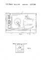
- FIG. 2A is a front view of the heating device and FIG. 2B is an enlarged front elevational view of the control panel per se of the heating device of FIGS. 1 and 2A;
- FIGS. 3A, 3B and 3C form a composite schematic diagram of the electrical control circuitry for the present invention
- FIG. 4 is an enlarged portion of the lower part of the FIG. 3B wiring showing the resistance heater circuit with thermostatic control;
- FIG. 5 is an enlarged portion of the lower part of the FIG. 3A wiring showing the magnetron controller with surge resistor and thermo protector;
- FIG. 7 is a schematic diagram showing the circuitry for the timer printed circuit board
- FIG. 8 is a top plan view of the microwave heating device of the present invention.
- FIGS. 9A and 9B are side elevational views of the front and rear of the the device.
- FIG. 10 is a side elevational view of the magnetron tube per se as modified for attachment of the resistance heater and thermostatic control therefor.
- reference numeral 10 indicates in general the heating device of the present invention.
- the basic housing structure 12 is of conventional microwave oven-type construction having a door 13 with handle 15, and has an inner chamber which supports the samples or other materials to be heated with appropriate microwave energy generating structure, i.e., a magnetron tube and system.
- the housing also contains the electrical wiring, the energizing and control elements for suitably energizing the magnetron tube, etc.
- a control panel 14 includes the switch elements which are user actuated to produce the various combinations of power output from the magnetron tube.
- FIGS. 2A and 2B show in greater detail the control panel 14 of FIG. 1.
- the first one 28 is for setting the time of heating.
- the other thumb wheel switch 30 determines the amount of additional time the vent blower is "on" independently of the microwave heating. The purpose of the vent being to exhaust vapors from the oven.
- Each control is set by the user of the device for the desired amount of time for the respective heating and venting cycles.
- the visual display indicates whatever setting the operator selects.
- a star button 24 is pressed when the operator is ready to start a desired heating cycle.
- the magnetron ready light 26 glows when the magnetron has been sufficiently heated to be at its best operating temperature, and is part of the very heart of the present invention. While microwave heating may be done with the ready light 26 "off", indicating that the magnetron is not up to desired operating temperature, the desirable benefits of the present invention will not be effected with such operation.
- the ready light 26 should be "on”, indicating that the magnetron is heated to the best operating temperature, and is being maintained at this temperature.
- Tests have been conducted which indicate that the increased efficiency and the new and unexpected results achieved by the present invention are definitely a function of the magnetron being operated at a predetermined degree of heat and its being maintained at this desired operating temperature during use of the device.
- the pilot light 27 glows whenever the "heat” and/or "vent” time cycles are energized.
- a heat time remaining window 34 will upon initial actuation of start button 24, indicate the same reading as the heat time set on dial 28. Then as the heating operation of the oven continues, appropriate circuitry within the oven will cause the LEDs to count down thus showing the remaining time in the heat cycle. For example, if the "heat" thumb wheel switch 28 is set for 10 minutes, initially upon depressing start button 24, the LEDs behind window 34 will indicate the number 10.0. As the heating cycle progresses and the time cycle expires, the LEDs will indicate 9.9 minutes, 9.8 minutes, etc. until the entire heat cycle is completed, at which time the LEDs will diminish to zero or become blank.
- LEDs light emitting diodes
- the venting cycle will then continue in the same manner. For example, if 25 minutes has been set into the thumb wheel vent time switch 30, when the heat time remaining window 34 indicates zero then almost simultaneously window 35 will indicate 25.0 minutes, and then descend to 24.9 minutes, 24.8 minutes, and so forth down to zero. When zero is reached the vent cycle will be ended. From the foregoing, it can be concluded that a vent cycle due to energization of the built-in blower motor is in effect at all times that the heating cycle itself is energized, and an additional venting cycle may follow as determined by the vent time set switch 30.
- the power control elements for the magnetron are arranged in the lower half of control panel 14. Mounted slightly below the center of the control panel are a plurality of nine push button switches 19. These switches control the percentage of power of the magnetron output in ten discreet steps. In none of the push buttons are depressed, then 100 percent of microwave power from the magnetron is effected. However, the actual power output from the magnetron can be varied from 10 percent to 90 percent of full power, in steps of 10 percent by depressing the appropriate button. For example, in the magnetron system wherein full power corresponds to approximately 650 watts, 90 percent power is approximately 585 watts, 80 percent power is approximately 520 watts, and so forth.
- the variable control element 18 at the bottom of the control panel is for pulsed power control.
- MAX the magnetron
- the dial 18 is rotated clockwise, the magnetron is energized in a pulsed manner "on” and “off” over a 12 second duty cycle. This effects the following pulsed power control of the magnetron.
- the magnetron is pulsed "on” for 1 second and is "off” for 11 seconds.
- the magnetron is pulsed "on” for 6 seconds and “off” for 6 seconds.
- the magnetron is pulsed "on” for 12 seconds and "off” for zero seconds, i.e., "on” continuously.
- the positions intermediate the ones listed are in direct proportion thereto.
- the percentage of power switches 19 and the pulsed power control 18 various combinations of output power can be achieved. For example, if button three is depressed for 30 percent power and the pulse power control is set at 4, then based on an overall total power output of 650 watts, 195 watts will be produced for 9.5 seconds and zero watts will be produced for 2.5 seconds.
- FIGS. 3A, 3B and 3C depict a composite schematic diagram of the electrical control circuitry. Looking at the upper portion of the FIG. 3C schematic, the electrical elements behind the heat time set switch can be seen.
- the switches S2A, S2B, S2C as appropriately turned by a user (Heat Time Set switch 28) to the desired heat time, are connected into the digital counter timer printed circuit board A10.
- the schematic diagram of FIG. 7 shows the electrical connections of timer A10.
- FIG. 3C just below the printed circuit board A10 are the switches S2D, S2E and S2F of the vent time set switch 30.
- panel lamps DS2 and DS3 being for the indication of energization of the heating (drying) and ventilation circuits (panel light 27), and the DS3 panel light indicating magnetron "ready” (light 26).
- DS2 being for the indication of energization of the heating (drying) and ventilation circuits (panel light 27), and the DS3 panel light indicating magnetron "ready” (light 26).
- the input from the power control schematic A20 FIG. 6
- the power transformer T2 the voltage control circuitry for the magnetron B1, and the Triac CR3 can be seen.
- the bottom of the schematic of FIG. 3A shows the varistor assembly CR4, and the magnetron controller R1.
- the surge resistor R2 and a thermoprotector S8 are provided for protection of the device.
- the interlock structure for the oven door, the connections for the stirrer motor B1, the heat relay K1 for magnetron energization, and the relay K2 for the vent blower motor B2 are shown.
- FIG. 4 is an enlarged portion of the schematic of FIG. 3 showing the magnetron heater resistor R4 and the magnetron thermostatic control S3. Both of these are physically and mechanically connected to the magnetron tube V1 in a manner to be shown and described below.
- FIG. 5 is an enlarged schematic view of FIG. 3A showing the magnetron controller R1, the surge resistor R2 and the thermoprotector S8 for the magnetron tube V1.
- FIG. 6 is a detailed schematic of the variable power control circuit with the nine push button, percent of power switches, as are provided on a printed circuit board. This is the portion indicated as A20 in the schematic of FIGS. 3C and 4.
- FIG. 7 is a schematic diagram of the timer printed circuit board indicated as A10 in the schematic of FIG. 3C. Neither FIG. 6 nor 7 will be described in detail since a functional narrative of the wiring schematic has already been set forth, and a detailed element by element discussion is not believed necessary. However, anyone with an electronics background should be able to indicate from the schematic diagrams the proper electrical hookup for a successful operating device.
- FIGS. 8 and 9A, 9B show respectively top and side views of the structural arrangement of the microwave oven of the present invention.
- the holding relays K1 and K2 are both shown, as well as an interior light DS4 for the oven.
- the top of door 13, handle 15, and the control panel 14 are also designated.
- the Triac CR3 is indicated by reference number 51
- the blower motor B2 the capacitor C1, the transformer T1, the varistor assembly CR4, and the magnetron tube V1 are all shown.
- FIG. 9A the magnetron controller R1 for changing the pulse power as mounted behind control knob 18 can be seen, also a magnetron filament transformer T2 is indicated by reference numeral 49, and the three interlock switches S5, S7 and S9 for the oven door.
- the magnetron tube V1 structurally is provided with tappings for mounting a metal support plate 16.
- the support plate 16 holds the heater resistance R4 as indicated by 216 for the purpose of providing a good heat conducting contact between the heater resistance R4 and the magnetron tube shell.
- 53 indicates the physical mounting of the thermostatic control S3 by means of a large head screw 72 directly to the magnetron tube casing.
- the thermoprotector switch S8 is physically attached at 55 to the magnetron tube 31, and the thermostatic control S3 is similarly physically attached by the additional tapped holes 153.
- the screws 116 physically attach and secure the support plate 16 to the magnetron tube casing.
- the samples to be heated are prepared, after the oven itself has been plugged into the 110 volt alternating current line. After the oven has been plugged in, the magnetron heater resistance R4 will be energized to bring the magnetron tube up to the desired operating temperature. Once the desired temperature has been reached, the panel indicator light 26 will come on indicating that the magnetron is "ready" for the most efficient state of operation. The operator of the device then adjusts the percentage power buttons 19 from 10 to 100 percent power, and turns the pulse power control knob 18 between maximum and minimum for the desired pulse power cycling of the magnetron.
- the amount of time desired for heating the particular test samples is then set by the upper thumb switch 28 and correspondingly the vent time thumb switch 30 is set for venting time, if such is desired.
- the start button 24 is pushed to energize the magnetron and perform the desired heating of the samples.
- the vent blower may or may not continue to run depending upon whether additional time has been set into the vent time thumb switch 30. If the time here indicates zero, then the vent blower motor B2 will turn off at the same time as the magnetron. However, it has been discovered that for the most efficient type operation, it is desirable to continue to vent the oven for some time after the actual heating process has been concluded.
Abstract
Description
Claims (18)
Priority Applications (1)
| Application Number | Priority Date | Filing Date | Title |
|---|---|---|---|
| US06/493,368 US4517430A (en) | 1983-05-10 | 1983-05-10 | Microwave heating device with constant temperature control of the magnetron |
Applications Claiming Priority (1)
| Application Number | Priority Date | Filing Date | Title |
|---|---|---|---|
| US06/493,368 US4517430A (en) | 1983-05-10 | 1983-05-10 | Microwave heating device with constant temperature control of the magnetron |
Publications (1)
| Publication Number | Publication Date |
|---|---|
| US4517430A true US4517430A (en) | 1985-05-14 |
Family
ID=23959951
Family Applications (1)
| Application Number | Title | Priority Date | Filing Date |
|---|---|---|---|
| US06/493,368 Expired - Fee Related US4517430A (en) | 1983-05-10 | 1983-05-10 | Microwave heating device with constant temperature control of the magnetron |
Country Status (1)
| Country | Link |
|---|---|
| US (1) | US4517430A (en) |
Cited By (16)
| Publication number | Priority date | Publication date | Assignee | Title |
|---|---|---|---|---|
| US4713894A (en) * | 1984-08-07 | 1987-12-22 | Intraspec, Inc. | Automated dryer control system |
| US4835354A (en) * | 1987-03-30 | 1989-05-30 | Cem Corporation | Microwave heating apparatus for laboratory analyses |
| US4904837A (en) * | 1988-10-18 | 1990-02-27 | Low Douglas W | Powered microwave oven |
| EP0427113A1 (en) * | 1989-10-31 | 1991-05-15 | Inwave Ag Industrie Mikrowellentechnik | Micro-wave oven with insert |
| US5120916A (en) * | 1989-08-10 | 1992-06-09 | Sanyo Electric Co., Ltd. | High-frequency heating apparatus allowing continuous drive of high frequency generator at maximum high frequency output within limited time |
| USRE34373E (en) * | 1982-09-08 | 1993-09-07 | Cem Corporation | Microwave heating apparatus for laboratory analyses |
| US5378876A (en) * | 1992-10-28 | 1995-01-03 | Funai Electric Co., Ltd. | Fail safe microwave oven |
| US5468938A (en) * | 1989-09-18 | 1995-11-21 | Roy; Stephen | Microwave radiation insert exterminator |
| US5796080A (en) * | 1995-10-03 | 1998-08-18 | Cem Corporation | Microwave apparatus for controlling power levels in individual multiple cells |
| US5840583A (en) * | 1995-10-03 | 1998-11-24 | Cem Corporation | Microwave assisted chemical processes |
| ES2127064A1 (en) * | 1995-07-25 | 1999-04-01 | Hernandez Enrique Cuervo | Improvements to devices for heating depilatory wax |
| US5968401A (en) * | 1989-09-18 | 1999-10-19 | Roy; Stephen | Microwave radiation insect exterminator |
| US6084226A (en) * | 1998-04-21 | 2000-07-04 | Cem Corporation | Use of continuously variable power in microwave assisted chemistry |
| US6396032B1 (en) * | 2000-02-29 | 2002-05-28 | Athena Controls, Inc. | Oven temperature control circuit |
| US20140305934A1 (en) * | 2013-04-16 | 2014-10-16 | Clayton R. DeCamillis | Method and apparatus for controlled broadband microwave heating |
| CN112944436A (en) * | 2021-03-15 | 2021-06-11 | 深圳市佩克科技有限公司 | Electronic microwave heating system and working method |
Citations (13)
| Publication number | Priority date | Publication date | Assignee | Title |
|---|---|---|---|---|
| US3829649A (en) * | 1970-07-20 | 1974-08-13 | Tokyo Shibaura Electric Co | Microwave oven |
| US4017702A (en) * | 1975-07-30 | 1977-04-12 | General Electric Company | Microwave oven including apparatus for varying power level |
| JPS5251134A (en) * | 1975-10-21 | 1977-04-23 | Hitachi Heating Appliance Co Ltd | Power source circuit used for an electronic range |
| JPS5312536A (en) * | 1976-07-20 | 1978-02-04 | Matsushita Electric Ind Co Ltd | High-frequency heating unit |
| US4121149A (en) * | 1976-12-30 | 1978-10-17 | Das Design Corporation | Timing control for AC power circuit |
| US4217477A (en) * | 1976-11-30 | 1980-08-12 | Sharp Kabushiki Kaisha | Food temperature control in a microwave oven |
| US4223195A (en) * | 1978-08-04 | 1980-09-16 | Robertshaw Controls Company | Pulse transformer |
| US4228809A (en) * | 1977-10-06 | 1980-10-21 | Rca Corporation | Temperature controller for a microwave heating system |
| US4233478A (en) * | 1977-08-12 | 1980-11-11 | Bunker Ramo Corporation | Circuit transfer apparatus |
| US4236055A (en) * | 1977-11-10 | 1980-11-25 | Sharp Kabushiki Kaisha | Microwave oven including a digital control system and a heater disposed in an oven cavity |
| US4268779A (en) * | 1979-08-13 | 1981-05-19 | General Electric Company | Circuit for controlling current flow from an A.C. source to a load |
| US4314197A (en) * | 1977-12-28 | 1982-02-02 | Emhart Industries, Inc. | Alternating current power control circuit |
| US4323861A (en) * | 1977-12-28 | 1982-04-06 | Emhart Industries, Inc. | Oscillator circuit for controlling the power level of a microwave oven |
-
1983
- 1983-05-10 US US06/493,368 patent/US4517430A/en not_active Expired - Fee Related
Patent Citations (13)
| Publication number | Priority date | Publication date | Assignee | Title |
|---|---|---|---|---|
| US3829649A (en) * | 1970-07-20 | 1974-08-13 | Tokyo Shibaura Electric Co | Microwave oven |
| US4017702A (en) * | 1975-07-30 | 1977-04-12 | General Electric Company | Microwave oven including apparatus for varying power level |
| JPS5251134A (en) * | 1975-10-21 | 1977-04-23 | Hitachi Heating Appliance Co Ltd | Power source circuit used for an electronic range |
| JPS5312536A (en) * | 1976-07-20 | 1978-02-04 | Matsushita Electric Ind Co Ltd | High-frequency heating unit |
| US4217477A (en) * | 1976-11-30 | 1980-08-12 | Sharp Kabushiki Kaisha | Food temperature control in a microwave oven |
| US4121149A (en) * | 1976-12-30 | 1978-10-17 | Das Design Corporation | Timing control for AC power circuit |
| US4233478A (en) * | 1977-08-12 | 1980-11-11 | Bunker Ramo Corporation | Circuit transfer apparatus |
| US4228809A (en) * | 1977-10-06 | 1980-10-21 | Rca Corporation | Temperature controller for a microwave heating system |
| US4236055A (en) * | 1977-11-10 | 1980-11-25 | Sharp Kabushiki Kaisha | Microwave oven including a digital control system and a heater disposed in an oven cavity |
| US4314197A (en) * | 1977-12-28 | 1982-02-02 | Emhart Industries, Inc. | Alternating current power control circuit |
| US4323861A (en) * | 1977-12-28 | 1982-04-06 | Emhart Industries, Inc. | Oscillator circuit for controlling the power level of a microwave oven |
| US4223195A (en) * | 1978-08-04 | 1980-09-16 | Robertshaw Controls Company | Pulse transformer |
| US4268779A (en) * | 1979-08-13 | 1981-05-19 | General Electric Company | Circuit for controlling current flow from an A.C. source to a load |
Cited By (19)
| Publication number | Priority date | Publication date | Assignee | Title |
|---|---|---|---|---|
| USRE34373E (en) * | 1982-09-08 | 1993-09-07 | Cem Corporation | Microwave heating apparatus for laboratory analyses |
| US4713894A (en) * | 1984-08-07 | 1987-12-22 | Intraspec, Inc. | Automated dryer control system |
| US4835354A (en) * | 1987-03-30 | 1989-05-30 | Cem Corporation | Microwave heating apparatus for laboratory analyses |
| US5276300A (en) * | 1988-10-18 | 1994-01-04 | International Marine Industries, Inc. | AC/DC powered microwave oven |
| US4904837A (en) * | 1988-10-18 | 1990-02-27 | Low Douglas W | Powered microwave oven |
| US5120916A (en) * | 1989-08-10 | 1992-06-09 | Sanyo Electric Co., Ltd. | High-frequency heating apparatus allowing continuous drive of high frequency generator at maximum high frequency output within limited time |
| US5468938A (en) * | 1989-09-18 | 1995-11-21 | Roy; Stephen | Microwave radiation insert exterminator |
| US5968401A (en) * | 1989-09-18 | 1999-10-19 | Roy; Stephen | Microwave radiation insect exterminator |
| EP0427113A1 (en) * | 1989-10-31 | 1991-05-15 | Inwave Ag Industrie Mikrowellentechnik | Micro-wave oven with insert |
| US5378876A (en) * | 1992-10-28 | 1995-01-03 | Funai Electric Co., Ltd. | Fail safe microwave oven |
| ES2127064A1 (en) * | 1995-07-25 | 1999-04-01 | Hernandez Enrique Cuervo | Improvements to devices for heating depilatory wax |
| US5796080A (en) * | 1995-10-03 | 1998-08-18 | Cem Corporation | Microwave apparatus for controlling power levels in individual multiple cells |
| US5840583A (en) * | 1995-10-03 | 1998-11-24 | Cem Corporation | Microwave assisted chemical processes |
| US6084226A (en) * | 1998-04-21 | 2000-07-04 | Cem Corporation | Use of continuously variable power in microwave assisted chemistry |
| US6288379B1 (en) | 1998-04-21 | 2001-09-11 | Cem Corporation | Use of continuously variable power in microwave assisted chemistry |
| US6396032B1 (en) * | 2000-02-29 | 2002-05-28 | Athena Controls, Inc. | Oven temperature control circuit |
| US20140305934A1 (en) * | 2013-04-16 | 2014-10-16 | Clayton R. DeCamillis | Method and apparatus for controlled broadband microwave heating |
| US10470256B2 (en) * | 2013-04-16 | 2019-11-05 | Applied Materials, Inc. | Method and apparatus for controlled broadband microwave heating |
| CN112944436A (en) * | 2021-03-15 | 2021-06-11 | 深圳市佩克科技有限公司 | Electronic microwave heating system and working method |
Similar Documents
| Publication | Publication Date | Title |
|---|---|---|
| US4517430A (en) | Microwave heating device with constant temperature control of the magnetron | |
| US4463238A (en) | Combined microwave and electric heating oven selectively controlled by gas sensor output and thermistor output | |
| KR880000227B1 (en) | Microwaves having a selectively movable heater | |
| US3875361A (en) | Microwave heating apparatus having automatic heating period control | |
| US5688422A (en) | Programmable fan control method and apparatus for use in a food oven | |
| US4369347A (en) | Damper activation in a combined microwave and electric heating oven | |
| EP0157473B1 (en) | Automatic high-frequency heating apparatus | |
| GB2040502A (en) | Cooking utensil controlled by gas sensor output | |
| KR850008007A (en) | Heated cooking device | |
| US5296683A (en) | Preheating method and apparatus for use in a food oven | |
| GB2045987A (en) | Combination of gas sensor controlled cooking utensil and gas leak alarm | |
| US4707588A (en) | Convection cooking apparatus | |
| GB2269029A (en) | Cooking appliance and method of operation | |
| SE7700658L (en) | PROCEDURE AND DEVICE FOR REGULATING THE TEMPERATURE OF A POTTERY OVEN OR SIMILAR | |
| US4469926A (en) | Switching system in a combined microwave and convection cooking apparatus | |
| JPS57150731A (en) | Heating device | |
| JPH0138403Y2 (en) | ||
| JPS6454687A (en) | Hot air blower with automatic voltage switching | |
| JPS55160233A (en) | Electronic oven | |
| US4323861A (en) | Oscillator circuit for controlling the power level of a microwave oven | |
| JPS57155037A (en) | High frequency heater | |
| CA1142232A (en) | Damper activation in a combined microwave and electric heating oven | |
| KR900005049Y1 (en) | Fan motor control circuit of convection range | |
| JPH05312326A (en) | Heat cooker | |
| RU2213960C1 (en) | Thermostat of chromatograph |
Legal Events
| Date | Code | Title | Description |
|---|---|---|---|
| AS | Assignment |
Owner name: GCA CORPORATION, 209 BURLINGTON RD., BEDFORD, MA A Free format text: ASSIGNMENT OF ASSIGNORS INTEREST.;ASSIGNOR:SLOTTAG, MARK J.;REEL/FRAME:004205/0023 Effective date: 19830520 |
|
| AS | Assignment |
Owner name: BANK OF NEW ENGLAND, N.A., AS THE SECURED PARTIES Free format text: SECURITY INTEREST;ASSIGNOR:GCA CORPORATION;REEL/FRAME:004620/0001 Effective date: 19860228 |
|
| AS | Assignment |
Owner name: BANK OF NEW ENGLAND N.A. (AS AGENT) Free format text: SECURITY INTEREST;ASSIGNOR:GCA CORPORATION, A DE CORP;REEL/FRAME:004730/0239 Effective date: 19860228 |
|
| AS | Assignment |
Owner name: PRECISION SCIENTIFIC, INC., A CORP OF DE. Free format text: ASSIGNMENT OF ASSIGNORS INTEREST.;ASSIGNOR:GCA CORPORATION;REEL/FRAME:004669/0510 Effective date: 19860602 |
|
| AS | Assignment |
Owner name: GCA CORPORATION Free format text: RELEASED BY SECURED PARTY;ASSIGNOR:BANK OF NEW ENGLAND, N.A.;REEL/FRAME:004827/0063 Effective date: 19860529 Owner name: GCA CORPORATION Free format text: RELEASED BY SECURED PARTY;ASSIGNOR:BANK OF NEW ENGLAND N.A.;REEL/FRAME:004827/0060 Effective date: 19860529 |
|
| FPAY | Fee payment |
Year of fee payment: 4 |
|
| LAPS | Lapse for failure to pay maintenance fees | ||
| FP | Expired due to failure to pay maintenance fee |
Effective date: 19930516 |
|
| STCH | Information on status: patent discontinuation |
Free format text: PATENT EXPIRED DUE TO NONPAYMENT OF MAINTENANCE FEES UNDER 37 CFR 1.362 |