US4512736A - Apparatus for the expansion of mineral matter, especially perlite and vermiculite - Google Patents
Apparatus for the expansion of mineral matter, especially perlite and vermiculite Download PDFInfo
- Publication number
- US4512736A US4512736A US06/450,758 US45075882A US4512736A US 4512736 A US4512736 A US 4512736A US 45075882 A US45075882 A US 45075882A US 4512736 A US4512736 A US 4512736A
- Authority
- US
- United States
- Prior art keywords
- furnace
- particles
- flame
- burner
- fuel inlet
- Prior art date
- Legal status (The legal status is an assumption and is not a legal conclusion. Google has not performed a legal analysis and makes no representation as to the accuracy of the status listed.)
- Expired - Fee Related
Links
Images


Classifications
-
- F—MECHANICAL ENGINEERING; LIGHTING; HEATING; WEAPONS; BLASTING
- F27—FURNACES; KILNS; OVENS; RETORTS
- F27B—FURNACES, KILNS, OVENS, OR RETORTS IN GENERAL; OPEN SINTERING OR LIKE APPARATUS
- F27B15/00—Fluidised-bed furnaces; Other furnaces using or treating finely-divided materials in dispersion
-
- C—CHEMISTRY; METALLURGY
- C04—CEMENTS; CONCRETE; ARTIFICIAL STONE; CERAMICS; REFRACTORIES
- C04B—LIME, MAGNESIA; SLAG; CEMENTS; COMPOSITIONS THEREOF, e.g. MORTARS, CONCRETE OR LIKE BUILDING MATERIALS; ARTIFICIAL STONE; CERAMICS; REFRACTORIES; TREATMENT OF NATURAL STONE
- C04B20/00—Use of materials as fillers for mortars, concrete or artificial stone according to more than one of groups C04B14/00 - C04B18/00 and characterised by shape or grain distribution; Treatment of materials according to more than one of the groups C04B14/00 - C04B18/00 specially adapted to enhance their filling properties in mortars, concrete or artificial stone; Expanding or defibrillating materials
- C04B20/02—Treatment
- C04B20/04—Heat treatment
- C04B20/06—Expanding clay, perlite, vermiculite or like granular materials
- C04B20/065—Expanding clay, perlite, vermiculite or like granular materials in fluidised beds
Definitions
- My present invention relates to an apparatus for producing expanded perlite, vermiculite and other mineral matter by subjecting the same to elevated temperatures.
- Apparatus for this purpose can comprise a fluidized bed shaft-type furnace, at least one burner for introducing a fuel and combustion sustaining air into the fluidized bed furnace, and means for introducing particles of the mineral matter to be blown into the fluidized bed whereby the interaction between the heat in the fluidized bed and the particles causes the particles, while they are circulating in the fluidized bed, to expand.
- the burner opens into a lower portion of the fluidized bed shaft while the particle-feed device introduces the particles into the fluidized bed at a location well above the burner, e.g. from a feed tube or the like.
- the fluidized bed may be of the so-called expanded type whereby the gas stream, emerging from the top of the bed, entrains the expanded perlite or vermiculite particles from the bed or shaft.
- these particles Downstream of the shaft, these particles can be separated from the gas stream and collected.
- the burner also serves to supply to the furnace, the fluidizing air or gas which generates the fluidized bed movement within the shaft and upwardly along the latter to the outlet.
- the shaft can have a height of several meters and the particles are generally fed into the shaft in the lower half of the bed.
- these comparatively dense particles engage in a free fall in which they move counter to rising currents of hot gas above the flame. Ultimately they are circulated into the region of the flame and expanded. Prior to expansion and the desired degree of contact with the flame, however, they may be entrained upwardly, turned, fall downwardly, turned, are carried upwardly a number of times. The interaction is thus a function of the aerodynamic characteristics and statistical variations.
- a turbulent flow of the combustion gases can be generated to provide, in the downwardly conical tapering fluidized bed furnace, a condition in which the mineral matter rides along the wall of the furnace until it reaches the conical region where the particles are picked up by the turbulent flow.
- the gases and particles move especially in the coincal region as in a cyclone so that the heavier particles are thrown outwardly and thus are subjected to a different treatment from the lighter particles.
- Another object of this invention is to provide an improved method of operating an apparatus for the blowing of perlite, vermiculite or like mineral matter.
- an apparatus which comprises a fluidized bed shaft formed with a burner at substantially the apex of a frustoconical tapering lower end and provided with a feed tube for supplying the mineral particles, the carrier gas and the fluids for generating the flame at the burner and in a codirectional flow with the flame.
- means for generating a flame which preferably is directed upwardly along the axis of the furnace while further means is provided for feeding the particle-carrier gas mixture codirectionally with this flame through the burner, the burner ducts therefore including means for feeding the particulates to one of the burner fluids.
- the feed duct for the particle-carrier gas mixture opens axially into the burner and is surrounded by the means for building the flame thereof.
- the latter means can include means for introducing the fuel and the combination air into the burner coaxially with the outlet for the mixture.
- the fuel nozzle is provided as an annular structure surrounding the central tube through which the particle-carrier gas mixture is fed and, additionally, surrounding a further duct through which the combustion-sustaining gas may be introduced.
- the outer annular nozzle of the burner feeds the combustion sustaining gas thereto while the intermediate nozzle delivers the fuel gas and the innermost axial nozzle feeds the particles in the carrier gas mixture.
- a crown of oil burner nozzles can surround the tube delivering the particle-carrier gas mixture.
- a central oil-feed nozzle can be provided and can be surrounded by the air duct and then by the duct delivering the particle-carrier gas mixture.
- the duct delivering the particle-carrier gas mixture is the central duct of the assembly, its free end preferably projects beyond the flame-forming means in the burner and is outwardly flared.
- the residence time of the particles is more or less uniform and heavier particles are not subjected to a different treatment from light particles because of the cyclonic effect.
- the quality of the product is therefore more uniform with less variation.
- a highly important advantage is that the overall height of the fluidized bed furnace can be reduced and the apparatus operated with lower energy comsumption especially when the carrier gas is air, preferably preheated air, and wherein the combustion air is also preheated. Both of these fluids are preferably preheated to about 800° C.
- FIG. 1 is a flow diagram illustrating the invention
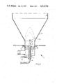
- FIG. 2 is a detail view of the burner in one embodiment of the invention.
- FIG. 3 is a view similar to FIG. 2, illustrating another embodiment thereof.
- FIG. 4 is a similar view of still a third embodiment of the invention.
- the apparatus shown in FIG. 1 is intended for the blowing of perlite or vermiculite which subjects the particles contained in a hopper 3 to a sharp temperature rise in accordance with conventional mineral blowing technology.
- the apparatus comprises a fluidized bed shaft 1, a burner 2 and the hopper 3 which serves as a feeder for delivering the particulate mineral matter to the shaft 1.
- the burner 2 can comprise an air inlet 14 receiving air from a supply line 5, a fuel line or nozzle 4 which is coaxially surrounded by the air inlet and is connected to a fuel supply line, such as the gas line 20, and a line 13 having an outlet 21 opening into the frustoconical bottom 22 of the shaft 1 for delivering a particle-carrier mixture to the burner.
- a fuel supply line such as the gas line 20
- a line 13 having an outlet 21 opening into the frustoconical bottom 22 of the shaft 1 for delivering a particle-carrier mixture to the burner.
- an expanded fluid bed of particles is maintained, the particles being constituted of expanded mineral particles from the hopper 3.
- the particles are entrained by the fluidizing gas via a duct 23 from the head 6 of the shaft 1 into a separating chamber 7 in which the particles are permitted to settle and the particle-free gas is collected at 24 and fed through a cooler 10 where it passes in indirect heat exchange with a cooling fluid.
- the gas is then passed through a gas-cleaning apparatus represented at 11, e.g. a filter, electrostatic precipitator or the like, and is discharged into the atmosphere at 25 by a blower 12 which draws the gas through the cleaning unit.
- the cooling circuit comprises a circulating pump 26 and a heat exchanger 27 from which usable heat can be recovered.
- the heat exchanger 27 can be a waste heat boiler or the like supplying the steam for other plant purposes.
- the combustion sustaining air can be preheated by feeding it at 28 to a heat exchanger loop 29 within the separator 7, the preheated air, e.g. at a temperature of 800° C. or above, being fed to the line 5 and to a line 30 delivering this preheated air as the carrier gas to the particle feed 3 so that the particle-carrier gas mixture is formed in line 13.
- the particles from the gas cleaner 11 can be discharged by a gate or metering device 31 to a collector 32.
- the outlet of blower 12 is wholly connected to a stack for venting the cleaned gas.
- the blown perlite or blown vermiculite particles collected in the separator 7 are passed through a cooler 8 and then metered at 33 to a discharge pipe 9.
- the cooler 8 is in a direct heat exchanger through which the coolant is circulated by a pump 34 through another waste heat boiler 35.
- the mineral particles i.e. the particles of perlite or vermiculite
- the flame propagation direction arrow A in FIG. 2 directly within the flame which is formed as fuel gas from an inlet 17 which mixes with combustion air from line 5.
- the burner is provided with a central inlet 13' having the outwardly flared end 21 and connected to the pipe 13 for delivering the particle-carrier gas mixture into the core of the flame and projecting this mixture through the flame so that the particles move in the flame propagation direction.
- the central member 13' is here surrounded by a tube 17 forming an inlet nozzle for the fuel, in this case natural gas, in an auxiliary around the inlet for the particle-carrier gas mixture.
- the nozzle has been represented at 4.
- a further coaxial duct 14 which serves to feed the combustion air into the burner around the gas nozzle, preferably through a multiplicity of ports 40 in a ceramic body 41 from which the flame extends upwardly with an outline, for example, as represented by the dot-dash lines 42.
- a central oil nozzle 104 is provided and is coaxially surrounded by the tube 113 for supplying the particle-carrier gas mixture.
- the latter is here surrounded by the combustion air supply 5, 14 as in the embodiment of FIG. 2.
- FIG. 4 Still another embodiment has been shown in FIG. 4.
- the gas-particle mixture is fed via the duct 213 into a burner while the air supply for combustion is delivered by the pipe 205 and the duct 214.
- the fuel line 204 communicates with an annular array of fuel nozzles 204' which surround the duct 213.
Abstract
Perlite and vermiculite are blown by injecting the particles, entrained in a carrier gas, through a burner at the bottom of a fluidized bed furnace, into the latter with, within and codirectionally with the flame to ensure uniformity of the product.
Description
My present invention relates to an apparatus for producing expanded perlite, vermiculite and other mineral matter by subjecting the same to elevated temperatures.
It is known that certain mineral matter, especially perlite or vermiculite, can be expanded or blown by subjecting the particles thereof to elevated temperatures.
Apparatus for this purpose can comprise a fluidized bed shaft-type furnace, at least one burner for introducing a fuel and combustion sustaining air into the fluidized bed furnace, and means for introducing particles of the mineral matter to be blown into the fluidized bed whereby the interaction between the heat in the fluidized bed and the particles causes the particles, while they are circulating in the fluidized bed, to expand.
Generally, the burner opens into a lower portion of the fluidized bed shaft while the particle-feed device introduces the particles into the fluidized bed at a location well above the burner, e.g. from a feed tube or the like.
The fluidized bed may be of the so-called expanded type whereby the gas stream, emerging from the top of the bed, entrains the expanded perlite or vermiculite particles from the bed or shaft.
Downstream of the shaft, these particles can be separated from the gas stream and collected.
For the most part, the burner also serves to supply to the furnace, the fluidizing air or gas which generates the fluidized bed movement within the shaft and upwardly along the latter to the outlet.
The shaft can have a height of several meters and the particles are generally fed into the shaft in the lower half of the bed.
Initially, these comparatively dense particles engage in a free fall in which they move counter to rising currents of hot gas above the flame. Ultimately they are circulated into the region of the flame and expanded. Prior to expansion and the desired degree of contact with the flame, however, they may be entrained upwardly, turned, fall downwardly, turned, are carried upwardly a number of times. The interaction is thus a function of the aerodynamic characteristics and statistical variations.
Experience has shown that, for a given output or throughput of the mineral matter, considerable energy is wasted, presumably because of ineffective movement of the particles between the time they are introduced and the time they interact with the flame or in the bed. Furthermore, because the interaction depends in large matter on statistical circumstances and aerodynamic factors, the product which is obtained is frequently nonuniform. This may be a result of the repeated subjection of the particles to severe thermal gradients, in part the result of widely varying residence times in the fluidized bed and like differences. The product, therefore, is generally considered to have poor quality since the apparent density of the product and the pore volume or porosity may vary. The problem is especially acute because a sharp temperature rise, which is necessary for expansion of vermiculite or perlite, cannot always be assured for all particles.
In one earlier system (German open application No. 20 42 896) by a corresponding feed of combustion air in the burner, a turbulent flow of the combustion gases can be generated to provide, in the downwardly conical tapering fluidized bed furnace, a condition in which the mineral matter rides along the wall of the furnace until it reaches the conical region where the particles are picked up by the turbulent flow.
The use of a turbulent stream in this fashion is intended to bring about a more uniform treatment of the mineral matter, but here also individual particles may be subjected to sharply different heating patterns and thus give rise to blown products of varying quality.
In this earlier system, the gases and particles move especially in the coincal region as in a cyclone so that the heavier particles are thrown outwardly and thus are subjected to a different treatment from the lighter particles.
Similar problems with the system are described in U.S. Pat. No. 2,435,927 in which, moreover, the combustion gas and particles are introduced together into the cylindrical portion in a parallel flow, only thereafter entering the turbulent flow.
It is the principal object of the present invention to provide an apparatus for the production of blown perlite or blown vermiculite which is more apt to ensure a uniform treatment of all particles in earlier systems and thus can more reliably bring the particles through a substantially predetermined temperature jump in a uniform and reproducible manner.
Another object of this invention is to provide an improved method of operating an apparatus for the blowing of perlite, vermiculite or like mineral matter.
These objects and others which will become apparent hereinafter are attained, in accordance with the present invention, in an apparatus which comprises a fluidized bed shaft formed with a burner at substantially the apex of a frustoconical tapering lower end and provided with a feed tube for supplying the mineral particles, the carrier gas and the fluids for generating the flame at the burner and in a codirectional flow with the flame.
In other words, in accordance with the present invention, means is provided for generating a flame which preferably is directed upwardly along the axis of the furnace while further means is provided for feeding the particle-carrier gas mixture codirectionally with this flame through the burner, the burner ducts therefore including means for feeding the particulates to one of the burner fluids.
According to an important feature of the invention, the feed duct for the particle-carrier gas mixture opens axially into the burner and is surrounded by the means for building the flame thereof.
The latter means can include means for introducing the fuel and the combination air into the burner coaxially with the outlet for the mixture.
When the burner is a gaseous fuel burner, the fuel nozzle is provided as an annular structure surrounding the central tube through which the particle-carrier gas mixture is fed and, additionally, surrounding a further duct through which the combustion-sustaining gas may be introduced. In an alternative and more preferred construction, the outer annular nozzle of the burner feeds the combustion sustaining gas thereto while the intermediate nozzle delivers the fuel gas and the innermost axial nozzle feeds the particles in the carrier gas mixture.
When the fuel is oil, a crown of oil burner nozzles can surround the tube delivering the particle-carrier gas mixture.
Of course, it is also possible to provide an inverse system in which the particle-carrier gas mixture is fed from one or more ducts surrounding the flame-forming means. For example, a central oil-feed nozzle can be provided and can be surrounded by the air duct and then by the duct delivering the particle-carrier gas mixture.
When the duct delivering the particle-carrier gas mixture is the central duct of the assembly, its free end preferably projects beyond the flame-forming means in the burner and is outwardly flared.
Surprisingly, with the system of the invention, all of the particles traverse the flame similarly and even identically so that all are subjected to the same degree of thermal shock and hence to the same temperature jump so that, if one plots the temperature of the particles against time, the characteristic curve shows a temperature increase with steep flanks.
In addition, with the system of this invention, the residence time of the particles is more or less uniform and heavier particles are not subjected to a different treatment from light particles because of the cyclonic effect. The quality of the product is therefore more uniform with less variation.
A highly important advantage is that the overall height of the fluidized bed furnace can be reduced and the apparatus operated with lower energy comsumption especially when the carrier gas is air, preferably preheated air, and wherein the combustion air is also preheated. Both of these fluids are preferably preheated to about 800° C.
The above and other objects, features and advantages of the present invention will become more readily apparent from the following description, reference being made to the accompanying drawing in which:
FIG. 1 is a flow diagram illustrating the invention;
FIG. 2 is a detail view of the burner in one embodiment of the invention;
FIG. 3 is a view similar to FIG. 2, illustrating another embodiment thereof; and
FIG. 4 is a similar view of still a third embodiment of the invention.
The apparatus shown in FIG. 1 is intended for the blowing of perlite or vermiculite which subjects the particles contained in a hopper 3 to a sharp temperature rise in accordance with conventional mineral blowing technology.
Basically the apparatus comprises a fluidized bed shaft 1, a burner 2 and the hopper 3 which serves as a feeder for delivering the particulate mineral matter to the shaft 1.
According to the invention, as can be seen from FIG. 2, for example, the burner 2 can comprise an air inlet 14 receiving air from a supply line 5, a fuel line or nozzle 4 which is coaxially surrounded by the air inlet and is connected to a fuel supply line, such as the gas line 20, and a line 13 having an outlet 21 opening into the frustoconical bottom 22 of the shaft 1 for delivering a particle-carrier mixture to the burner.
Within the furnace shaft 1, an expanded fluid bed of particles is maintained, the particles being constituted of expanded mineral particles from the hopper 3. The particles are entrained by the fluidizing gas via a duct 23 from the head 6 of the shaft 1 into a separating chamber 7 in which the particles are permitted to settle and the particle-free gas is collected at 24 and fed through a cooler 10 where it passes in indirect heat exchange with a cooling fluid. The gas is then passed through a gas-cleaning apparatus represented at 11, e.g. a filter, electrostatic precipitator or the like, and is discharged into the atmosphere at 25 by a blower 12 which draws the gas through the cleaning unit.
The cooling circuit comprises a circulating pump 26 and a heat exchanger 27 from which usable heat can be recovered. The heat exchanger 27 can be a waste heat boiler or the like supplying the steam for other plant purposes.
The combustion sustaining air can be preheated by feeding it at 28 to a heat exchanger loop 29 within the separator 7, the preheated air, e.g. at a temperature of 800° C. or above, being fed to the line 5 and to a line 30 delivering this preheated air as the carrier gas to the particle feed 3 so that the particle-carrier gas mixture is formed in line 13.
The particles from the gas cleaner 11 can be discharged by a gate or metering device 31 to a collector 32. The outlet of blower 12 is wholly connected to a stack for venting the cleaned gas. The blown perlite or blown vermiculite particles collected in the separator 7 are passed through a cooler 8 and then metered at 33 to a discharge pipe 9.
The cooler 8 is in a direct heat exchanger through which the coolant is circulated by a pump 34 through another waste heat boiler 35.
In the system of the invention, the mineral particles, i.e. the particles of perlite or vermiculite, are fed codirectional with the flame propagation direction (arrow A in FIG. 2) directly within the flame which is formed as fuel gas from an inlet 17 which mixes with combustion air from line 5.
For this purpose the burner is provided with a central inlet 13' having the outwardly flared end 21 and connected to the pipe 13 for delivering the particle-carrier gas mixture into the core of the flame and projecting this mixture through the flame so that the particles move in the flame propagation direction.
The central member 13' is here surrounded by a tube 17 forming an inlet nozzle for the fuel, in this case natural gas, in an auxiliary around the inlet for the particle-carrier gas mixture. The nozzle has been represented at 4.
Surrounding the nozzle is a further coaxial duct 14 which serves to feed the combustion air into the burner around the gas nozzle, preferably through a multiplicity of ports 40 in a ceramic body 41 from which the flame extends upwardly with an outline, for example, as represented by the dot-dash lines 42.
In the embodiment of FIG. 3, which operates with fuel oil, a central oil nozzle 104 is provided and is coaxially surrounded by the tube 113 for supplying the particle-carrier gas mixture. The latter is here surrounded by the combustion air supply 5, 14 as in the embodiment of FIG. 2.
Still another embodiment has been shown in FIG. 4. In this arrangement, the gas-particle mixture is fed via the duct 213 into a burner while the air supply for combustion is delivered by the pipe 205 and the duct 214. In this embodiment, however, the fuel line 204 communicates with an annular array of fuel nozzles 204' which surround the duct 213.
Claims (3)
1. An apparatus for the expansion of particles of a mineral such as perlite and vermiculite, comprising:
means forming an upwardly extending fluidized-bed furnace for expanding said particles;
a burner opening into a lower end of said furnace for generating a flame therein, said furnace being closed at said lower end except for said burner; and
a pipe opening upwardly into said furnace at said lower end for feeding a mixture of said particles and a carrier gas into said flame whereby said particles pass generally in the direction of propagation of said flame through said flame into said furnace, said burner opening axially from below into said furnace and consisting of an annular fuel inlet duct coaxially surrounding said pipe and directed upwardly into said furnace, a combustion air duct opening axially upwardly into said furnace and at least one fuel inlet and coaxially surrounding said fuel inlet assembly, means for feeding fuel exclusively to said fuel inlet duct and means for feeding exclusively air to said combustion air duct, and said combustion air duct being formed with a ceramic ring around said fuel inlet duct and provided with a plurality of spaced apart axially extending bores opening into said furnace and parallel to said pipe and said fuel inlet duct, said ring having a planar horizontal upper surface, said pipe projecting upwardly beyond said surface.
2. The apparatus defined in claim 1, further comprising:
means for receiving a mixture of particle and combustion gases from the top of said furnace and for separating same into a waste gas and a solid product;
means for passing said solid product in a heat exchange with a circulating fluid to cool said product;
means for extracting waste heat from said waste gas; and
means for cleaning said waste gas and discharging same.
3. The apparatus defined in claim 2, further comprising means for heating said combustion air and said carrier gas in indirect heat exchange with a mixture of particles and combustion gas.
Applications Claiming Priority (2)
| Application Number | Priority Date | Filing Date | Title |
|---|---|---|---|
| DE3151164A DE3151164C2 (en) | 1981-12-23 | 1981-12-23 | Device for expanding perlite, vermiculite and similar expanded material |
| DE3151164 | 1981-12-23 |
Publications (1)
| Publication Number | Publication Date |
|---|---|
| US4512736A true US4512736A (en) | 1985-04-23 |
Family
ID=6149597
Family Applications (1)
| Application Number | Title | Priority Date | Filing Date |
|---|---|---|---|
| US06/450,758 Expired - Fee Related US4512736A (en) | 1981-12-23 | 1982-12-17 | Apparatus for the expansion of mineral matter, especially perlite and vermiculite |
Country Status (7)
| Country | Link |
|---|---|
| US (1) | US4512736A (en) |
| AT (1) | AT382013B (en) |
| BE (1) | BE895435A (en) |
| DE (1) | DE3151164C2 (en) |
| FR (1) | FR2518727B1 (en) |
| GB (1) | GB2112770B (en) |
| NL (1) | NL8204975A (en) |
Cited By (31)
| Publication number | Priority date | Publication date | Assignee | Title |
|---|---|---|---|---|
| US4786432A (en) * | 1986-05-05 | 1988-11-22 | Go-Jo Industries, Inc. | Integral dry abrasive soap powders |
| US4786369A (en) * | 1986-05-05 | 1988-11-22 | Go-Jo Industries, Inc. | Integral dry abrasive soap powders |
| WO1992006051A1 (en) * | 1990-10-02 | 1992-04-16 | Proizvodstvennoe Obiedinenie 'kovdorsljuda' | Method and device for swelling granular material |
| DE29716907U1 (en) * | 1997-09-20 | 1998-01-02 | Elbe Werk Roslau Gmbh | Plant technology for the production of granulate from layered silicate |
| DE19854390C2 (en) * | 1998-11-25 | 2001-10-31 | Messer Griesheim Gmbh | Device and method for pearlite production |
| EP1160007A2 (en) * | 2000-05-31 | 2001-12-05 | Messer Griesheim Gmbh | Apparatus and process for expanding vermiculite |
| DE10029724A1 (en) * | 2000-05-31 | 2001-12-13 | Messer Griesheim Gmbh | Device and method for expanding vermiculite |
| US20040079260A1 (en) * | 2002-08-23 | 2004-04-29 | Amlan Datta | Synthetic microspheres and methods of making same |
| WO2004101461A1 (en) * | 2003-05-19 | 2004-11-25 | Francois Jacques Labuschagne | Process for material treatment |
| KR100541411B1 (en) * | 2004-02-11 | 2006-01-11 | 주식회사 재원 | expansion apparatus of expansive stone |
| US20060240967A1 (en) * | 2005-02-24 | 2006-10-26 | Hamid Hojaji | Alkali resistant glass compositions |
| US20070275335A1 (en) * | 2006-05-25 | 2007-11-29 | Giang Biscan | Furnace for heating particles |
| US20080096018A1 (en) * | 2005-12-08 | 2008-04-24 | James Hardie International Finance B.V. | Engineered low-density heterogeneous microparticles and methods and formulations for producing the microparticles |
| US20090146108A1 (en) * | 2003-08-25 | 2009-06-11 | Amlan Datta | Methods and Formulations for Producing Low Density Products |
| US20090156385A1 (en) * | 2003-10-29 | 2009-06-18 | Giang Biscan | Manufacture and use of engineered carbide and nitride composites |
| KR100932725B1 (en) | 2008-02-26 | 2009-12-21 | 김시현 | Manufacturing method of pop stone of calcined mineral |
| US7658794B2 (en) | 2000-03-14 | 2010-02-09 | James Hardie Technology Limited | Fiber cement building materials with low density additives |
| EP2261188A1 (en) * | 2008-03-31 | 2010-12-15 | Bárbara Roman Alemañ | Gypsum mortar with added expanded vermiculite and method for obtaining same |
| US20110021663A1 (en) * | 2009-07-23 | 2011-01-27 | Sacks Abraham J | Light weight aggregate composition |
| US7993570B2 (en) | 2002-10-07 | 2011-08-09 | James Hardie Technology Limited | Durable medium-density fibre cement composite |
| US7998571B2 (en) | 2004-07-09 | 2011-08-16 | James Hardie Technology Limited | Composite cement article incorporating a powder coating and methods of making same |
| US20140215842A1 (en) * | 2012-12-14 | 2014-08-07 | Flash Rockwell Technologies, Llc | Non-Thermal Drying Systems with Vacuum Throttle Flash Generators and Processing Vessels |
| CN104402281A (en) * | 2014-11-21 | 2015-03-11 | 信阳凯米特环保工程有限公司 | Opening expanded perlite complete production equipment |
| US8993462B2 (en) | 2006-04-12 | 2015-03-31 | James Hardie Technology Limited | Surface sealed reinforced building element |
| US9708816B2 (en) | 2014-05-30 | 2017-07-18 | Sacks Industrial Corporation | Stucco lath and method of manufacture |
| US9752323B2 (en) | 2015-07-29 | 2017-09-05 | Sacks Industrial Corporation | Light-weight metal stud and method of manufacture |
| US9797142B1 (en) | 2016-09-09 | 2017-10-24 | Sacks Industrial Corporation | Lath device, assembly and method |
| AT521346B1 (en) * | 2018-05-02 | 2020-01-15 | Dipl Ing Johannes Pohl | Device for producing expanded mineral granules |
| US10760266B2 (en) | 2017-08-14 | 2020-09-01 | Clarkwestern Dietrich Building Systems Llc | Varied length metal studs |
| US11351593B2 (en) | 2018-09-14 | 2022-06-07 | Structa Wire Ulc | Expanded metal formed using rotary blades and rotary blades to form such |
| US20230296323A1 (en) * | 2021-05-11 | 2023-09-21 | Binder + Co Ag | Device for producing expanded granulated material |
Families Citing this family (3)
| Publication number | Priority date | Publication date | Assignee | Title |
|---|---|---|---|---|
| DE102007025099A1 (en) | 2007-05-24 | 2008-11-27 | Ena Elektrotechnologien Und Anlagenbau Gmbh | Blowing mineral granulates e.g. granulated silicates and magnetite by thermal treatment, comprises moving the mineral granulates due to the effect of gravity force by radiation channel and then simultaneously exposing to heat radiation |
| AT511618B1 (en) | 2011-07-13 | 2013-12-15 | Horst Wustinger | BUCKET FOR THE HEAT-RESISTANT PURIFICATION OF PARTICLES OF A BULK |
| CN112125555B (en) * | 2020-09-29 | 2021-12-24 | 江苏奥纳麦格科技有限公司 | Hearth end face sealing structure for perlite expansion furnace |
Citations (10)
| Publication number | Priority date | Publication date | Assignee | Title |
|---|---|---|---|---|
| US2421902A (en) * | 1943-08-31 | 1947-06-10 | Neuschotz Robert | Means of expanding pearlite and like substances |
| US2435927A (en) * | 1943-08-07 | 1948-02-10 | Manning | Drying and disintegrating of gasborne material |
| US2521179A (en) * | 1947-04-11 | 1950-09-05 | G W Abernathy | Apparatus for spraying plastic material |
| US2621034A (en) * | 1947-07-01 | 1952-12-09 | Great Lakes Carbon Corp | Apparatus for expanding minerals |
| US2676892A (en) * | 1953-11-13 | 1954-04-27 | Kanium Corp | Method for making unicellular spherulized clay particles and articles and composition thereof |
| US2838881A (en) * | 1953-07-18 | 1958-06-17 | Union Des Verreries Mecaniques | Apparatus for the manufacture of glass beads |
| US3118658A (en) * | 1960-05-25 | 1964-01-21 | Veit Dennert K G | Apparatus for manufacturing a porous material such as blown clay, by heating |
| DE2042896A1 (en) * | 1970-01-29 | 1972-01-27 | Dennert, Heinz, 8602 Bischberg, Dennert, Hans Veit, 8602 Schlusselfeld | Method and device for expanding clay granules in the circulation flow |
| US4176010A (en) * | 1976-07-28 | 1979-11-27 | Wintershall Aktiengesellschaft | Method of producing petroleum coke calcinate |
| US4347155A (en) * | 1976-12-27 | 1982-08-31 | Manville Service Corporation | Energy efficient perlite expansion process |
Family Cites Families (9)
| Publication number | Priority date | Publication date | Assignee | Title |
|---|---|---|---|---|
| US2431884A (en) * | 1943-08-31 | 1947-12-02 | Neuschotz Robert | Method of expanding pearlite |
| US2746735A (en) * | 1951-10-04 | 1956-05-22 | Combined Metals Reduction Comp | Material mixing burner for processing furnaces |
| FR1140103A (en) * | 1955-09-07 | 1957-07-11 | C V Isoleermaterialen Ind Pull | Method and apparatus for the treatment of perlite by heat |
| NL232500A (en) * | 1957-10-22 | |||
| FR1455482A (en) * | 1965-10-19 | 1966-04-01 | Inst Techniki Budowlanej | Manufacturing process of light aggregates and other construction materials by agglomeration and installation allowing its implementation |
| SU474665A1 (en) * | 1973-06-13 | 1975-06-25 | Государственный Всесоюзный Научно-Исследовательский Институт Строительных Материалов И Конструкций | Shaft furnace fluidized bed |
| CA1107064A (en) * | 1978-04-17 | 1981-08-18 | Charles E. Young | Burner for flash smelting furnace |
| US4290749A (en) * | 1978-10-23 | 1981-09-22 | Johns-Manville Corporation | Perlite expansion process and apparatus therefor |
| DD151995A1 (en) * | 1980-06-19 | 1981-11-11 | Jochen Ludwig | METHOD AND DEVICE FOR THE THERMAL TREATMENT OF SOLIDS |
-
1981
- 1981-12-23 DE DE3151164A patent/DE3151164C2/en not_active Expired
-
1982
- 1982-12-14 AT AT0454382A patent/AT382013B/en not_active IP Right Cessation
- 1982-12-16 FR FR8221117A patent/FR2518727B1/en not_active Expired
- 1982-12-16 GB GB08235848A patent/GB2112770B/en not_active Expired
- 1982-12-17 US US06/450,758 patent/US4512736A/en not_active Expired - Fee Related
- 1982-12-22 BE BE2/59971A patent/BE895435A/en not_active IP Right Cessation
- 1982-12-23 NL NL8204975A patent/NL8204975A/en not_active Application Discontinuation
Patent Citations (10)
| Publication number | Priority date | Publication date | Assignee | Title |
|---|---|---|---|---|
| US2435927A (en) * | 1943-08-07 | 1948-02-10 | Manning | Drying and disintegrating of gasborne material |
| US2421902A (en) * | 1943-08-31 | 1947-06-10 | Neuschotz Robert | Means of expanding pearlite and like substances |
| US2521179A (en) * | 1947-04-11 | 1950-09-05 | G W Abernathy | Apparatus for spraying plastic material |
| US2621034A (en) * | 1947-07-01 | 1952-12-09 | Great Lakes Carbon Corp | Apparatus for expanding minerals |
| US2838881A (en) * | 1953-07-18 | 1958-06-17 | Union Des Verreries Mecaniques | Apparatus for the manufacture of glass beads |
| US2676892A (en) * | 1953-11-13 | 1954-04-27 | Kanium Corp | Method for making unicellular spherulized clay particles and articles and composition thereof |
| US3118658A (en) * | 1960-05-25 | 1964-01-21 | Veit Dennert K G | Apparatus for manufacturing a porous material such as blown clay, by heating |
| DE2042896A1 (en) * | 1970-01-29 | 1972-01-27 | Dennert, Heinz, 8602 Bischberg, Dennert, Hans Veit, 8602 Schlusselfeld | Method and device for expanding clay granules in the circulation flow |
| US4176010A (en) * | 1976-07-28 | 1979-11-27 | Wintershall Aktiengesellschaft | Method of producing petroleum coke calcinate |
| US4347155A (en) * | 1976-12-27 | 1982-08-31 | Manville Service Corporation | Energy efficient perlite expansion process |
Cited By (51)
| Publication number | Priority date | Publication date | Assignee | Title |
|---|---|---|---|---|
| US4786432A (en) * | 1986-05-05 | 1988-11-22 | Go-Jo Industries, Inc. | Integral dry abrasive soap powders |
| US4786369A (en) * | 1986-05-05 | 1988-11-22 | Go-Jo Industries, Inc. | Integral dry abrasive soap powders |
| WO1992006051A1 (en) * | 1990-10-02 | 1992-04-16 | Proizvodstvennoe Obiedinenie 'kovdorsljuda' | Method and device for swelling granular material |
| DE29716907U1 (en) * | 1997-09-20 | 1998-01-02 | Elbe Werk Roslau Gmbh | Plant technology for the production of granulate from layered silicate |
| DE19854390C2 (en) * | 1998-11-25 | 2001-10-31 | Messer Griesheim Gmbh | Device and method for pearlite production |
| US7658794B2 (en) | 2000-03-14 | 2010-02-09 | James Hardie Technology Limited | Fiber cement building materials with low density additives |
| US8603239B2 (en) | 2000-03-14 | 2013-12-10 | James Hardie Technology Limited | Fiber cement building materials with low density additives |
| US7727329B2 (en) | 2000-03-14 | 2010-06-01 | James Hardie Technology Limited | Fiber cement building materials with low density additives |
| US8182606B2 (en) | 2000-03-14 | 2012-05-22 | James Hardie Technology Limited | Fiber cement building materials with low density additives |
| DE10029724A1 (en) * | 2000-05-31 | 2001-12-13 | Messer Griesheim Gmbh | Device and method for expanding vermiculite |
| DE10029724C2 (en) * | 2000-05-31 | 2003-07-31 | Messer Griesheim Gmbh | Vermiculite blowing procedure |
| EP1160007A3 (en) * | 2000-05-31 | 2004-01-07 | Messer Griesheim GmbH | Apparatus and process for expanding vermiculite |
| EP1160007A2 (en) * | 2000-05-31 | 2001-12-05 | Messer Griesheim Gmbh | Apparatus and process for expanding vermiculite |
| US20040081827A1 (en) * | 2002-08-23 | 2004-04-29 | Amlan Datta | Synthetic microspheres and methods of making same |
| US20040080063A1 (en) * | 2002-08-23 | 2004-04-29 | Amlan Datta | Synthetic microspheres and methods of making same |
| US7878026B2 (en) | 2002-08-23 | 2011-02-01 | James Hardie Technology Limited | Synthetic microspheres and methods of making same |
| US7651563B2 (en) | 2002-08-23 | 2010-01-26 | James Hardie Technology Limited | Synthetic microspheres and methods of making same |
| US7666505B2 (en) | 2002-08-23 | 2010-02-23 | James Hardie Technology Limited | Synthetic microspheres comprising aluminosilicate and methods of making same |
| US20040079260A1 (en) * | 2002-08-23 | 2004-04-29 | Amlan Datta | Synthetic microspheres and methods of making same |
| US7993570B2 (en) | 2002-10-07 | 2011-08-09 | James Hardie Technology Limited | Durable medium-density fibre cement composite |
| WO2004101461A1 (en) * | 2003-05-19 | 2004-11-25 | Francois Jacques Labuschagne | Process for material treatment |
| US20070059199A1 (en) * | 2003-05-19 | 2007-03-15 | Labuschagne Francois J | Process for material treatment |
| US20090146108A1 (en) * | 2003-08-25 | 2009-06-11 | Amlan Datta | Methods and Formulations for Producing Low Density Products |
| US20090200512A1 (en) * | 2003-10-29 | 2009-08-13 | Giang Biscan | Manufacture and Use of Engineered Carbide and Nitride Composites |
| US20090156385A1 (en) * | 2003-10-29 | 2009-06-18 | Giang Biscan | Manufacture and use of engineered carbide and nitride composites |
| US7897534B2 (en) | 2003-10-29 | 2011-03-01 | James Hardie Technology Limited | Manufacture and use of engineered carbide and nitride composites |
| KR100541411B1 (en) * | 2004-02-11 | 2006-01-11 | 주식회사 재원 | expansion apparatus of expansive stone |
| US7998571B2 (en) | 2004-07-09 | 2011-08-16 | James Hardie Technology Limited | Composite cement article incorporating a powder coating and methods of making same |
| US20060240967A1 (en) * | 2005-02-24 | 2006-10-26 | Hamid Hojaji | Alkali resistant glass compositions |
| US7744689B2 (en) | 2005-02-24 | 2010-06-29 | James Hardie Technology Limited | Alkali resistant glass compositions |
| US20080096018A1 (en) * | 2005-12-08 | 2008-04-24 | James Hardie International Finance B.V. | Engineered low-density heterogeneous microparticles and methods and formulations for producing the microparticles |
| US8609244B2 (en) | 2005-12-08 | 2013-12-17 | James Hardie Technology Limited | Engineered low-density heterogeneous microparticles and methods and formulations for producing the microparticles |
| US8993462B2 (en) | 2006-04-12 | 2015-03-31 | James Hardie Technology Limited | Surface sealed reinforced building element |
| US20070275335A1 (en) * | 2006-05-25 | 2007-11-29 | Giang Biscan | Furnace for heating particles |
| KR100932725B1 (en) | 2008-02-26 | 2009-12-21 | 김시현 | Manufacturing method of pop stone of calcined mineral |
| EP2261188A4 (en) * | 2008-03-31 | 2011-10-05 | Aleman Barbara Roman | Gypsum mortar with added expanded vermiculite and method for obtaining same |
| EP2261188A1 (en) * | 2008-03-31 | 2010-12-15 | Bárbara Roman Alemañ | Gypsum mortar with added expanded vermiculite and method for obtaining same |
| US20110021663A1 (en) * | 2009-07-23 | 2011-01-27 | Sacks Abraham J | Light weight aggregate composition |
| US20140215842A1 (en) * | 2012-12-14 | 2014-08-07 | Flash Rockwell Technologies, Llc | Non-Thermal Drying Systems with Vacuum Throttle Flash Generators and Processing Vessels |
| US9618263B2 (en) * | 2012-12-14 | 2017-04-11 | Flash Rockwell Technologies, Llc | Non-thermal drying systems with vacuum throttle flash generators and processing vessels |
| US9708816B2 (en) | 2014-05-30 | 2017-07-18 | Sacks Industrial Corporation | Stucco lath and method of manufacture |
| CN104402281A (en) * | 2014-11-21 | 2015-03-11 | 信阳凯米特环保工程有限公司 | Opening expanded perlite complete production equipment |
| CN104402281B (en) * | 2014-11-21 | 2016-09-14 | 信阳凯米特环保工程有限公司 | Perforate expanded perlite complete production unit |
| US9752323B2 (en) | 2015-07-29 | 2017-09-05 | Sacks Industrial Corporation | Light-weight metal stud and method of manufacture |
| US9797142B1 (en) | 2016-09-09 | 2017-10-24 | Sacks Industrial Corporation | Lath device, assembly and method |
| US10760266B2 (en) | 2017-08-14 | 2020-09-01 | Clarkwestern Dietrich Building Systems Llc | Varied length metal studs |
| AT521346B1 (en) * | 2018-05-02 | 2020-01-15 | Dipl Ing Johannes Pohl | Device for producing expanded mineral granules |
| AT521346A4 (en) * | 2018-05-02 | 2020-01-15 | Dipl Ing Johannes Pohl | Device for producing expanded mineral granules |
| US11351593B2 (en) | 2018-09-14 | 2022-06-07 | Structa Wire Ulc | Expanded metal formed using rotary blades and rotary blades to form such |
| US20230296323A1 (en) * | 2021-05-11 | 2023-09-21 | Binder + Co Ag | Device for producing expanded granulated material |
| US11859909B2 (en) * | 2021-05-11 | 2024-01-02 | Omya International Ag | Device for producing expanded granulated material |
Also Published As
| Publication number | Publication date |
|---|---|
| FR2518727B1 (en) | 1987-07-10 |
| BE895435A (en) | 1983-04-15 |
| DE3151164C2 (en) | 1985-02-07 |
| GB2112770B (en) | 1985-07-24 |
| GB2112770A (en) | 1983-07-27 |
| FR2518727A1 (en) | 1983-06-24 |
| ATA454382A (en) | 1986-05-15 |
| AT382013B (en) | 1986-12-29 |
| DE3151164A1 (en) | 1983-06-30 |
| NL8204975A (en) | 1983-07-18 |
Similar Documents
| Publication | Publication Date | Title |
|---|---|---|
| US4512736A (en) | Apparatus for the expansion of mineral matter, especially perlite and vermiculite | |
| US4559719A (en) | Method for processing matter in a turbulent mass of particulate material | |
| EP1230515B1 (en) | Method and apparatus for combustion of residual carbon in fly ash | |
| JPH01107090A (en) | Method and device for controlling cyclone dust-collecting efficiency and circulation ratio of fluidized bed reactor | |
| JPS63274642A (en) | Cement manufacturing apparatus | |
| JP2657526B2 (en) | Method for improving solids distribution in a circulating fluidized bed system | |
| CA1130092A (en) | Spray drying apparatus utilizing pulse jet engines | |
| JPH06182188A (en) | Fluid bed reactor device and method of operating said device | |
| US4565139A (en) | Method and apparatus for obtaining energy | |
| US4106892A (en) | Apparatus for heat treatment using downwardly swirling hot gas flow | |
| EA012789B1 (en) | Plant for the conveyance of fine-grained solids | |
| JPH02243545A (en) | Method and device for manufacture of cement clinker from raw material metal | |
| AU2003294753B2 (en) | Method and plant for producing low-temperature coke | |
| US3119379A (en) | Apparatus for combustion of fuels | |
| EP0393931A2 (en) | Ash treatment system and process | |
| US3172744A (en) | Removal of solids from a solid laden gas | |
| US4419964A (en) | Combustion plant | |
| JPS63123434A (en) | Ash sorter | |
| JPS59127662A (en) | Method and apparatus for treating powder or particles | |
| US3201099A (en) | Methods of expanding perlite and like materials | |
| US3441258A (en) | Method and apparatus for preheating particulate feed material for a rotary kiln | |
| AU552679B2 (en) | Particle entrainment combustion | |
| US4335663A (en) | Thermal processing system | |
| US4298339A (en) | Method of heat treating a material | |
| JPH0236877B2 (en) | RYUDOSHOSHIKINETSUKOKANKIOYOBISONOSADOHOHO |
Legal Events
| Date | Code | Title | Description |
|---|---|---|---|
| AS | Assignment |
Owner name: DEUTSCHE PERLITE GMBH, KIPPERSTR. 19, 4600 DORTMUN Free format text: ASSIGNMENT OF ASSIGNORS INTEREST.;ASSIGNOR:WADER, HERIBERT;REEL/FRAME:004108/0711 Effective date: 19821213 |
|
| REMI | Maintenance fee reminder mailed | ||
| LAPS | Lapse for failure to pay maintenance fees | ||
| STCH | Information on status: patent discontinuation |
Free format text: PATENT EXPIRED DUE TO NONPAYMENT OF MAINTENANCE FEES UNDER 37 CFR 1.362 |
|
| FP | Lapsed due to failure to pay maintenance fee |
Effective date: 19890423 |